Advanced Sheet Metal Design Using NX Cad Challenge_5_Odd Shaped Enclosure
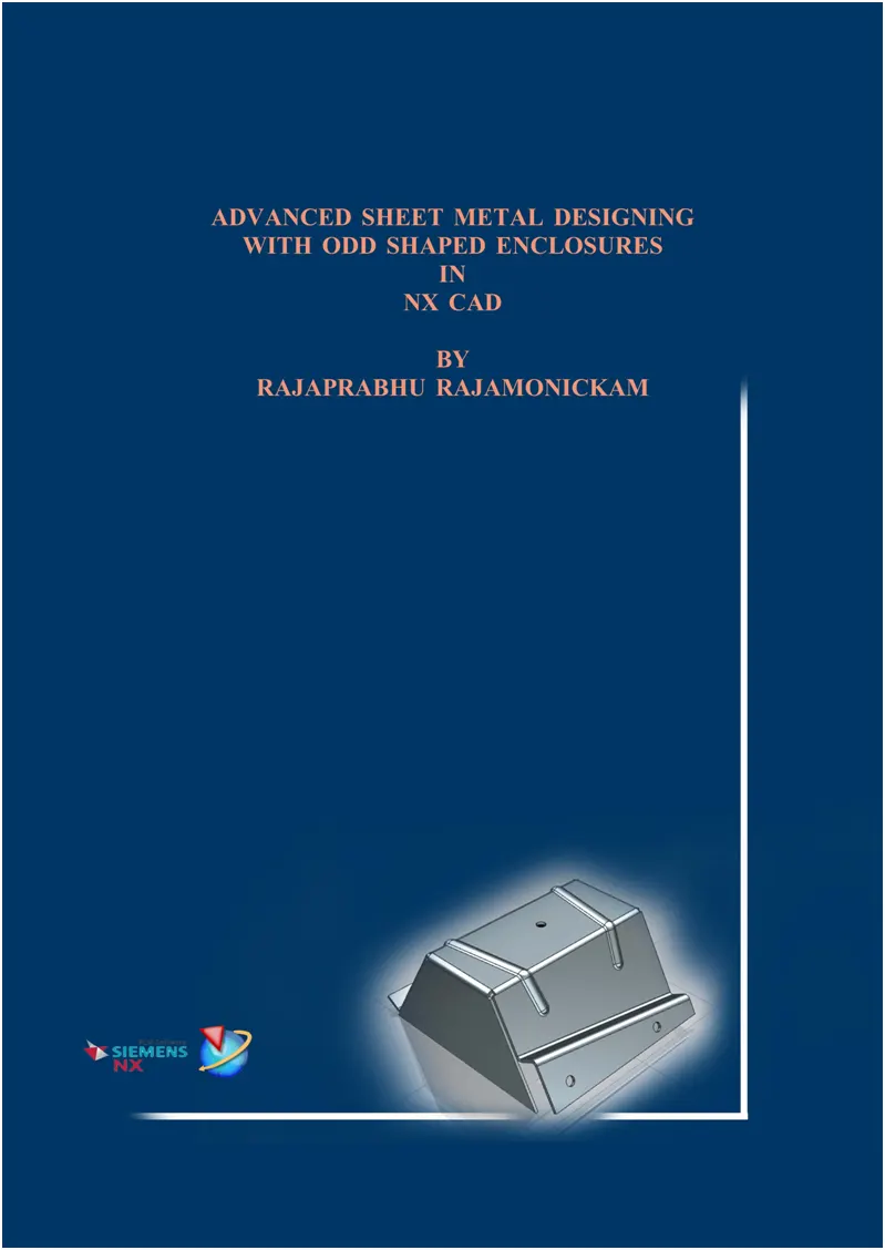
Advanced Sheet Metal Designing with Odd Shaped Enclosures in NX CAD
Objective:
To design a model of sheet metal with odd shaped enclosures using the sheet metal design tools application in Siemens NX CAD Software.
Introduction:
Sheet metal forming can be used in different industrial areas. Various computer-controlled manufacturing processes are used. These manufacturing processes are optimally adapted to the different materials, material thicknesses and other important factors.
Sheet Metal is metal formed by an industrial process into thin, flat pieces. Sheet metal is one of the fundamental forms used in metalworking, and it can be cut and bent into a variety of shapes. Countless everyday objects are fabricated from sheet metal. Thicknesses can vary significantly; extremely thin sheets are considered foil or leaf, and pieces thicker than 6mm (0.25in) are considered plate steel or “structural steel”
Sheet metal is used in automobile and truck (lorry) bodies, airplane fuselages and wings, medical tables, roofs for buildings (architecture), and many other applications.
Sheet metal forming is suitable for almost all manufacturing industries: The automotive industry uses it to produce heavy-duty body parts such as fenders, hoods and vehicle doors. The food industry uses cans that are made with the help of forming technology. It can also be used to manufacture components such as wings and propellers for the aerospace industry. Suppliers of household appliances also benefit from the various sheet metal forming processes. They use the finished sheet metal parts in their kitchen hoods, sinks and freezers. In addition, sheet metal forming is used in apparatus construction, plant construction, electrical, pharmaceutical, medical, measurement and control technology, among others. Ventilation, air conditioning and communications technology also use these methods.
There are many different metals that can be made into sheet metal, such as aluminium, brass, copper, steel, tin, nickel and titanium. For decorative uses, some important sheet metals include silver, gold, and platinum (platinum sheet metal is also utilized as a catalyst).
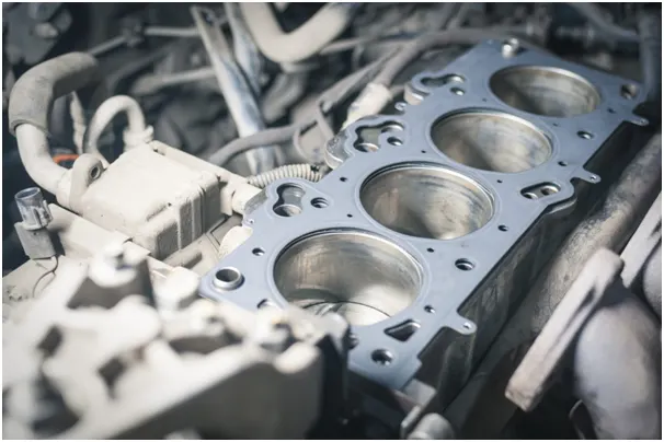
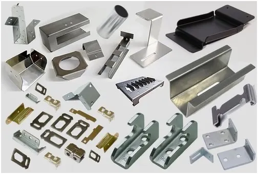
Creating fast, accurate flat patterns is the goal of any organization that manufactures products which contain sheet metal parts. NX Sheet metal provides a set of tools within the NX design environment that allows for simple and fast design of sheet metal parts, dependent on their material and manufacturing process, the most common of which is straight brake sheet metal forming.
As the name suggests, straight brake sheet metal forming uses manufacturing tooling (press brakes) that form the part by bending the metal blanks along linear or straight lines. This is an efficient and cost-effective way to create simple brackets, housings, and enclosures across many industries.
A brake is a metal working machine that allows the bending of sheet metal. A cornice brake only allows for simple bends and creases, while box and pan brake also allow one to form box and pan shapes. It is also known as a bending machine or bending brake or in Britain as a sheet metal folder or just a folder.
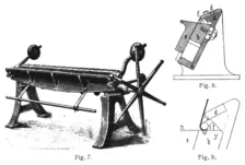
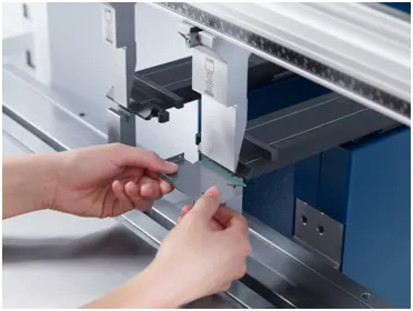
(Fig.) Manually driven bending brake
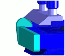
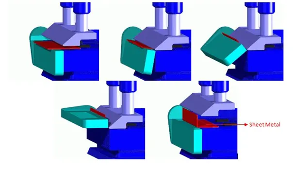
(Fig.) Cornice brake
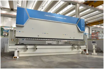
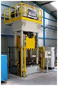
(Fig.) Hydraulic press
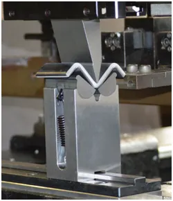
(Fig.) Sheet metal bending in press brake
Brakes come in sizes suitable for light aluminium or brass for small boxes and operated by hand, up to industrial sixed and counterweighted hand-operated or hydraulic machines suitable for large sheets of steel.
With Siemens Nx Sheet metal, formed and unformed representations of the parts are created closely following the industry workflows and best practices for bending calculations, tooling, and sheet metal features. The value lies in improving quality and reducing cost of sheet metal parts by producing an accurate sheet metal pattern as the correct input for part manufacture, whether internally or to a supplier.
In this project we are going to design a model of sheet metal with odd shaped enclosures in Siemens Nx CAD software.
Design Methodology:
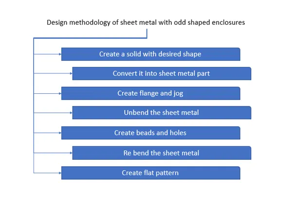
(fig.)Design methodology of sheet metal with odd shaped enclosures
Tools and Features used while Designing:
Sheet Metal application tools are mainly used in designing the model of sheet metal with odd shaped enclosures.
Let’s have a look at the tools and features used in designing the sheet metal model with odd shaped enclosures.
The following features are found under home tab in sheetmetal application workbench in NX CAD.
Extrude:
This feature creates a feature by extruding a section along a vector.
Sheetmetal from solid:
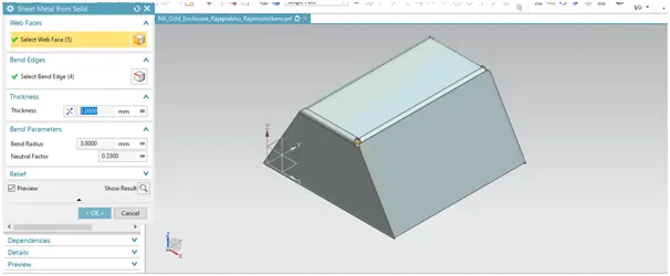
This feature builds a sheet metal model that takes its shape from a collection of planar faces.
Flange:
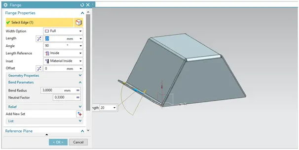
This feature adds a flat flange at an angle to a planar face and adds a bend between the two.
Jog:
This feature modifies the model by lifting material on one side of a sketch line, adding a flange between the two sides.
Unbend:
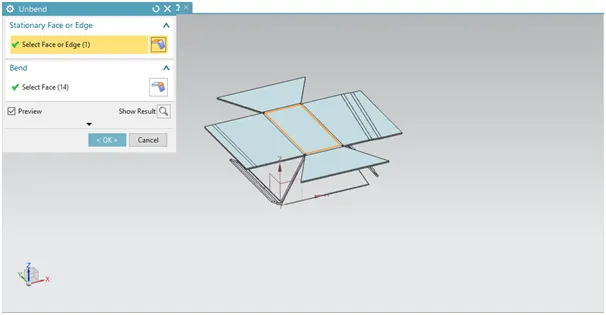
This feature flattens a bend and the material adjacent to the bend.
Bead:
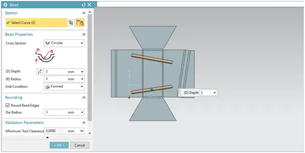
This feature lifts material along the contour of a sketch that simulates a stamping tool.
Hole:
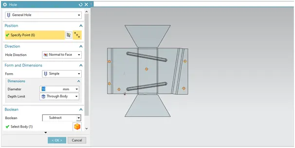
This feature adds a hole to one or more solid bodies in a part or assembly with options for counterbored, countersunk, and threaded.
Rebend:
This feature restores an unbend feature to its previous bend state, along with any features added after the unbend feature.
Flat Pattern:
This feature creates a flat pattern feature from the formed sheet metal part.
Steps involved:
- First a sketch is made in Datum Coordinate plane and dimensioned as required.
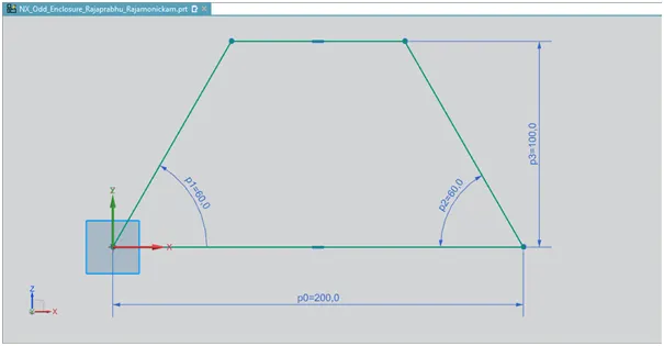
- Then the sketch extruded with extrude feature to form a solid.
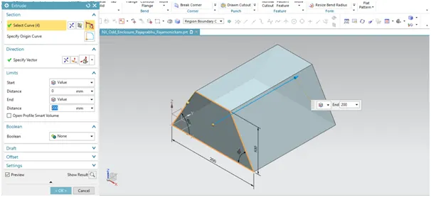
- Used sheet metal from solid feature to create a sheet metal from the extruded model.
- Created flange on one side and jog on other side using flange and jog features.
- A cross line sketch is created for jog feature.
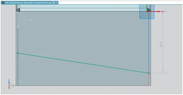
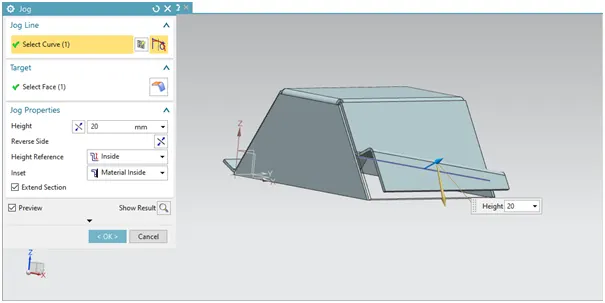
- After creating the jog, unbend the sheet metal with unbend feature to add extra shapes like beads and holes.
- Two beads are created with line sketch using bead feature.
- Holes of general type are created with sketch points as reference.
- Then the rebend feature is used to rebend the model.
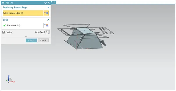
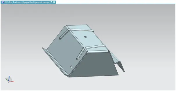
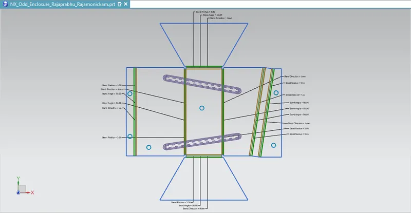
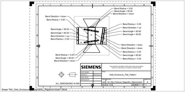
- And finally, flat pattern feature is used to transform the model into flat 2d sketch pattern and then transferred into drawing sheet.
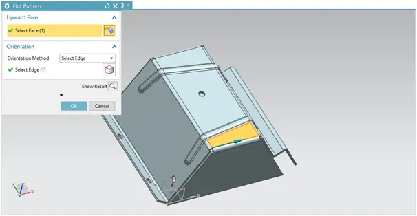
Flat pattern view can be changed model views from part navigator and also by replace view option.
Final model:
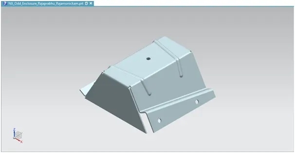
With Drafting application in NX CAD software the model is derived into a drawing sheet.
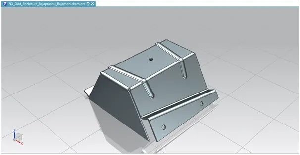
Sheet metal model in Trueshading visualization:
Standard Views of Sheet metal model:
Front View:

Side View:
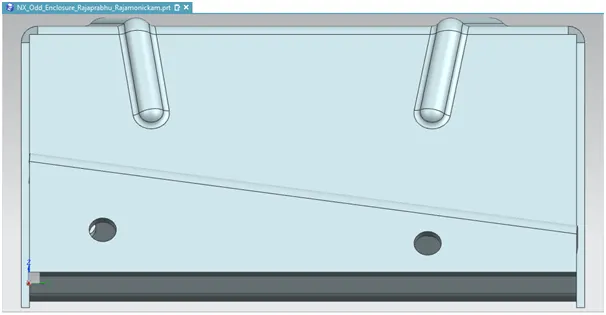
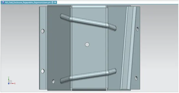
Top View:
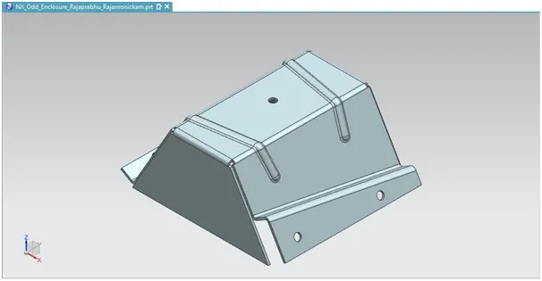
Isometric View:
Conclusion:
A model of sheet metal with odd shaped enclosures is successfully designed in Siemens NX Cad Software using Sheet metal application tools.