Quasi-static Roof Crush simulation for Dodge Neon BIW model with an impactor of FMVSS 216 Standards
AIM :
- To perform Quasi-static Roof Crush simulation for the given Dodge Neon BIW model with an impactor of FMVSS 216 Standards
- To plot the force vs. displacement curve and to check that the FMVSS 216 target load of ( 3 * GVW) has been met.
PROCEDURE :
- Importing BIW model in Hypermesh (RADIOSS Profile)
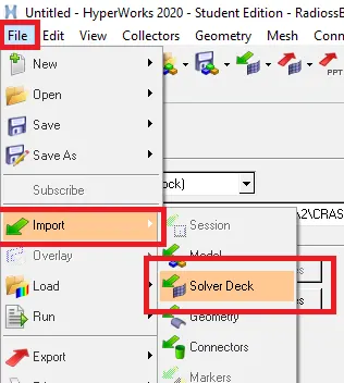
To import the given model we will select import solver deck in the import tab, then we will select the file we wish to import in this case we select neon_roof_0000.rad file under RADIOSS block.after importing we can see the model appears in wireframe mode which we can turn it into shaded mode.
first step in the solver deck setup of this model is to check the units in which the Geometry has been modelled
- Check unit system and either follow[Mg mm s] or [Kg mm ms].
we can assign all the boundary conditions,sections,masses to the model in hypermesh/hypercrash.here we imported the model we got and found out that the unit system assigned to the model is in kg,mm,ms by checking the BEGIN_CARD under cards in the Model tab as shown.
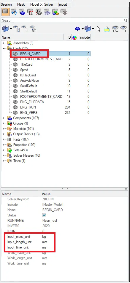
so we will keep it without making any changes to it and follow the same units through the simulation process.to cross-check we can open the input rad file in notepad to see the units system.

- Positioning of the impactor
we make use of Translate & Rotate option in hypermesh tools to manually position the impactor component on to the side top of the car.
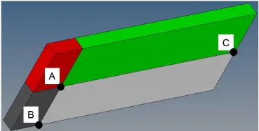
Here are some directions/steps which is given in challenge that we need to follow in the order to position the Impactor at the right location:
1. A 180° rotation about the global z-axis with the point opposite to C as base point
2. A -5° rotation about the axis through axis AB
3. A 25° rotation about the axis through axis AC
4. A translation to put point A at global ( -3500.00, 584.822, 1343.06)
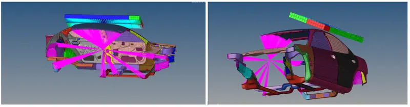
After completing this steps the impactor is placed with some gap above the top edge of the vehicle roof.
Impactor before positioning-
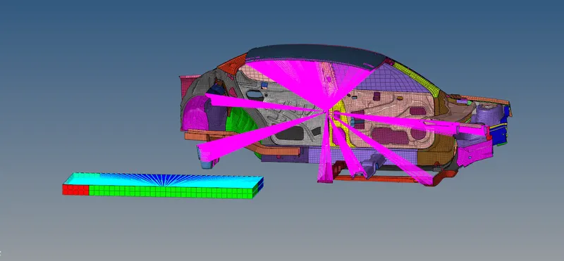
Impactor after positioning -
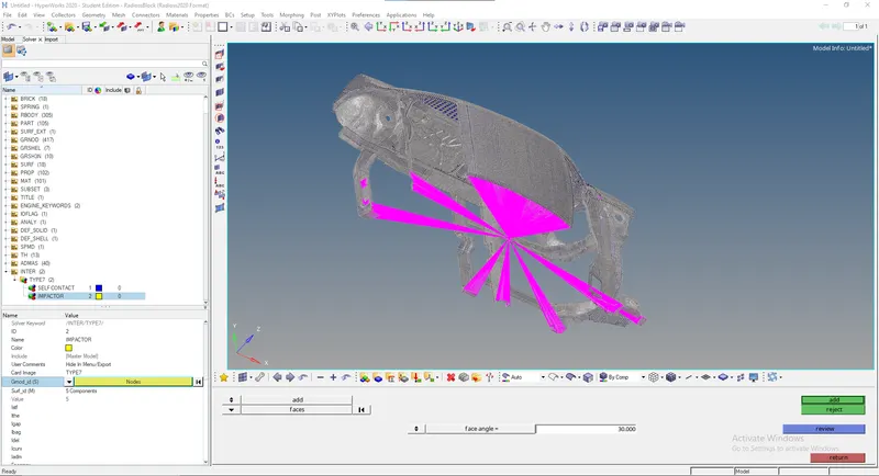
- creating the Type7 contact interface between the impactor and the car
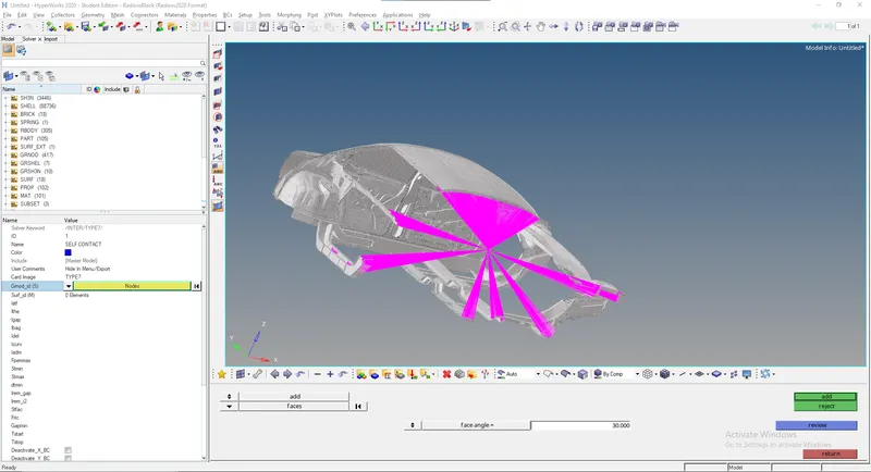
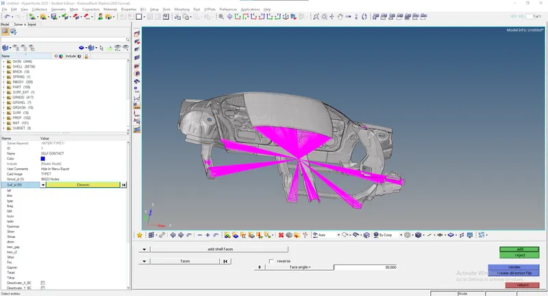
In this case two interfaces has to be created. The first one is all the components in the car should be selected as master and slave. The second one is the components of impactor should be given as master and components of car must be given as slave
Go to Model>>Groups>>Create a new interface with TYPE 7 contact interface with recommended parameters
Interface TYPE7 is a multi-usage impact interface, modeling contact between a master surface and a group of slave nodes. It is also possible to consider heat transfer and heat friction.
- A node can at the same time be a slave and a master node.
- Each slave node can impact each master segment; except if it is connected to this segment.
- A node can impact on more than one segment.
- A node can impact on the two sides, on the edges and on the corners of each segments.
- It is a fast search algorithm without limitations.
- Time step is reduced in case of high impact speed or contacts with small gap.
- It does not work properly if used with a rigid body at high impact speed or rigid body with small gap.
- It does not solve edge to edge contact.
Parameters which control type 7 card
- Igap - determines how the size of the gap is calculated
-
Gapmin Minimum gap for impact activation - Inacti - Action to be taken if initial penetration exist
- Istif - affect how stiffness of the interface is calculated
- Iform - Friction formulation is of two types( Viscous and stiffness type) . The laer is used normally for structural analysis.
- Istif - The minimum stiffness is controled here
- Idel - If elements are attached to a deleted slave node this option specifies what is to be done to control it
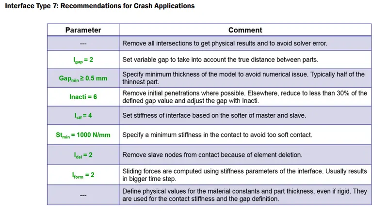
in first group we select the impactor elements as master and car as slaves.
in the second we select car elements and nodes as both master and slaves.
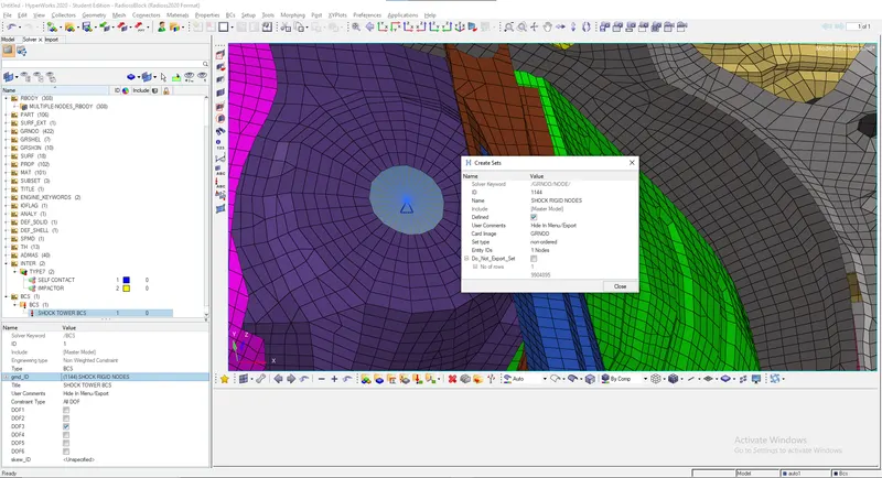
- Creating boundary conditions for the suspension lock:
here we will select the nodes around perimeter of of suspension shock tower and create a rigid body and assign boundary condition to it to restrict it from translation in negative y axis direction since there is no floor or road is present in the model so to avoid the dispacement of the car body towards down we will restrict the DOF in that direction for getting proper result in the simulation.
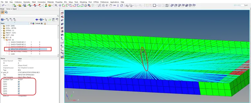
- The impactor assembly contains a spring attached for stability. Create a BCS collector to fix the free end of the spring.
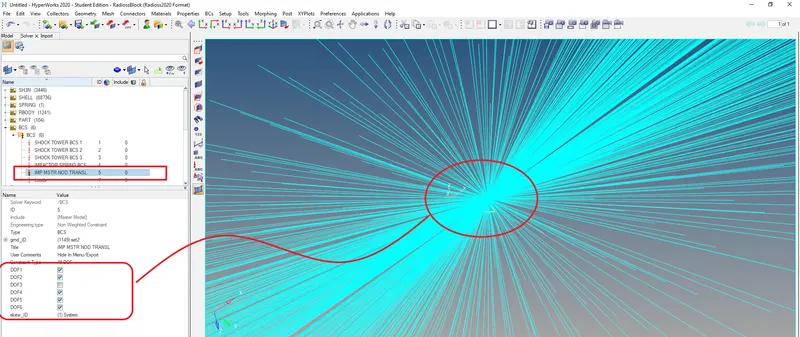
here we go to Solver>Create>Boundary Condition>BCS then we will Select the free end of the spring element for setting up the DOF's which needs to be arrested. Similarly create BCS card for impactor master node and for all the rigid body nodes (arrest all DOF's).
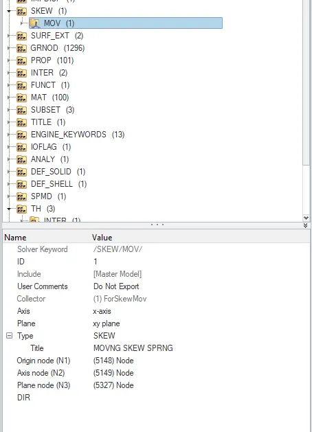
- Create a moving SKEW to define the direction normal to the impactor’s
face.
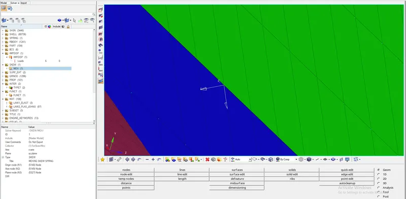
before creating bcs for the spring end of the impactor we have to define the skew in order to assign a direction normal to the impactor face by right click on empty space under solver then create>skew>mov will create a moving skew
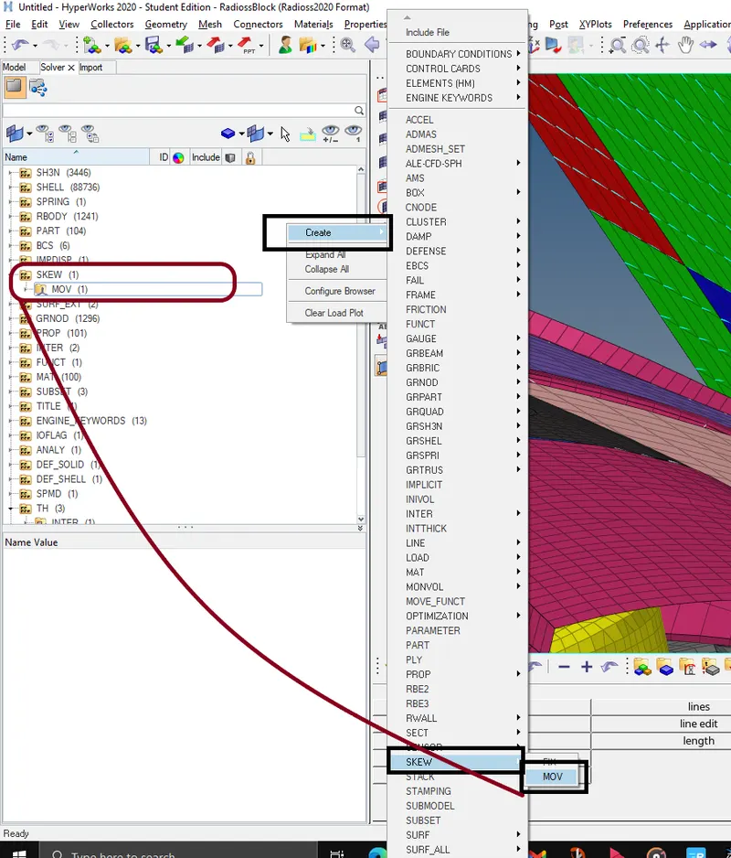
after the skew is created we will assign three nodes to define three axis in that we will make z axis to be facing in normal to the car so that the impactor moves towards the car
- Create a BCS collector to guide the master node of the impactor rigid body
here we will create BCS collector to guide the master node of the impactor rigid body so that it is free to translate normal to the face of the impactor, but is fixed in all other DOFs.
- Imposed Displacement
Impose the velocity of the impactor starting from 0 mm/s at t = 0. The displacement of the impactor should be 200 mm @ 200 ms.
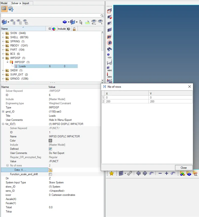
To give an Imposed Displacement, we must put in a curve in the form of a graph as input. To create an Imposed Displacement in the form of a boundary condition, we simply need to create a Boundary condition. So, to do this go to Solver> Right Click>Create>Boundary Conditions>IMPDISP option and Select the Master node of the impactor Rigid Body by creating grnd_ID and Set in Direction Z and Select the Skew ID which is already created in SKEW.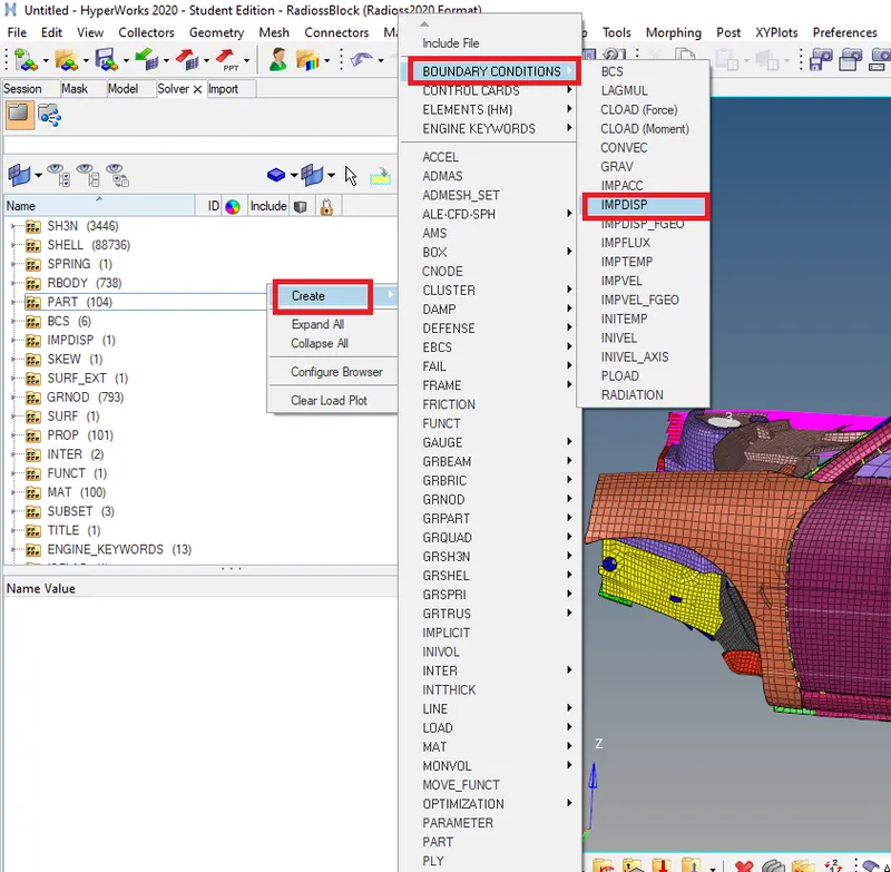
in this case we give the Imposed displacement to the Master node of the Rigid body connecting all the nodes of the impactor. If the Master node is moving towards the direction of the vehicle, it will bring all the nodes which means the entire Impactor with it.
while creating the imposed displacement we will assign curve in the form of a graph as input .To create a curve, go to the Model Browser > right-click on empty space> Create > Curve > New > we will specify the name for the curve then we give inputs X and Y coordinates as (0, 0) and (200,200) .
- TH request :
here we will create a time history output request i.e., we are going to request all required output which we need. To request Solver > Create > TH > select the type we need to record.
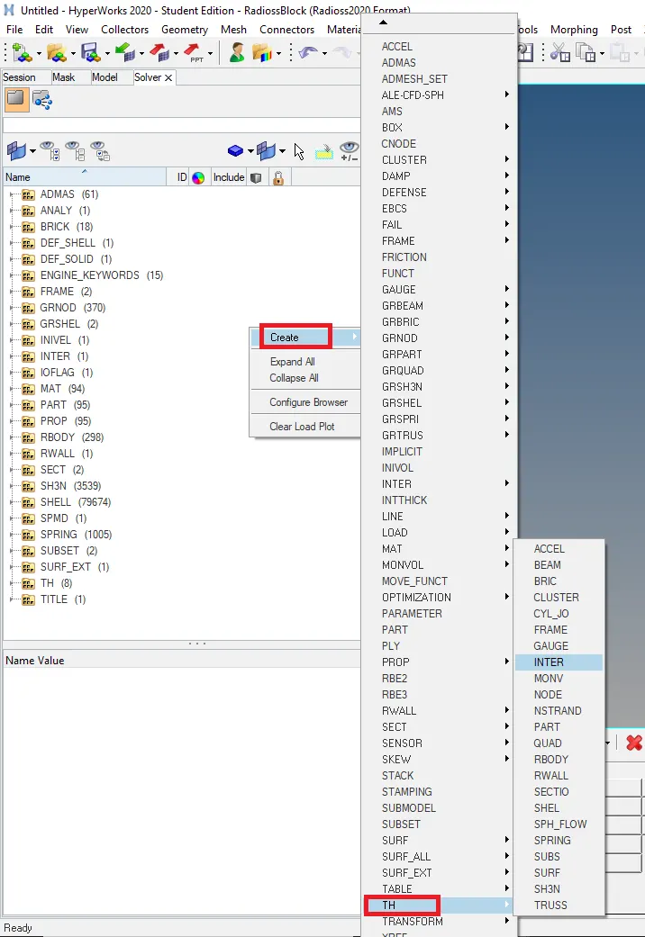
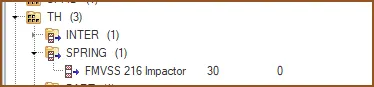
here we have requested TH for spring element in the impactor,car body and impactor nodes for studying the formation of various enrgies and deformations.
- Checking and updating the required cards to set time steps for the simulation :
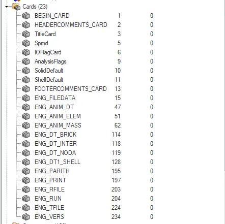
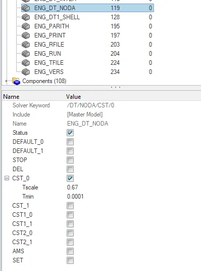
few cards are added manually by importing them from ANALYSIS>CONTROL CARD in hypermesh and adding required values like Tscale and Tmin. some of the control cards we have imported are ENG_DT_BRICK,ENG_DT_INTER,ENG_DT_NODA,ENG_DT1_SHELL etc.,
- Engine File management :
• Use a constant nodal time step
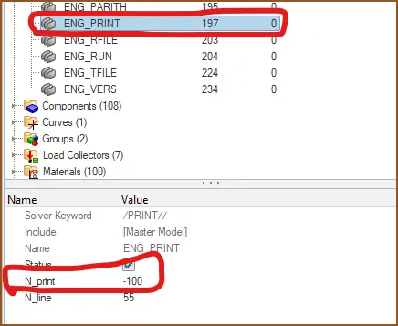
• Print time history every 0.0001 seconds
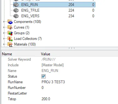
• Solve for 200 ms
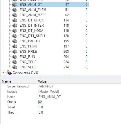
• Create an animation file every 0.005 seconds
- Running model checker to ensure good quality
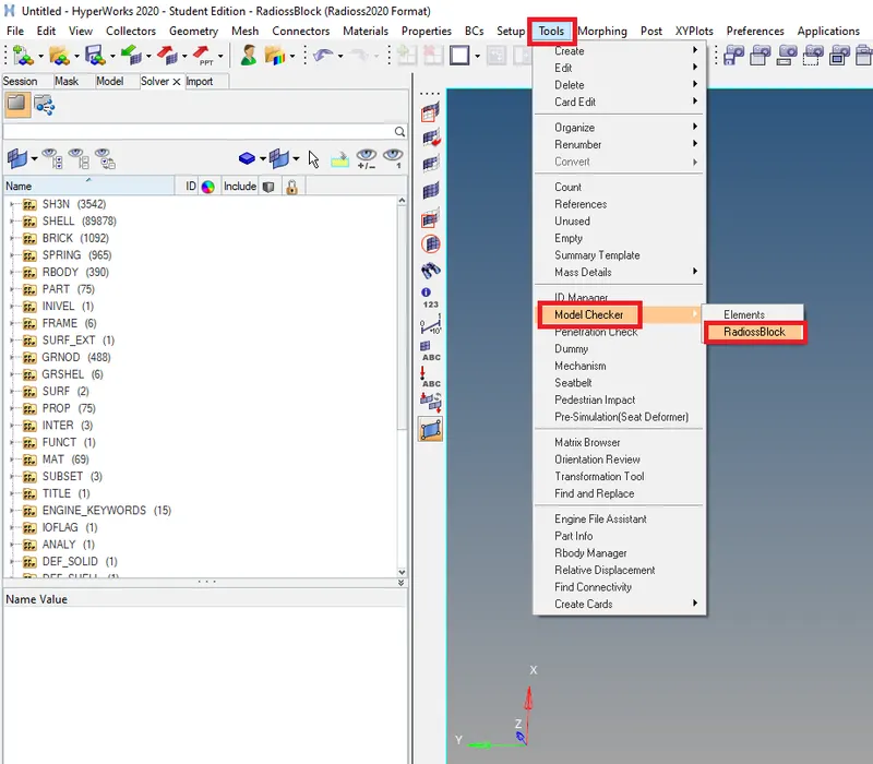
This model checker will show all the warnings and errors in the model. All the errors must be resolved and the warnings if not critical, can be left in the simulation, else, they too must be resolved. Like this the model can be checked and be resolved for any errors in the model.
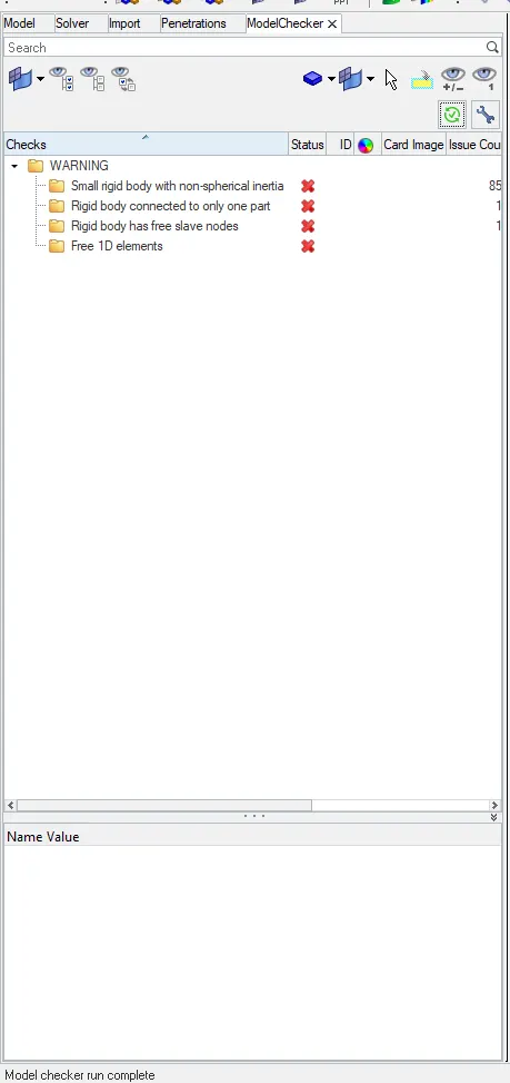
from the image above we can say that the model is free of errors so now we can move forward to run the simulation.
Animation files :
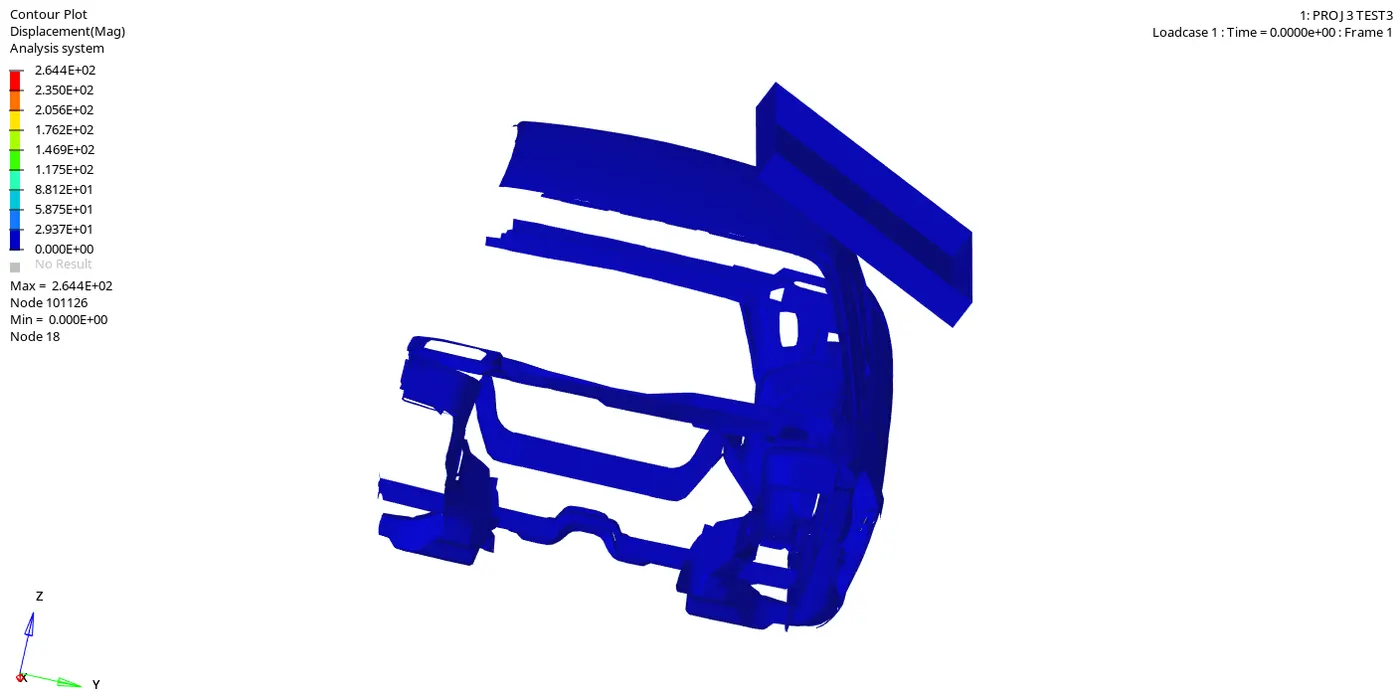
Animation can be seen for different terms like dispacement,von moises etc., by going to Hyper View in the Client Selector and then we Select the file which is in .h3d format in the respective case folder to view the animation then by Clicking In the Tools panel, select Contour > Result type, Select displacement for example> Click apply we can see the respective results .
Von-Mises stress:
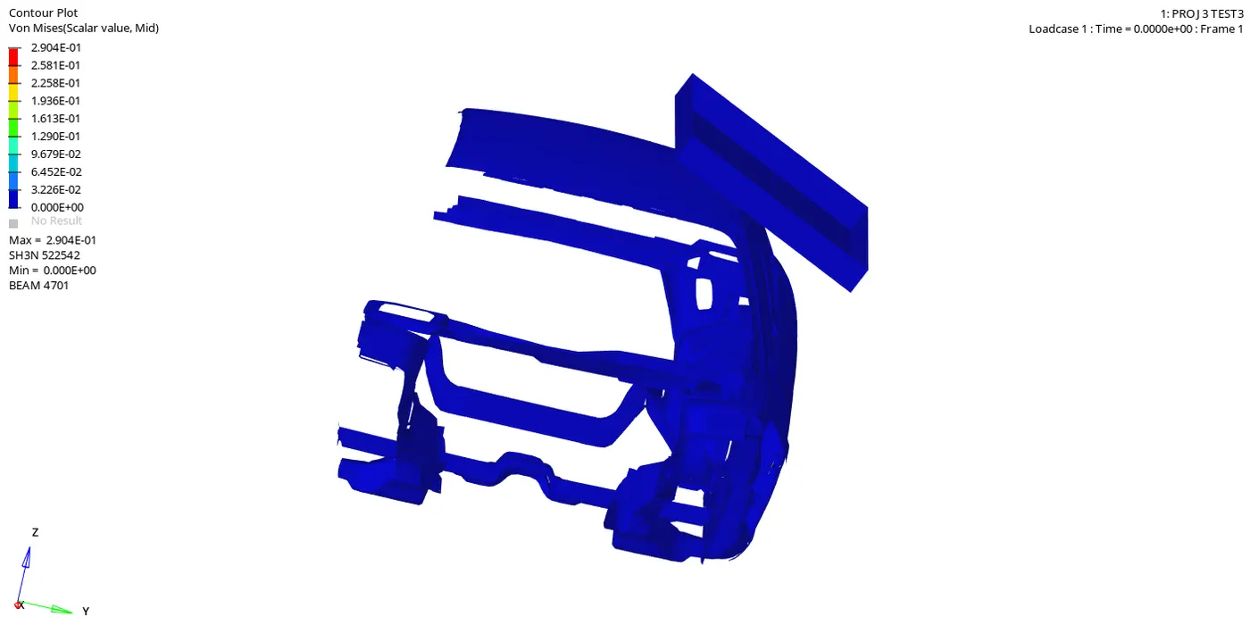
Von Mises stress is used to determine if a given material will fracture or yield. It is mostly used for ductile materials, such as metals. The von Mises yield criterion states that if the von Mises stress of a material under load is equal or greater than the yield limit of the same material under simple tension then the material will yield.
The max von mises stress is 2.904e-01 N/mm2.
GRAPH PLOT RESULTS :
ENERGY vs TIME GRAPH
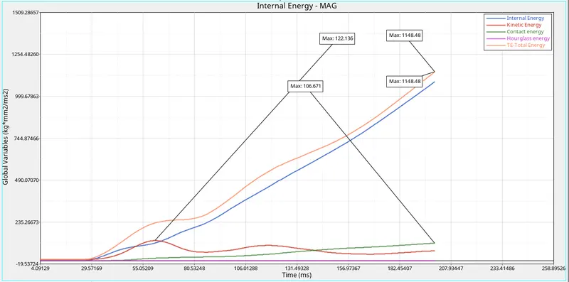
from the above graph we can see that From the start of the simulation, all the energies are in zero state but after 30ms (impactor hits the roof) the internal energy of the vehicle increases w.r.t time which says that the deformation in the elements is increasing continously .
whereas,kinetic energy was gradually increasing as the impactor was impacting the top surface of the roof after 60 ms the kinetic energy started recording in the plot and began decreasing with significant increase in internal energy with time.
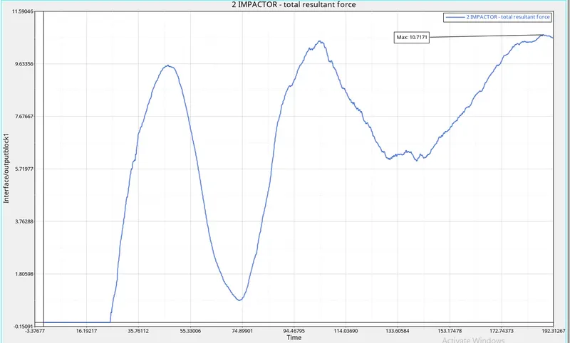
RESULTANT FORCE OF IMPACTOR
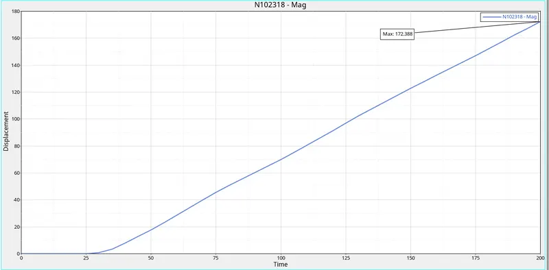
DISPLACEMENT OF NODE 102318 VS TIME GRAPH
- CROSS-PLOTTING - FORCE vs DISPLACEMENT CURVE
From HYPERGRAPH mode we make use of Cross-plot option to build a cross plot, we must have a Plot of the Force vs time of the contact interface between the Impactor and the car. And the second plot that we need is the Displacement of any one of the nodes on the car. To do this, we must build plots of that node in a separate window. Now in the third window, we must use the cross plot option and select (Shift+curve select) the displacement curve in the X-axis and the Force in the Y-Axis and create the plot.
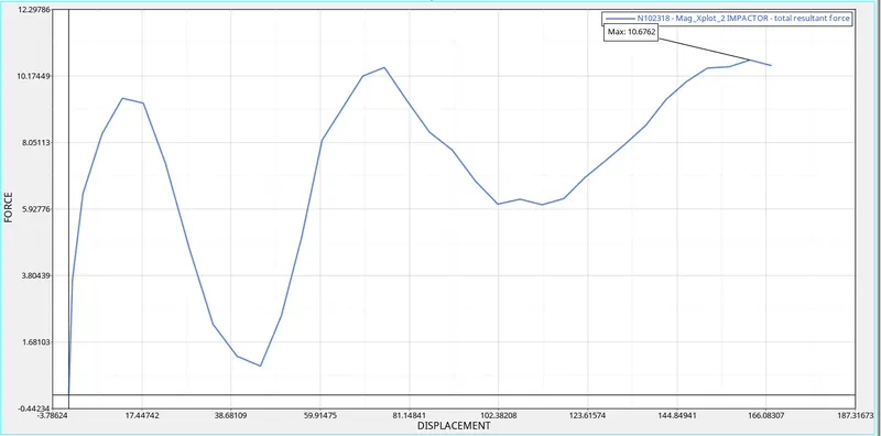
from the graph above we observed that the maximum force is of 10.67kN at dsiplacement value 167 mm of master node of rigid body which is in impactor.
- Check that the FMVSS 216 target load of 47,000 N (= 3 * GVW) has been met.
According to the new FMVSS 216 standards, the resisting force generated by the car structure must be at least 2.5 times the Unloaded Vehicle Weight (UWV) of test vehicle.
Here when we have calculated the total mass of the model it calculates value of 174kg,
To calculate total mass of the model we go to Tool>Mass calc>elements.
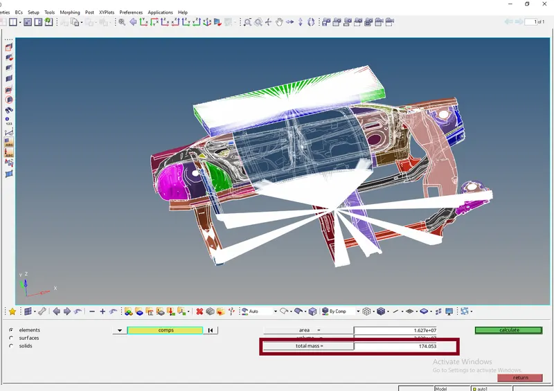
since this is mass of reduced model let us assume the full scale model mass is of 1400kg
now lets calculate the GVW i.e., Gross Vehicle to weight ratio i.e.,
GVWR=9.8*1400 = 13734
now we will multiply the GVW with 3 as a Factor of safety to check its value that wether its reaching the FMVSS standard or not
so,
Fres(resistive force)kN =3*GVWR
= 3*13734 = 41202 kN
Since our value is lesser than the specified value of 47,000N, we can conclude that the this condition has been satisfied and met properly.
CONCLUSION :
Finally,the given BIW was tested according to FMVSS 216 roof crush standards and we cheked if the FMVSS 216 target load of 47,000 N (= 3 * GVW) has been met so we can conclude that the this condition has been satisfied and met properly.