PWM Controlled Fan Load using DC motor
Aim : To model a fan type load in Simulink and to control its speed by using the PWM method
Theory :
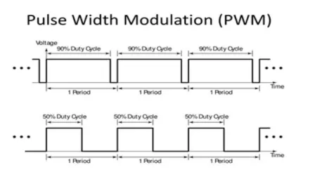
Pulse Width Modulation
The PWM or Pulse Width Modulation is a technique of minimizing the average power delivered by an electrical supply, by properly chopping it up into discrete parts. The average value of supply or voltage fed to the load (motor, light, device) is controlled by turning on and off the switch between supply and load. Here the switching On and Off is done at a fast rate.
Pulse width modulation is a great technique for controlling the amount of energy supplied to a load without dissipating the energy.
Mathematical formula :
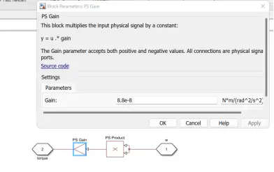
Load Torque proportional to square of speed (fan type)
T = K * w ^ 2
Model Explanation:
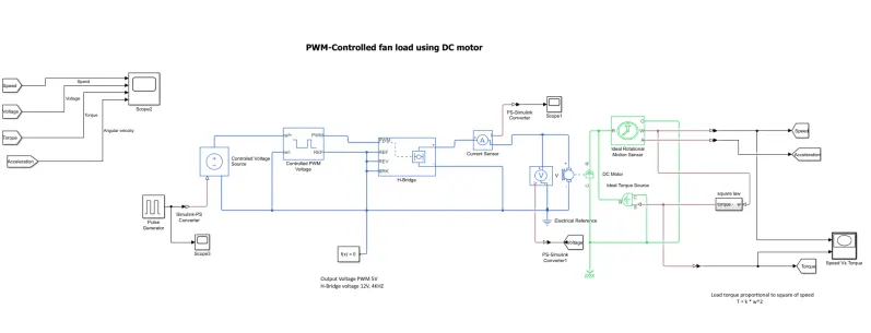
From simulation model we can see that the controlled voltage source input is given by pulse generator. After that this signal goes to H-bridge. This H bridge is used for change the direction of rotation of motor. It is basically driver circuit which drive the dc motor. Except for the PWM port, all of the H-Bridge block's input ports are connected to ground in this model. When the motor is on, the H-Bridge block connects the motor terminals to the power supply.
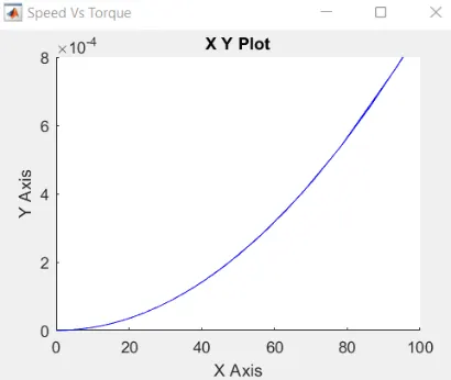
When the motor is off, the H-Bridge block acts as a freewheeling diode to maintain the motor current. Instead of using a Simulink physical model of a fan to analyse the output results, a fan type load equation(square law) was used. Using PWM technology, the fan's speed can be adjusted in accordance with the input voltage. Subsystem represents the fan load. We can represent the variation in speed and torque with respect to time in the scope block, but to observe the variation in speed and torque, we must look at the XY graph block.
DC Motor : Rated speed (at rated load) - 2500 rpm and no-load speed of 4000 rpm when run from a 12V DC supply.
PWM frequency - 4000Hz
Output Voltage PWM - 5V
H-Bridge voltage - 12V
Simulation Model:
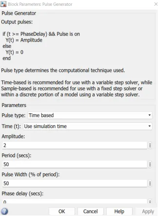
Pulse generator Block
Fan load (Subsystem)
Simulation Result:
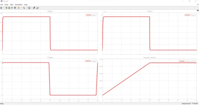
Speed Vs Torque graph
Observations : This model demonstrates how to control the dc motor fan load using the H-Bridge and Controlled PWM Voltage blocks.
Conclusion : Simulink was used to model and analyse the outcomes of a H bridge circuit used to control a PWM controlled DC motor. A fan's load torque characteristics are obtained.
Reference: https://skill-lync.com/student-projects/pwm-controlled-fan-load-using-dc-motor