Week - 4
Q.1. Implement control logic of a “washing machine” using Stateflow as per given sequence:
- If the power supply is available, the system gets activated
- If the Water supply is not available, stop the process & indicate through LED
- Soaking time should be 200s followed by Washing time of 100s.
- Then rinsing happens for next 20s & dryer runs for 50s
After all the processes have completed turn on the finished LED
Answer : First we have to create chart for "washing machine” using Stateflow as per given sequence
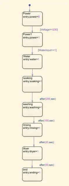
- Inside chart our first block is taken as a power, so as per conditions if power supply is avilable i.e. volatge >230 then signal pass through next block otherwise signal not passing to next block.
- After that the second conditions we have to implement i.e If the Water supply is not available, stop the process & indicate through LED (Waterinput==1).
- If water supply is avilable signal pass through next block soaking, then after 200sec it will go washing block.
- After washing 100sec of delay signal goto rinsing state, Then rinsing happens for next 20s & dryer runs for 50s and process is done.
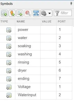
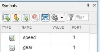
- We have to declare state input or output data by using symbol pan.
- Here input data is voltage, water supply and output data is soaking, washing, rinsing and dryer.
Simulations Model and Result
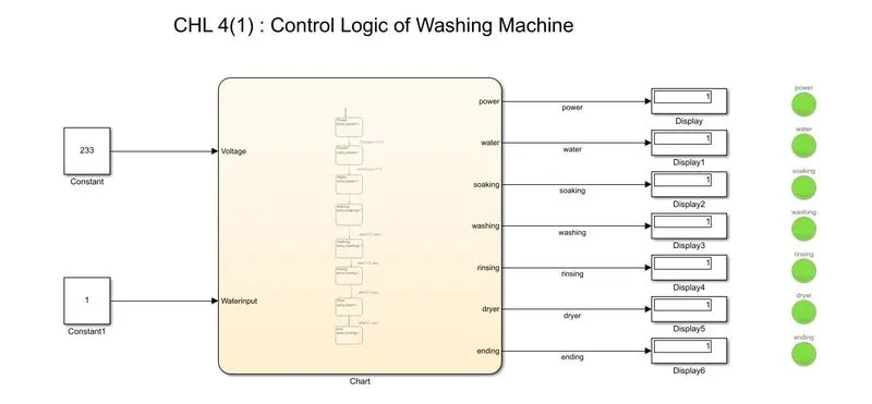
we can see from simulations diagram, each one display connected to lamp for understanding the state which is active when lamp show green color and deactive when lamp show red color. for eg here we can easily understand i.e constant block show voltage is 233 menas voltage is greater then 230 hence lamp will be glow.
Q2. Make a Simulink chart for the “Gear shift” logic as per below conditions:
Speed Range(kmph) Gear
0 to 15 1
16 to 25 2
26 to 40 3
41 to 60 4
Above 61 5
Give speed input while the simulation is running & display the gear number.
Answer : similarly like first case here also we create chart for Gear shift logic.
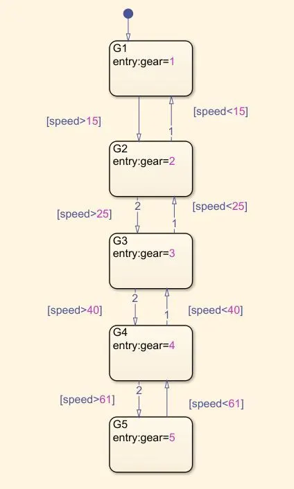
- First state block taken and define as G1 and apply conditions i.e speed range if less then 15kmph it will go through first gear otherwise move to second gear.
- Similarly for other four gear we had define oher conditions also. Here speed is input data and gear is output data.
- For varying the speed range we taken slider gain block and display the gear number at display block.
- Simulation run time should be given as a infinite.
Simulations Model and Result
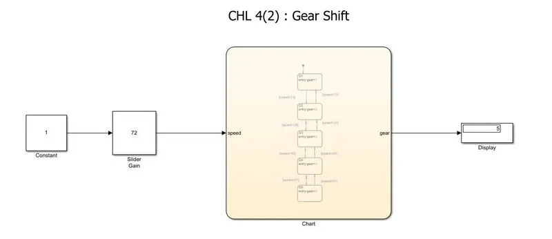
we can see from simulation dig. the slider gain show 72 means the speed range is above 61 hence at output display show gear 5.