Transient-state simulation of flow over a throttle body
Aim:
To perform a transient-state flow analysis over a throttle body and draw suitable conclusions.
Problem statement:
To perform a transient-state analysis over a throttle body, wherein the throttle plate is deflecting with respect to time about an axis. The throttle deflection with respect to time is as follows
- From 0 to 2ms the valve should rotate by 25 degrees.
- From 2 to 4ms it should stay at 25 degrees.
- After which by 8ms the valve should get back to its original position.
Geometry:
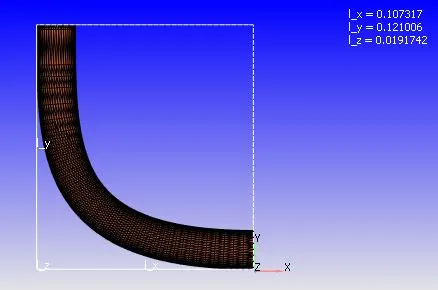
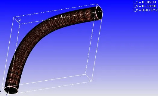
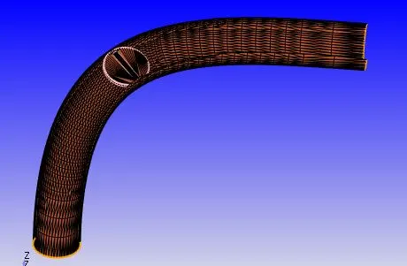
A butterfly valve throttle body is used for this simulation. Here a butterfly valve is placed inside a circular cross-section pipe with having an elbow configuration like as shown above. The faces of the geometry are given different names(inlet, outlet, wall, and throttle_wall) so that the boundary conditions can be provided easily.
Case setup:
1. Mesh size:
0.002m (In all three coordinate axes)
Three embedded layers of scale 3 applied near the throttle plate
2. Type of simulation: Transient-state simulation with zero reactions and only air(77% N2, 23% O2) as the medium of flow.
3. Boundaries:
Inlet: Inflow boundary condition with pressure inlet (150000Pa).
Outlet: Outflow boundary condition with pressure outlet (101325Pa).
Wall: Stationary wall with no-slip boundary condition.
Throttle: Moving wall with no-slip boundary condition.
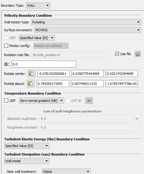
The axis and center of rotation can be found using the 'measure arc normal' or 'measure triangle normal' option. Just click on three vortices or a triangle where we want to define the center and axis of rotation and the results will be displayed in the 'message log', which can be copied and pasted in the above dialog box.
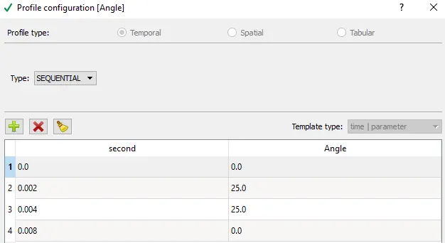
The rotation rate file is given above. At 0s, deflection is zero. At 2ms, the throttle plate will deflect to 25 degrees and will remain in this position up to 4ms. The throttle plate will return to its original position (zero degrees deflection) by 8ms.
4. Solver properties:
Start time= 0s
End time= 0.01s
The end time is decided from the results obtained in the steady-state simulation. From the steady-state simulation, the average velocity at the inlet was found to be 104.4m/s. Let the average length of the pipe be 0.2m. Therefore, the time taken by the air to reach the outlet from the inlet once is 1.915e-3s. the time taken by the air to reach the outlet from the inlet five times is 9.578e-3s. Hence, the end time is taken as 0.01s(10ms). Also, the end time cannot be below 8ms since the throttle plate is still in motion.
Minimum time step = 1e-6 sec
Maximum time step = 1 sec
Maximum convection CFL limit(final stage)= 0.5
5. Turbulence model used:
RNG k-epsilon turbulence model
Solution:
Mesh:
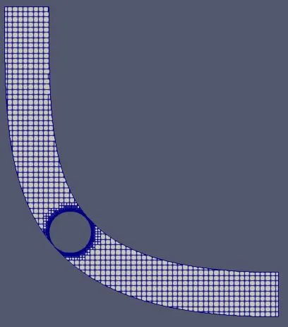
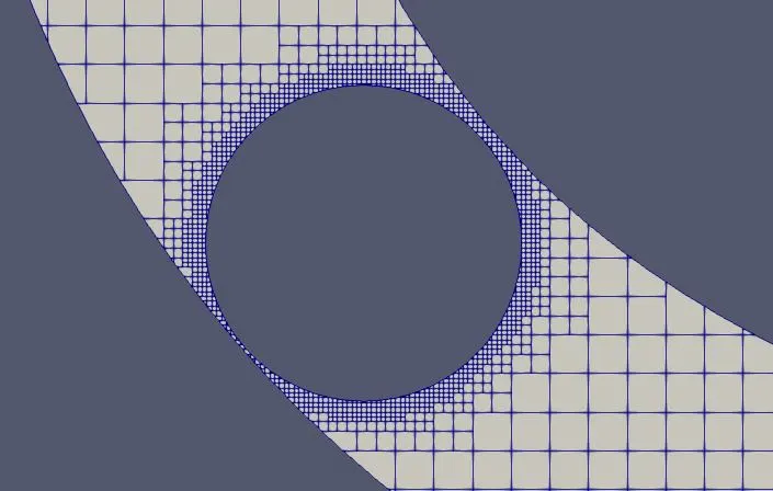
The Mesh element size is 0.002m (all three coordinate axes). Three embedded layers of scale 3 applied near the throttle plate. Since the dynamic mesh is used, the total number of mesh elements change with respect to time, as the fluid geometry changes due to throttle plate deflection.
Velocity contours:
Pressure contours:
Velocity streamlines:
Line plots:
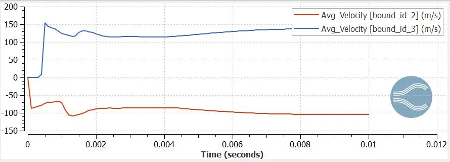
Average velocity:
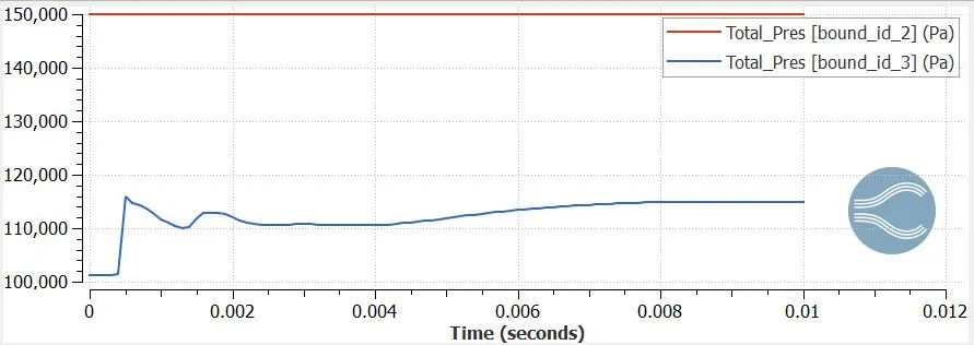
Total pressure:
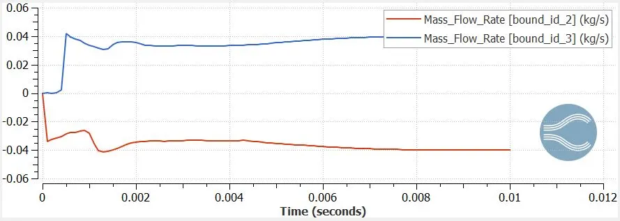
Mass flow rate:
Cell count:
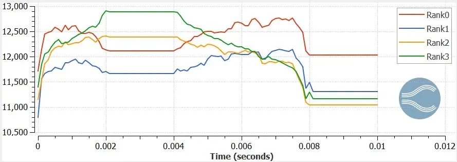
The problem was solved using 4 processors. Since there were moving parts in the geometry, a dynamic mesh was generated. Hence, the total number of mesh elements changes with respect to time. We can see that since the throttle valve remains in the 25 degrees angle position from 2-4ms, and in zero degrees angle position after 8ms, the mesh geometries remain unchanged for that time step. For the remaining time steps, the mesh geometry, and hence the total number of mesh elements change with respect to time.
Conclusions:
- By performing the transient state analysis on the throttle body, we can clearly see the effect of the deflection of the throttle valve on the fluid properties. When the throttle plate deflection is at 25 degrees, the mass flow rate of the fluid at the outlet is comparatively low than at throttle valve deflection of 0 degrees. This is clearly shown in the mass flow rate line plot, where the mass flow rate of the fluid is higher at the time above 8ms compared to at time 2-4ms.
- Similarly, the velocity of the fluid at zero degrees throttle deflection is higher than at 25 degrees throttle deflection at both the inlet and the outlet. The total pressure at the outlet increases as the throttle plate deflection is reduced from 25 to 0 degrees.
- Since the throttle plate of this geometry is deflecting with respect to time, a new mesh must be generated for each new position(dynamic meshing). Hence the total number of mesh elements in the geometry changes with respect to time as the throttle plate is deflected. Here 4 processors are used to solve the problem, which is given a certain number of cells to handle. This number changes as the geometry changes with respect to time.