Steady state simulation of flow over a throttle body
Aim:
To perform a steady-state flow analysis over a throttle body and draw suitable conclusions.
Theory:
In a traditional spark-ignition gasoline engine, the throttle body is the part of the air intake system that controls the amount of air that flows into an engine's combustion chamber. It consists of a housing unit that contains a throttle plate that rotates on a shaft. When the accelerator is actuated, the throttle plate opens and allows air into the engine. When it is released, the throttle plate closes and effectively chokes off the airflow into the combustion chamber. This process effectively controls the speed of the engine and ultimately, the speed of the vehicle.
Typically, the throttle body is located between the air filter and the intake manifold. It contains the delicate throttle system which controls a key component of spark ignition: airflow. Part of the atomization process, airflow helps regulate the air-fuel mixture ratio required to ignite an engine. The primary regulator for throttle pressure comes in the form of the throttle body temperature sensor, which measures the temperature of the air-fuel mixture entering the fuel injection system of your car. This necessary regulation helps spark ignitions generate the most fuel efficiency. The airflow is regulated by the driver via pressing on the acceleration pedal inside the vehicle. This reacts to a sensor on the throttle bottle which tells it to allow more air into the combustion chamber, increasing power output. This makes the car, in turn, go faster.
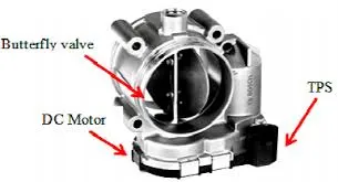
[Ref: ThoughtCo "What Is a Throttle Body and How Does It Work?" By Christine & Scott Gable, https://www.thoughtco.com/what-is-a-throttle-body-85383]
Geometry:
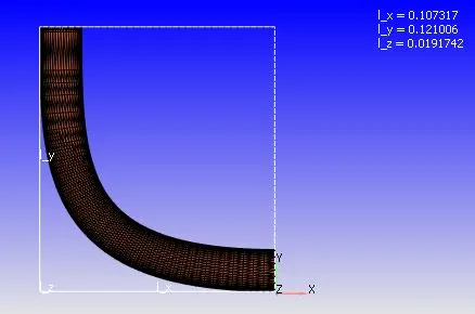
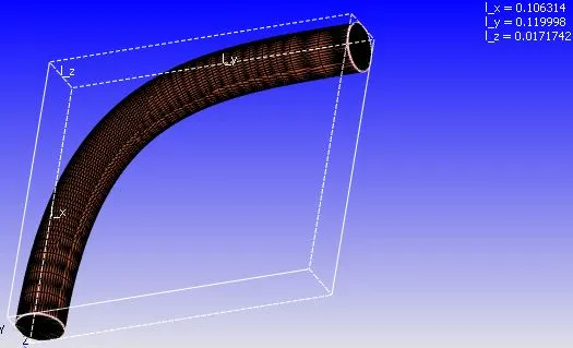
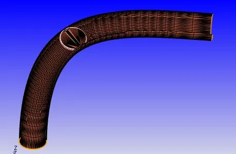
A butterfly valve throttle body is used for this simulation. Here a butterfly valve is placed inside a circular cross-section pipe with having an elbow configuration like as shown above. The faces of the geometry are given different names(inlet, outlet, wall, and throttle_wall) so that the boundary conditions can be provided easily.
Case setup:
1. Mesh size:
0.002m (In all three coordinate axes)
Three embedded layers of scale 3 applied near the throttle plate
2. Type of simulation: Steady-state simulation with zero reactions and only air(77% N2, 23% O2) as the medium of flow.
3. Steady-state monitor properties:
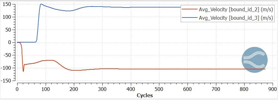
a) Average velocity at the outlet
b) Average mass flow rate at the outlet
4. Boundaries:
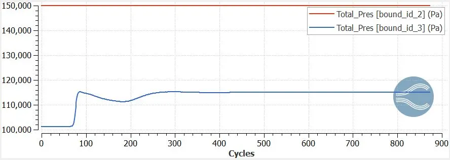
Inlet: Inflow boundary condition with pressure inlet (150000Pa).
Outlet: Outflow boundary condition with pressure outlet (101325Pa).
Wall: Stationary wall with no-slip boundary condition.
Throttle: Stationary wall with no-slip boundary condition. This boundary condition is provided since this analysis is performed using a steady-state solver, which estimates the flow once the flow has reached its steady-state. Hence the throttle plate is fixed at zero degrees deflection and the flow simulation is performed on it.
5. Solver properties:
Minimum Cycles = 0
Maximum Cycles = 15000
Minimum time step = 1e-6 sec
Maximum time step = 1 sec
Maximum convection CFL limit(final stage)= 0.5
6. Turbulence model used:
RNG k-epsilon turbulence model
Solution:
Mesh:
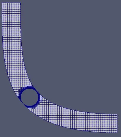
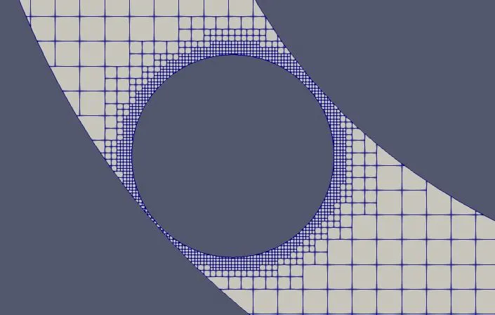
The Mesh element size is 0.002m (all three coordinate axes). Three embedded layers of scale 3 applied near the throttle plate. A total of 45068 mesh elements were generated.
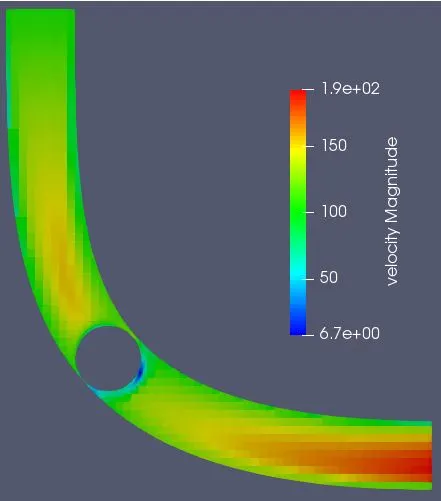
Velocity contours:
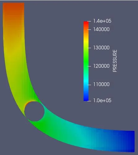
Pressure contours:
Velocity streamlines:
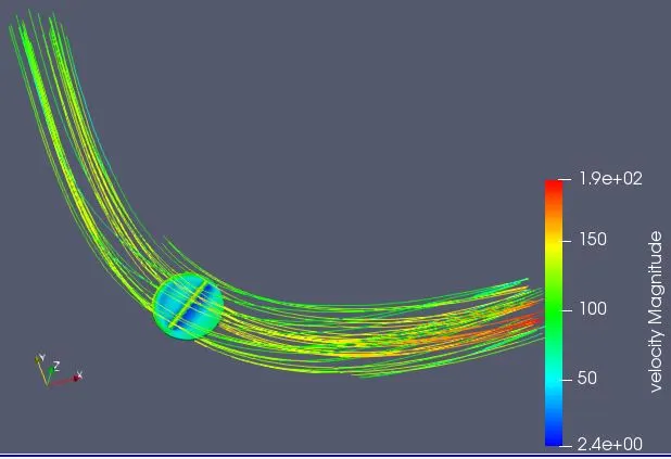
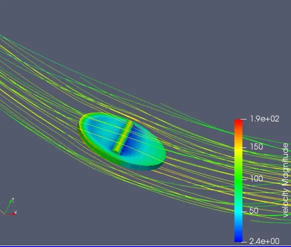
The above diagrams show the velocity streamlines over the throttle plate once it has reached its steady state when the throttle plate deflection is zero drgrees.
Line plots:
Average velocity:
Total pressure:
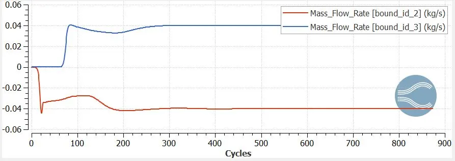
Mass flow rate:
Cell count:
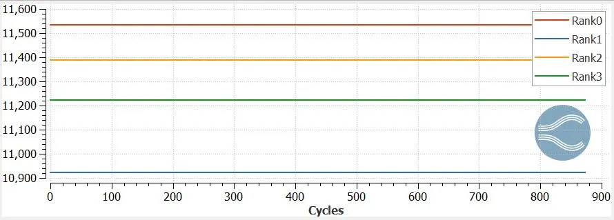
There were a total of 45068 mesh elements(cells) which were solved using 4 processors. The above line plot shows the cell distribution between different processors. The number of mesh elements solved using rank0, rank1, rank2, and rank3 processors are 11534, 10923, 11388, and 11223 respectively.
Conclusions:
- The main objective behind performing the steady state analysis on the throttle body is to find the fluid properties with zero degrees throttle valve deflection once it has reached steady state. Since this is steady state analysis, the throttle valve cannot be deflected as a function of time. To do so, traansient-state analysis must be performed. The flow properties obtained using the steady-state analysis can be used to derive transient state analysis parameters like start and end time, time step etc.
- The throttle valve is used to regulate the flow of air(or any other fluid) entering a domain. For example air intakes for IC engines.