Project - Speed Control of a Direct Current (DC) motor
DC Motor Modelling
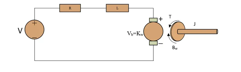
J=moment of inertia of rotor
B=Damping constant
R=Armature resistance
L=Armature Inductance
Vb=Back EMF Constant
Kt=Motor Torque constant
V= Voltage
Motor torque T =Kt*I
Back EMF Vb=kb*w
For finding equation
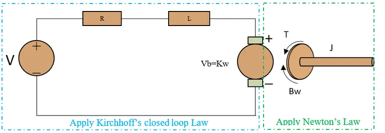
Applying Kirchhoff's closed loop law
we get
L dI/dt+ RI=V-kb dθ/dt (a)
applying Newton's Law
we get
J `(d^2θ)/dt^2`+B dθ/dt=kt*I (b)
converting the above equations to s domain
Ls I(s) +R I(s)=V(s)-kb s θ(s) (c)
I(s)[Ls+R]=v(s)-kb s θ(s)
I(s)=[V(s)-Kb s θ(s) ]/Ls+R (d)
Js^2 θ(s)+B sθ(s) =KT*I(s) (e)
w(s)=s θ(s) =KT*I(s)/Js+B (f)
substitute I(s) value in equation (e)
J s^2 θ(s) +B s θ(s) =KT* V(s)-Kb s θ(s)/Ls+R (g)
s θ(s) [(Js+B)*(Ls+R)]=KT V(s)-KT*Kb s θ(s)
s θ(s) [(Js+B)*(Ls+R)] + KT*Kb s θ(s)= KT V(s)
s θ(s) [(Js+B)*(Ls+R) + (KT*Kb)]= KT V(s)
Transfer function of output angle θ(s) to the input voltage V(s) given by
Ga(s)= θ(s) /V(s) =KT/(s[(Js+B)*(Ls+R) + (KT*Kb)]) (h)
Transfer function of angular velocity w(s) to the input voltage V(s) given by
Ga(s)=w(s)/V(s)=KT/[(Js+B)*(Ls+R) + (KT*Kb)] (i)
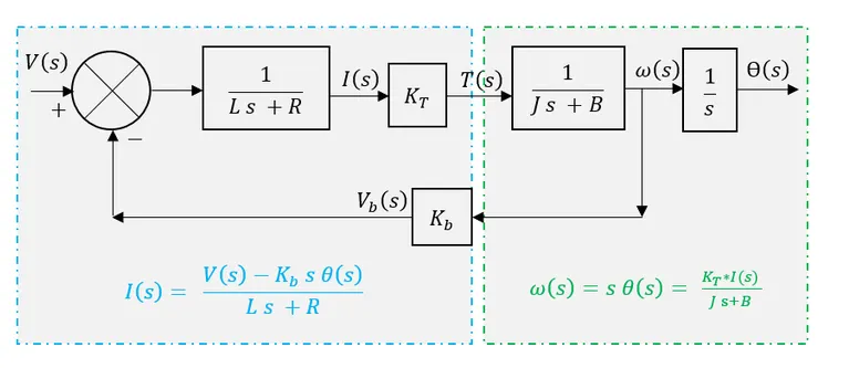
modelling of DC motor is shown in figure below
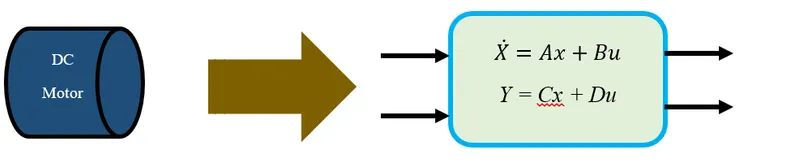
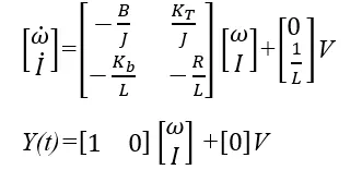
State space equations for the dc motor
State equations will now be derived by using equations (a) and (b)
dI/dt=-R/L*I +1/L*V-Kb/L* dθ/dt
dI/dt=-R/L*I +1/L*V-Kb/L*w
dw/dt=-B/J*w+1/J*KT I
Y(t)=w= dθ/dt
A state-space representation of the DC motor from above equations
%parameters of DC motor design
J=0.01;%inertia
b=0.1;%friction
km=0.01;%back emf
kt=0.01;%torque
Ra=1;%armature resistance
La=0.5;%armature inductance
%design of PID controller
A=[-b/J kt/J;-km/La -Ra/La];
B=[0;1/La];
%placement of poles
fn=1.0;
wn=2*pi*fn;
zeta=0.5;
p1=-zeta*wn+wn*sqrt(zeta^2-1);
p2=-zeta*wn-wn*sqrt(zeta^2-1);
P=[p1;p2];
K=place(A,B,P);
ki=0;
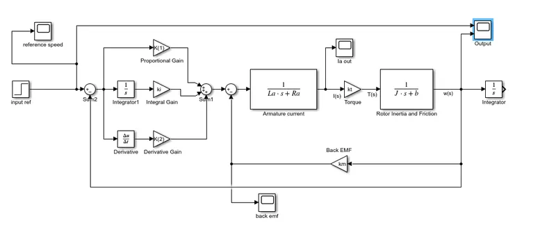
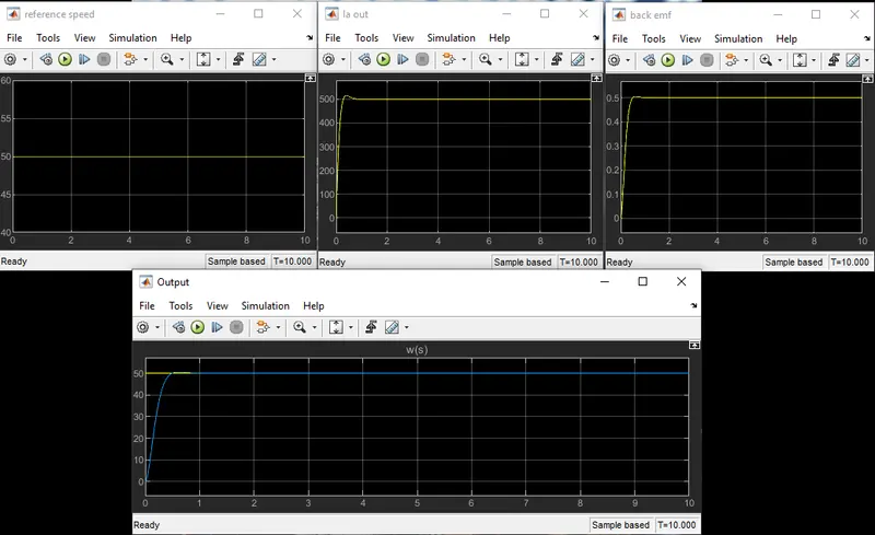
Reference is taken as speed which is 50 and first ki is taken as zero then after the first run changed the value of ki and found the suitable value to be 55 and also changed the value of kp kd so that the angular velocity is controlled.The value of kp and kd firstly was obtained by using the PLACE command from matlab and for getting the desired output we have changed the value of kp to 40 and kd to 2.
simulink model:
output:
Stability of a dynamic system
Stability of a dynamic system can be found out using pz map
k_dc=1;%the dc gain of the system is 1
s=tf('s');
G1=k_dc*wn^2/(s^2+2*zeta*wn*s+wn^2);
G1 =
39.48
---------------------
s^2 + 6.283 s + 39.48
Continuous-time transfer function.
pzmap(G1,'r');grid;
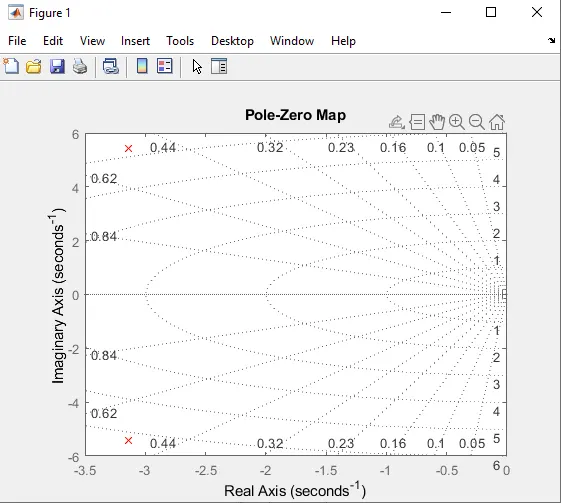
so from the pz map it is found that the poles are lying on the left half of the s plane.so the above system is stable.
Conclusion:
Designed a PID controller for regulating the speed of a DC motor.Initially the value of kp and kd are found from PLACE command and ki is taken as zero ,so by changing the values we got the desired output.
we have changed the reference speed to different values and found that ouput changed to the given reference speed and hence found that control law is obeyed.