Project - Speed Control of a Direct Current (DC) motor
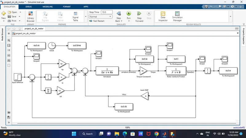
1. A Simulink model for the DC motor,Using the Proportional, Integral, and Derivative (PID) control
design . which I had learned from simulink basic, which they given in motor schematic diagram,
by applying KVL i find the solution which i had been solved here,
J= Moment of Inertia of Rotor
Bc= Damping Constant
R= Armature resistance
L= Armature inductance
V = Back emf constant
K = Motor Torque constant
V= Voltage,
Kirchhoff's voltage law states that the voltage around a loop equals the sum of every voltage drop in the same loop for any closed network and equals zero.
Vs = Raia + Ladia/dt + Vb
Vb = km*dtheta/dt
we know laplace transfer function is output by input of the give equation or model
therefore ;
ws/Vs(s) = kt/JLas^2 + (JRa + BLa)s + (BRa + ktKm)
What is PID Controller?
- A proportional–integral–derivative controller (PID controller or three-term controller) is a control loop mechanism employing feedback that is widely used in industrial control systems and a variety of other applications requiring continuously modulated control.
- The proportional integral derivative controller produces an output, which is the combination of the outputs of proportional, integral, and derivative controllers. The feedback from the plant whichever is a controllable parameter is given as input to the PID controller and the processed error is minimized to get the desired output if tuning of the parameter is done
optimally. The mathematically PID controller can be defined by the following equation where e(t) is the error signal with respect to time, K , K and K are PID constants.
To understand PID controller design one needs tounderstand the importance of P, I and D in control dynamics.
For our case, the transfer function is determined from the constants of motor and state space equations,
% This file contains parameters for DC motor design
J=0.01; % Inertia
B=0.1; % friction
Km=0.01; %back emf
Kt=0.01; % torque
Ra=1; %resistance
La=0.5; %inductance
%% Design of PID controller
A=[-B/J Kt/J; -Km/La -Ra/La];
b=[0 ; 1/La];
% Placement of Poles
fn=1;
wn=2*pi*fn;
zeta=0.5;
p1=-zeta*wn+wn*sqrt(zeta^2-1);
p2=-zeta*wn-wn*sqrt(zeta^2-1);
P=[p1;p2]
K=place(A,B,P)
From the above script we can determine the controller gain parameters Kp and Kd, from the location of poles p1 and p2 using
‘place’ command or ‘acker’ command in MATLAB. The Ki is tuned manually and Kp, Kd values are taken from the place
command.
PID Controller Design for DC Motor
To design a closed loop control scheme for a DC motor the following changes need to be done in the model in the previously created model.
Speed is the controllable parameter, so we will set the reference speed in step block as 10,20, 40 whichever you want.
Subtract the actual speed from the reference speed to generate the error signal e(t) Add Kp as K(1) and Kd as K(2) parameter determined from place command (K=place(A,B,P)). (use gain block to mention values of Kp, Kd, and Ki)
The feedback for Kd is provided from the output current of the plant/model OR we can take feedback
Add Ki manually with gain and integrator block and tune different values of Ki and check the impact of it on results.
To check the location of poles on the s-plane from MATLAB the following command (‘pzmap ’-pole zero placement or mapping) can be used in continuation to the above script. You can see two crosses in red indicate complex poles lying on the left hand of the plane which indicate it is a stable system.
k_dc=1; % the DC gain of the system is 1
s = tf('s');
G1 = k_dc*wn^2/(s^2 + 2*zeta*wn*s + wn^2);
pzmap(G1,'r')
we can use diffrent input speed to control the out put ,
in this project i learned how to regulate speed of DC Motor and also how to apply the kirchoffs voltage law to the circuit and after that we have to apply the laplace transformer finction to that which we can used the place command to place the value of A,B,p
after this we used matlab m file to save the equation which wil help to save the data on work space
This is the Model which I had build By using the Matlab and Simulink Basic,
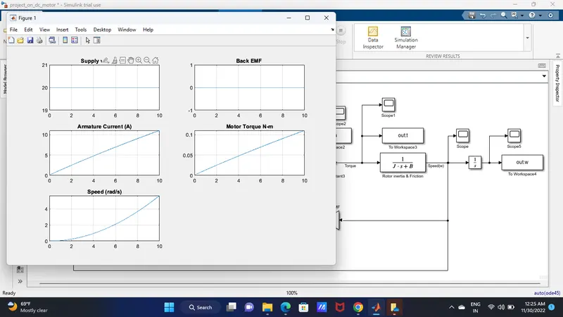
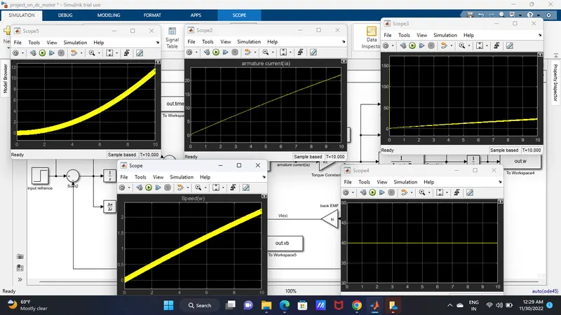
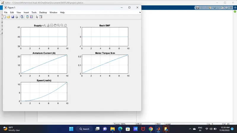
If we change the refrence input the out put will change accordingly that,which i had absorved in this project and also i learned so many things of simulink in this project and i absorved the changes and regulating the speed of DC Motor.
and also I attached my M_file to this which helps u to change input value and check the respone of given model below,
Scope are used to see the graphically response directly,