Project 1
Project on double-acting actuator model using Simscape Multibody and Simscape components.
Aim :
- Develop a double-acting actuator model using Simscape Multibody and Simscape components.
Objective :
- The mechanical system of the cylinder needs to be built using Simscape Multibody library components/blocks, and the hydraulic system needs to be modeled using Simscape library physical components.
Theory :
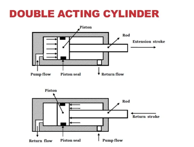
The following Cylindrical Model Schematic shows the three different configurations of the piston
How the Double Acting Hydraulic actuator works -
Double-acting hydraulic cylinders have a Cylindrical housing and one piston. When hydraulic oil is supplied to its cap end port, hydraulic pressure force will be applied over the piston and the end cylinder will be extended. During the extension of the piston hydraulic oil at the rod, the end side will be pushed out and directed towards the reservoir.
For the returning stroke, the hydraulic direction is reversed with the help of the direction control valve. During the returning stroke hydraulic oil is supplied to the rod end side and hence piston is retracted. During the retracting of the piston cap end, oil is directed towards the reservoir. hence the double-acting hydraulic actuator operated in both the directions
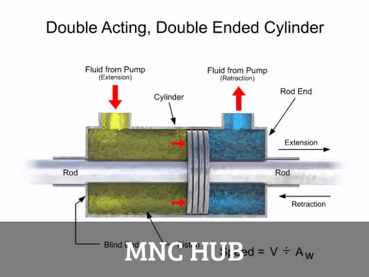
The extra port also allows more control of the piston during retraction and ensures it always returns back to its starting point;
The model which I have been created here With the help of both Mechanical and hydraulic system.
This is Main Model of This Project;
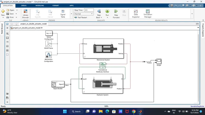
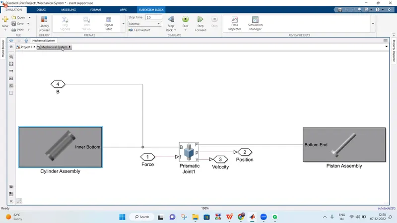
This is the Mechanical system Model ;
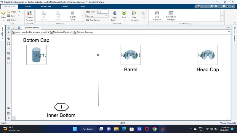
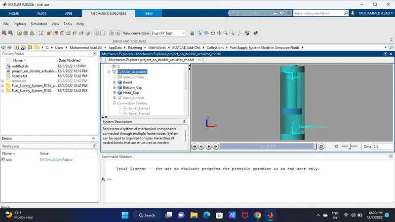
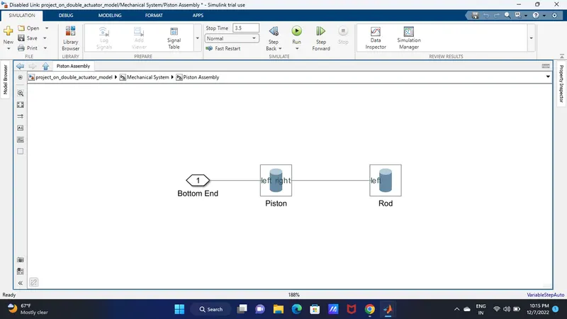
Above is cylinder assembly and below is the piston assembly;
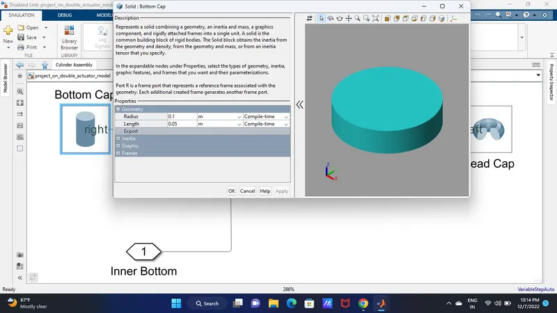
This is the bottom cap which I have been created from cad file,
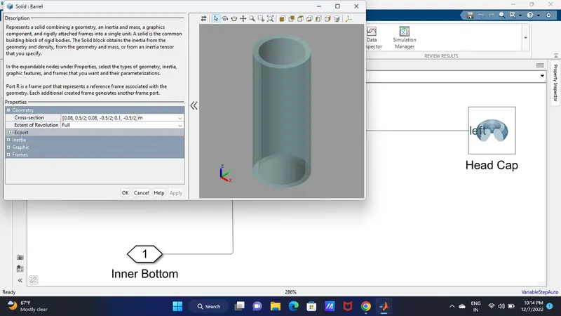
This is the barrel,Represents a solid combining a geometry, an inertia and mass, a graphics component, and rigidly attached frames into a single unit. A solid is the common building block of rigid bodies. The Solid block obtains the inertia from the geometry and density, from the geometry and mass, or from an inertia tensor that you specify.
Port R is a frame port that represents a reference frame associated with the geometry. Each additional created frame generates another frame port.
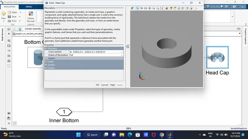
This head cap,Represents a solid combining a geometry, an inertia and mass, a graphics component, and rigidly attached frames into a single unit. A solid is the common building block of rigid bodies. The Solid block obtains the inertia from the geometry and density, from the geometry and mass, or from an inertia tensor that you specify.
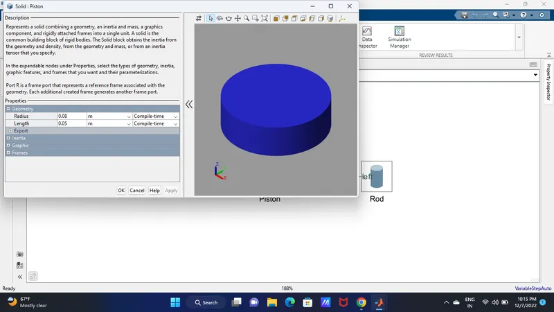
This is piston,Represents a solid combining a geometry, an inertia and mass, a graphics component, and rigidly attached frames into a single unit. A solid is the common building block of rigid bodies. The Solid block obtains the inertia from the geometry and density, from the geometry and mass, or from an inertia tensor that you specify.Port R is a frame port that represents a reference frame associated with the geometry. Each additional created frame generates another frame port.
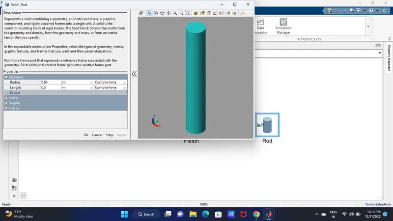
This is piston rod,
Represents a solid combining a geometry, an inertia and mass, a graphics component, and rigidly attached frames into a single unit. A solid is the common building block of rigid bodies. The Solid block obtains the inertia from the geometry and density, from the geometry and mass, or from an inertia tensor that you specify.
In the expandable nodes under Properties, select the types of geometry, inertia, graphic features, and frames that you want and their parameterizations.
Port R is a frame port that represents a reference frame associated with the geometry. Each additional created frame generates another frame port.
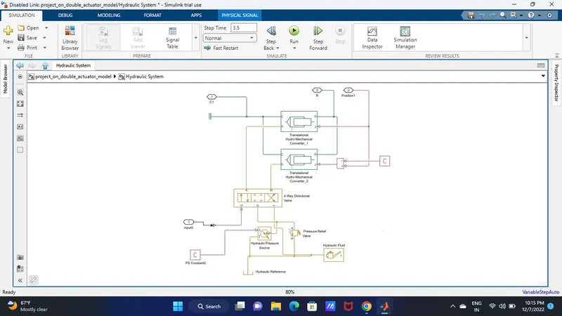
This is hydraulic system, we have used in this so many hadraulic system like Transistional hydraulic converter, 4 way directional valve ,hydraulic fluid and hydraulic pressure etc.
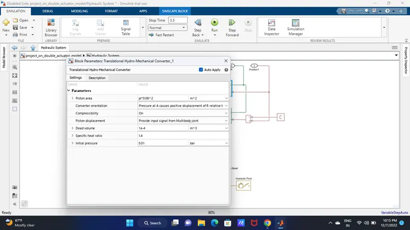
The block models an ideal transducer that converts hydraulic energy into mechanical energy in the form of translational motion of the converter output member. Fluid compressibility can be accounted for and the pressure variation due to density fluctuations dynamically solved. This does not require the addition of a chamber block.
Port A is a hydraulic conserving port associated with the converter inlet. Ports R and C are mechanical translational conserving ports associated with the rod and the body of the converter, respectively. When fluid compressibility is on, the piston displacement can be calculated internally or be set by the physical signal input port p. The piston displacement is defined to be zero when the volume is equal to the dead volume.
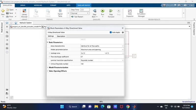
This is 4 way directional valve,
This block models the basic option of the 4-way directional valve in a hydraulic network. To parameterize the block, 3 options are available: (1) maximum area and control member stroke, (2) the table of valve area vs. control member displacement, and (3) the pressure-flow rate characteristics.
Ports P, T, A and B are hydraulic conserving ports associated with the valve inlet, outlet, and actuator terminals, respectively. The control member displacement is set by the physical signal input S. A positive displacement opens the connections between ports P-A and B-T and closes the connections between ports P-B and A-T.
Hydraulic pressure and hydraulic fluid.
The block represents an ideal source of hydraulic energy that is powerful enough to maintain specified pressure at its outlet regardless of the flow rate consumed by the system. Block connections T and P correspond to the hydraulic inlet and outlet ports, respectively, and connection S represents a physical signal port. The pressure differential across the source is directly proportional to the control signal.
The block assigns working fluid for all components assembled in a particular loop. The loop detection is performed automatically and the block is considered as part of the loop if it is hydraulically connected to at least one of the loop components. The block offers wide selection of fluids to choose from. The custom fluid is assigned with the Custom Hydraulic Fluid block from the Simscape foundation library. If neither Hydraulic Fluid nor Custom Hydraulic Fluid block is connected to the loop, the default properties of the Custom Hydraulic Fluid block are assigned.
Pressure relief valve,
This block represents a hydraulic pressure relief valve as a data sheet-based model. The valve remains closed while pressure at the valve inlet is lower than the valve preset pressure. When the preset pressure is reached, the value control member is forced off its seat, thus creating a passage between the inlet and outlet. Some fluid is diverted to a tank through this orifice, thus reducing the pressure at the inlet. If this flow rate is not enough and pressure continues to rise, the area is further increased until the control member reaches its maximum.
Connections A and B are hydraulic conserving ports. The block positive direction is from port A to port B.
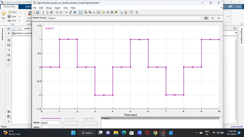
And we so many others mechanical and hydraulic system in this project , if we give the input we see the changes in different in out some graphs are attached here,
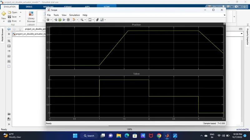
This is input signal,
Thankyou .