Project - Speed Control of a Direct Current (DC) motor
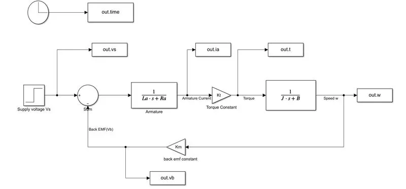
Q.1) In this project, a Simulink model for the DC motor will be first developed per the schematic shown in Figure Use the Proportional, Integral, and Derivative (PID) control design knowledge gained in the training to design, develop and test a controller to maintain a desired speed for the motor.
Answer-
- Here the Speed control of a DC motor is either done manually by the operator or by means of an automatic control device.
- This is different from speed regulation where the speed is trying to be maintained or regulated against the natural change in speed due to a change in the load on the shaft.
We know that the speed control of a DC motor can be classified into 2 types-
i) Armature Control Method.
ii) Field Control Method.
Simulink Model-
-This project is based on the speed control of a DC motor by using PID Controller.
Here first we need to create a Simulink model of the DC motor and make it a subsystem called the DC motor.
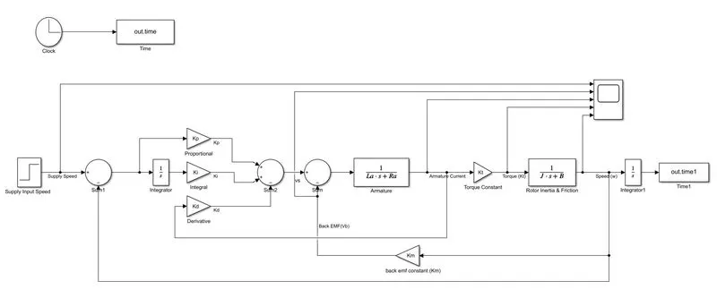
So next the subsystem of the DC motor is connected to the discrete PID controller which helps in maintaining the desired speed
Simulink Model For DC Motor-
MATLAB Script-
Here we consider the following parameters:
% This file contains the design parameter for modeling & design the DC motor.
J=0.01;  % Moment of inertia of motor in kg-m^2.
B=0.1;   % Motor viscous friction constant N-m-s.
Km=0.01; % Back EMF constant in V/rad/s.
Kt=0.01; % Motor Torque constant in N-m/Amp.
Ra=1.0;  % Resistances of Armature Circuit  in Ohm.
La=0.5;  % Inductances of Armature Circuit in Henry.

%Design of PID Controller.
A=[-B/J Kt/J;-Km/La -Ra/La];
C=[0;1/La];


% Pole Placement
fn=1;
wn=2*pi*fn;
zeta=0.5;
p1=-zeta*wn+wn*sqrt(zeta^2-1);
p2=-zeta*wn-wn*sqrt(zeta^2-1);
p=[p1;p2];
K=place(A,C,p);


%PID Design Parameter
Kp=38.3133;
Kd=-2.8584;
Ki=10;
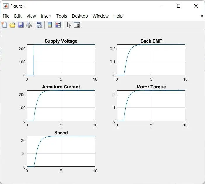
Output results for the DC_motor:
Now for the Design of the DC motor with a Discrete PID Controller:
We make the Dc motor as a Subsystem and PID Controller is Used to Control Desired Speed.
Scope Output-(Case -1)
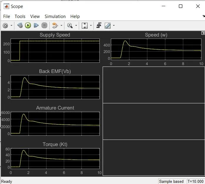
Case 2- To reduce the overshoot, the Kd value is increased to -0.9.
Scope Plot-
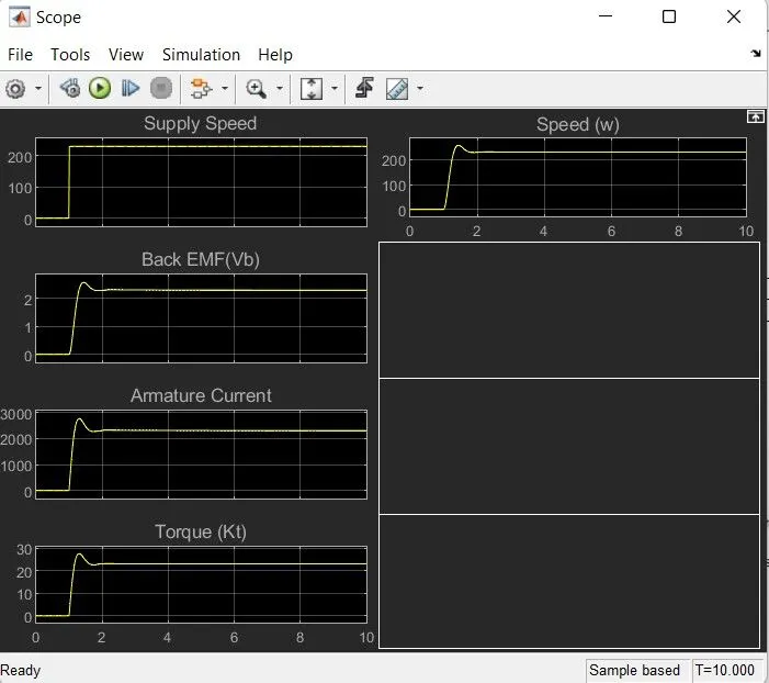
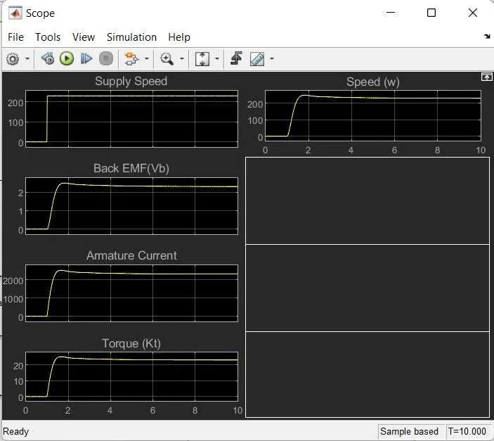
Case 3- To reduce the overshoot further, the Kp value is decreased(Kp=20).
Scope Plot-
Case 4- To further decrease the Ki value to 3.
Scope Plot-
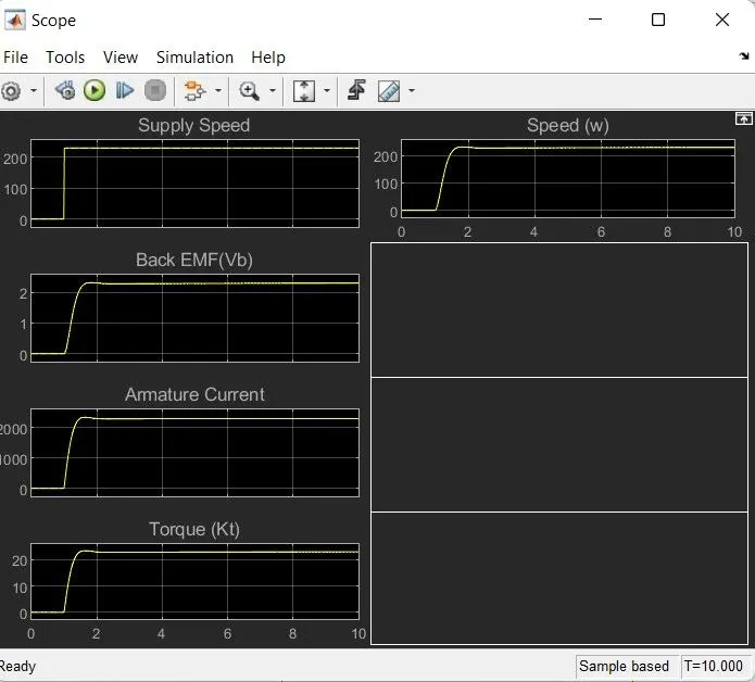
- Here by observing the above graphs, we change the desired speed by changing the value Ki=10 in case 1, decreasing the value of Kp=-0.9 in case 2 , in case 3 changing the value of Kp=20 and in case 4 changing the value of Ki=3.
- By observing all graphs, the overshoot is decreasing and in the last case, we can see that all parameter is steady.
- So by this, we can say that we maintained the desired speed of a DC motor
Conclusion-
we have designed In this project a Simulink model for the DC motor as shown in Figure. and also we Use the Proportional Integral and Derivative PID control design knowledge gained in the training to design develop and test a controller to maintain a desired speed for the motor.