Project 1
Develop a double-acting actuator model using Simscape Multibody and Simscape components. The mechanical system of the cylinder needs to be built using Simscape Multibody library components/blocks, and the hydraulic system needs to be modeled using Simscape library physical components.
Answer-
Aim: To Develop a double-acting actuator model using Simscape Multibody and Simscape components.
Theory:
To model the cylinder and piston, blocks to be used are:
Revolved solid (Simscape Multibody) and cylindrical solid (Simscape Multibody) blocks.
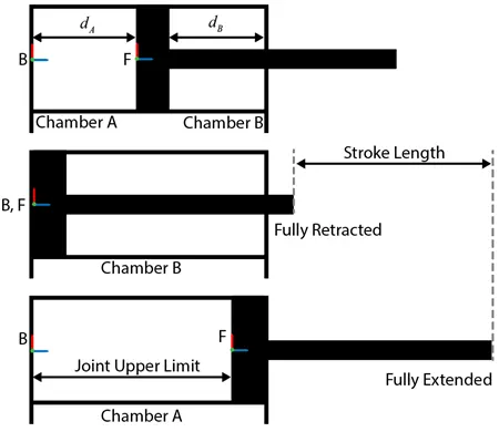
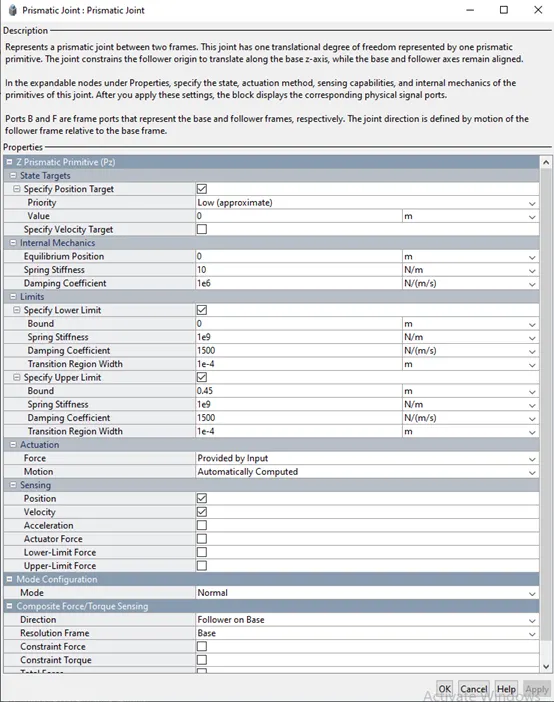
To provide the translational degree of freedom for the piston, use a Prismatic Joint (Simscape Multibody) block. To easily calculate the lengths of chambers A and B, you can attach the base frame (B) and follower frame (F) of the joint to the centers of the left inner surface of chamber A and the left surface of the piston, respectively.
Using this convention, the length of chamber A, dA, is the position output of the joint block, and the length of chamber B, dB, equals the difference between the stroke length and dA. To ensure that the piston does not travel beyond the ends of the cylinder, you can specify the upper and lower position limits of the Prismatic Joint block. The schematics show the cylinder in three configurations: half-retracted, fully retracted, and fully extended.
Double Acting Hydraulic Actuator System-
Double-acting hydraulic cylinders are linear hydraulic actuators that perform the movement in both directions using hydraulic pressure. The piston stroke in double-acting cylinders is much longer than in a single-acting cylinder.
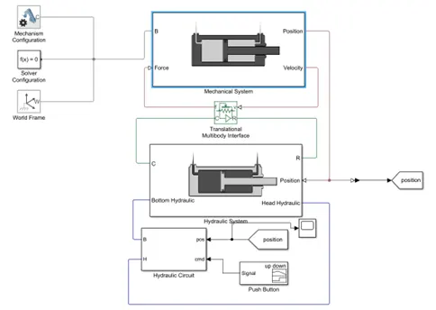
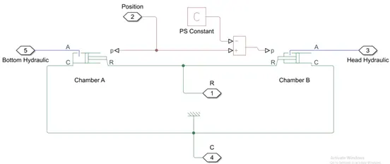
This figure shows the block diagram of the double-acting cylinder model described above. The example uses two translational mechanical converter(IL) blocks to model the chambers A and B of the cylinder. A
Translational Multibody Interface block connects the Translational Mechanical Converter (IL) blocks to the Prismatic Joint block. See connecting simscape networks to simscape multibody for details of how to use the Translational Multibody Interface block.
Working principle-
A hydraulic cylinder is a mechanical device that uses hydraulic power to create pressure. They are commonly used in various industrial applications and are also common in hydraulic pumps. They can be used in various ways, including as actuators or as lifting devices.
Double-acting hydraulic cylinder-
A double-acting hydraulic cylinder is a mechanical device that uses two chambers to regulate pressure. It has a control valve on each end that allows the user to selectively fill each chamber with pressurized fluid. This makes it possible to actuate the cylinder in two different ways: by pushing or pulling the lever in one direction (resembling the first action of a simple hydraulic cylinder), or by pushing or pulling the lever in the opposite direction (resembling the second act of a simple hydraulic cylinder).
In case of a hydraulic failure, the cylinder will retain the pressure in one of the chambers until the supply of oil is restored, thereby preventing any damage or injury. There are two types of double-acting cylinders:
- Double-acting cylinder with a piston rod on one side.
- Double-acting cylinder with a piston rod on both sides.
Double-acting hydraulic cylinder applications-
- Double-acting hydraulic cylinders are typically used in industrial processes that require a quick force.
- Double-acting cylinders are used for power steering and the more powerful the car the more power you need to be able to steer it.
- This type of cylinder is widely used in industrial equipment, such as cranes, forklifts, lifts, and other heavy-duty machines.
- Double-acting cylinders are used in hydraulic systems that raise and lower things such as landing gear, door hinges, etc.
- A very common use for a double-acting hydraulic cylinder is to open or close some kind of “flap” on an aircraft wing.
How does a double-acting hydraulic cylinder work-
A double-acting hydraulic cylinder has two distinct chambers: One chamber is filled with oil, and the other is empty. When the piston rod is retracted into the cylinder, the oil is forced into the empty chamber, and thus creates pressure. This pressure pushes the piston rod out, resulting in the extension of the cylinder. On the other hand, when the piston rod is pushed into the cylinder, the oil is forced into the chamber filled with oil, thus creating a vacuum. This vacuum pulls the piston rod into the cylinder, and thus retracts it. This action is reversed when you remove the force (that is when you let go of the rod). In this manner, you can use double-acting hydraulic cylinders to create the force necessary to push or pull something.
Mechanical system-

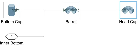
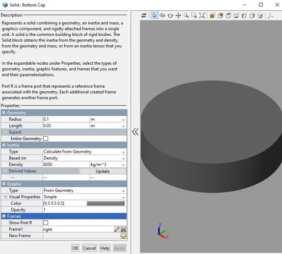
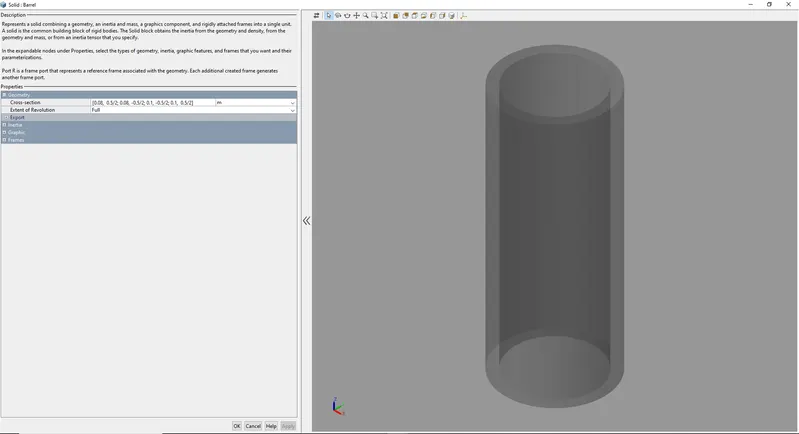
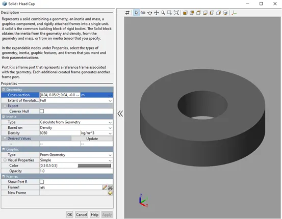
1.Cylinder Assembly-
Bottom Cap-
Barrel Cap-
Head Cap-
2.Prismatic Joint-
A prismatic joint is often called a slider — for example, a “crank-slider linkage.” This is a type of kinematic pair and an idealized way to describe how motions are constrained within machines.
There are several physical embodiments of a prismatic joint, such as slideways. Rectangular cross-sections may be used in combination with plain or rolling bearings to enable linear motion while preventing rotation about the axis of movement.
Hydraulic and pneumatic cylinders are typically modeled as prismatic joints although they may also permit rotation about their axis. Kinematic pairs are classified as higher pairs and lower pairs. Higher pairs involve point or line contact, such as a ball or roller that’s rolling over a surface. Lower pairs can be visualized as surface contact.
3.Piston Assembly-
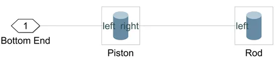
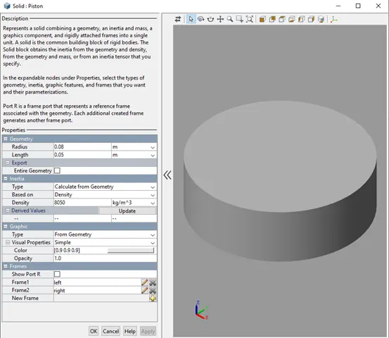
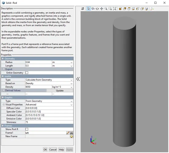
The inlet or outlet flow inside the barrel pushes the Piston or Plunger of hydraulic cylinders. When the Piston moves to either side of the cylinder, the Rod contracts or expands.
These are the parts of the basic hydraulic cylinders. More types of cylinders are more complex in their construction. However, these components are essential to almost all hydraulic cylinders, and it is good to know what they are and how they work.
Piston-
Rod-
Hydraulic system-
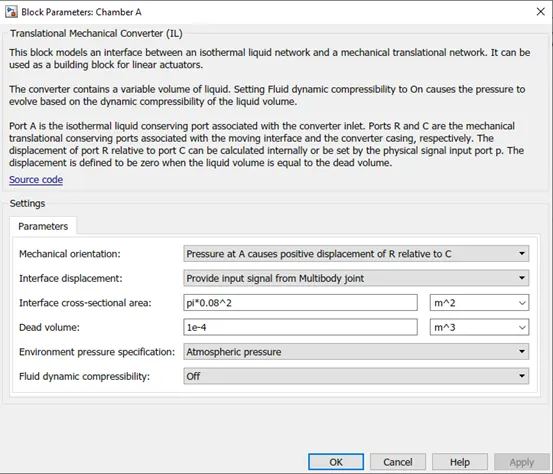
Chamber A-
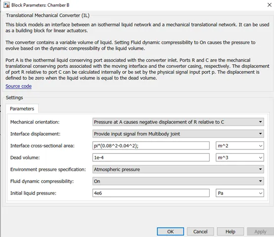
Chamber B-
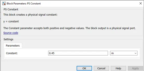
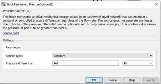
PS constant(C)-
Hydraulics-
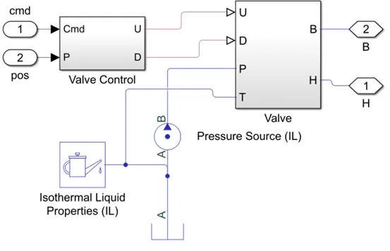
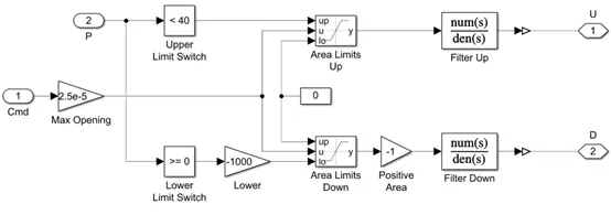
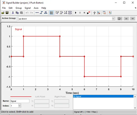
Valve Control-
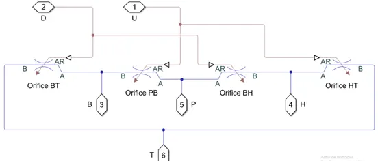
Valve-
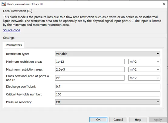
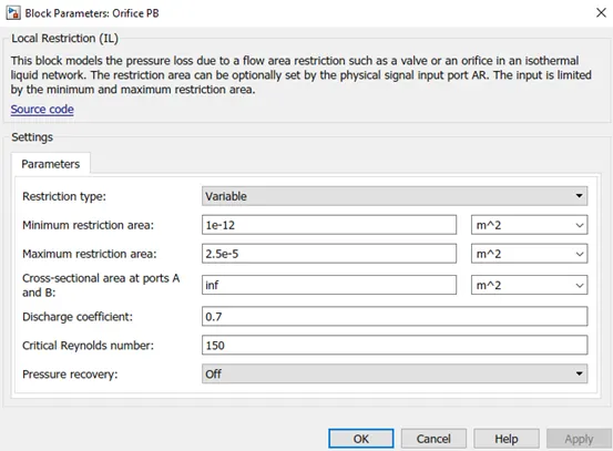
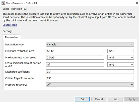
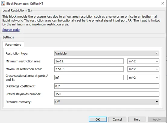
Iso thermal liquid properties-
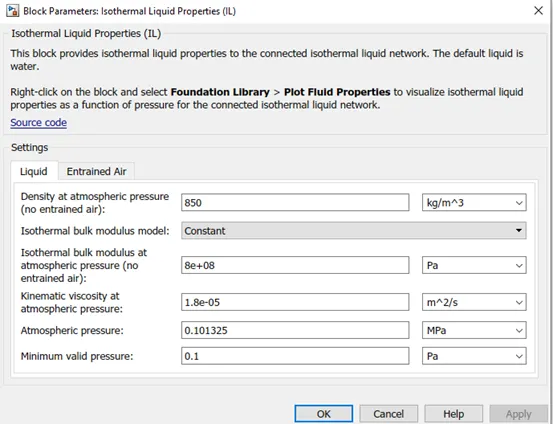
isothermal liquid domain, the working fluid is a mixture of liquid and a small amount of entrained air. Entrained air is the relative amount of non-dissolved gas trapped in the fluid. You can control the liquid and air properties separately: You can specify zero amount of entrained air.
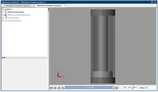
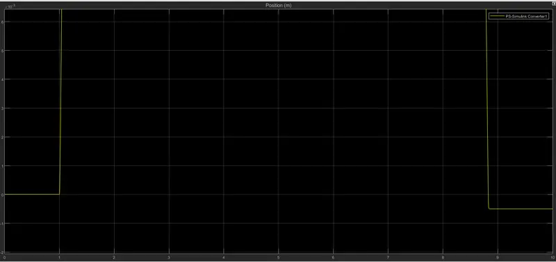
Conculation -The animation of the acutuator can be observed while running the Simulink file .