Speed Control of a Direct Current (DC) motor
DC Machines and its Construction
Any type of rotary electric motor that transforms direct current (DC) electrical energy into mechanical energy is referred to as a DC motor. The majority of kinds rely on the magnetic field's forces. Almost all types of DC motors feature an inbuilt device, either electromechanical or electronic, to sporadically shift the direction of the motor's current.
DC motors were the first commonly utilized type of motor because they could be driven by existing direct-current lighting power distribution networks. The speed of a direct current motor may be varied across a large range by varying the supply voltage or adjusting the current intensity in its field windings.
A basic direct current motor consists of a stator with a fixed set of magnets and an armature with one or more windings of insulated wire wound around a soft iron core that focuses the magnetic field. The windings often have numerous turns around the core, and in big motors, several parallel current channels might exist. The wire winding's ends are attached to a Commutator. The commutator energizes each armature coil in turn and links the spinning coils to the external power source through brushes.
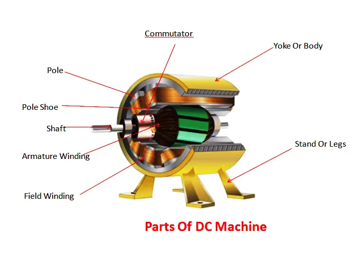
The structure of DC machine is mainly divided into two parts.
1.) Stationary Parts: -
2.) Rotating Parts: -
(1) Stationary Parts: -
The parts of the DC machine that remain stable even when the machine is running. This part of the machine is called the magnetic field system, which acts as the generator of the magnetic field and conductor of these magnetic fields. The following parts come under the magnetic field system. We will study all those parts in detail below.
Yoke
The outer hollow cylindrical cover of the DC machine is called a yoke, which completely covers the entire machine. The poles and inter-poles are installed on the yoke itself.
The yoke of a small size DC machine is made of cast iron, while in larger machines it is made of cast steel or rolled steel.
Following are the main functions of the yoke: -
- It acts as a mechanical base as it provides the basis for some parts of DC machine like poles and inter-poles etc.
- The yoke provides mechanical protection to the machine from dust, moisture and external injury.
- It acts as a good carrier for the magnetic fields generated in the machine.
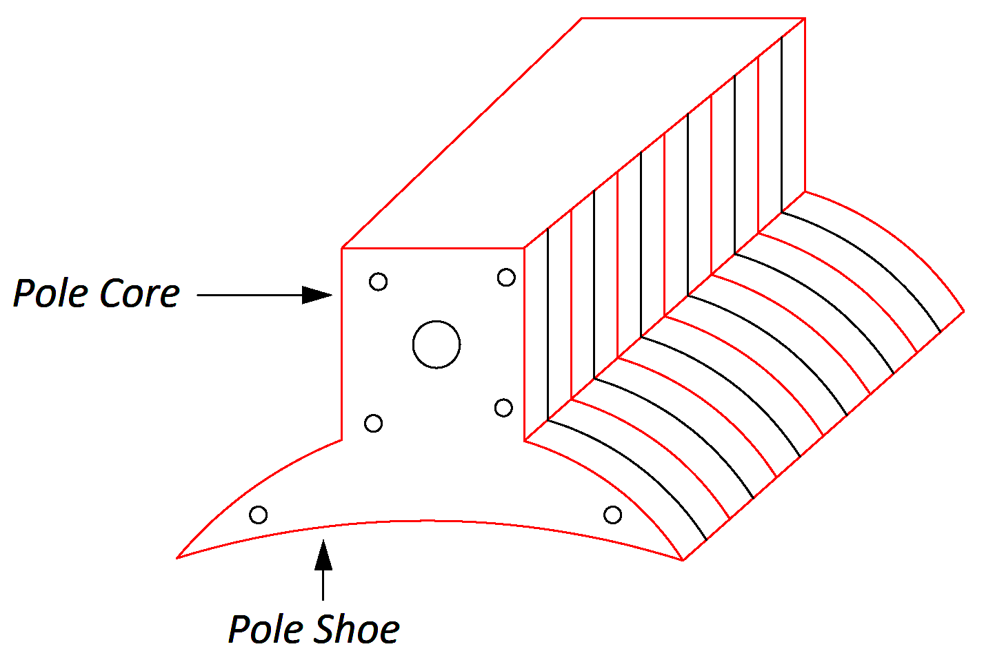
Pole & Pole core-
- In a DC machine, Pole is used to generate the main magnetic field.
- It is installed by welding on the yoke of the DC machine or with the help of a bolt.
- A pole is an electromagnet that is binding to produce a main magnetic field.
- To excite the electromagnet of the DC machine ie Pole is supplied from any external DC source such as battery etc., which causes the Pole to generate magnetic field.
- Pole is made of thin lamination's of silicon steel.
- To make the pole, use thinner lamination to reduce the power loss caused by eddy currents.
Pole shoes-
The surface in front of the pole of a DC machine is slightly bent, which is called the pole shoes.
- The area of its cross section is more than the area of pole.
- The main function of the pole pole is to keep the binding on the pole in its place and to evenly propagate the magnetic field generated by the pole on the armature.
Field winding-
The winding done at the pole of a DC machine to generate the main magnetic field is called field winding.
- When the field winding If an electric current is passed through an external DC source, it produces a magnetic field.
- The field winding of each poles are connected to each other in series in such a way that when supplied to them, their poles are sequentially forming the North Pole and South Pole.
- Commonly used copper conductors to do field winding on the pole.
(2) Rotating Parts: -
This is the part of the DC machine that starts rotating when the machine is powered on.
Armature-
An armature is the part of a DC machine that rotates in the magnetic fields generated by the machine's pole.
- It is cylindrical and is installed on the shaft of the machine.
- It is made by laminating circular discs of silicon steel.
- A lot of grooves are made on its periphery in which armature winding are installed.
- It has some air vents for cooling purposes.
Armature winding-
Armature winding is a place where mechanical energy is converted into electrical energy.
- It is installed in the grooves on the perimeter of the winding armature.
- The conductor used for this winding is normally copper.
- When the armature is rotated in a magnetic field by a primary conductor, the emf is induced in the armature winding.
Winding on armature is done in the following two ways-
- Lap winding
- Wave winding
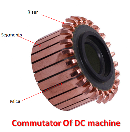
Commutator-
In a DC generator, the commutator converts the induced alternating current into a unidirectional current through the brush,
While the DC motor converts the commutator alternating force moment into a directional force moment. It is because of this property of commutator that it is called mechanical rectifier.
- It is cylindrical and rotates along the armature.
- The commutator is made of segments. These segments are insulated from each other by a layer of mica.
- The number of these segments is equal to the number of armature coils and an armature coil is attached to each segment through riser.
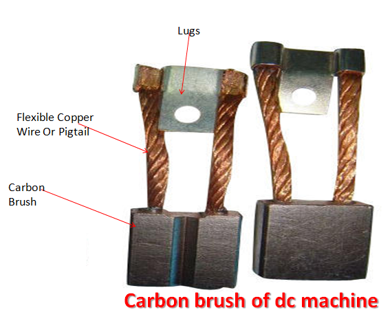
Brush-
The brush armature provides the external circuit by storing the electric current from the winding or the current from the external circuit.
Mathematical Model Of DC Machine.
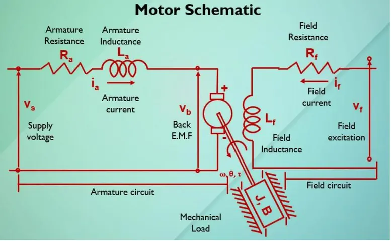
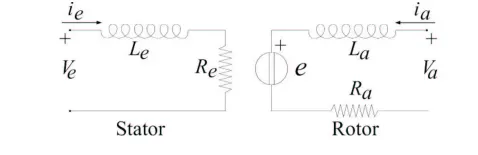
The motor schematic is shown below
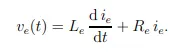
The stator of the motor will be assumed to have a single coil characterized by an inductance Le due to the windings and a resistance Re due to dispersions in the conductor. The equation associated with such an electric circuit is given by
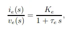
Since above equation is linear, by transforming in the Laplace domain the signals, it can be written as:

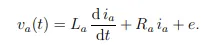
The rotor is assumed to be a single coil characterized by inductance La and resistance Ra, but it has to be taken into account the back EMF of the motor. The equation associated with such an electric circuit is given by
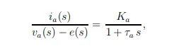
Again, since relation (16) is linear, by transforming in the Laplace domain the signals, it can be written as:
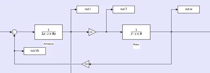
The Electrical equivalent of electrical circuit is shown below:
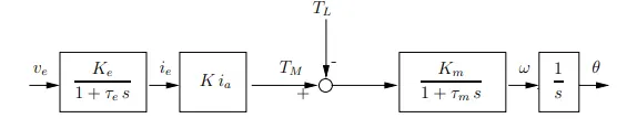
The Two Transfer functions are cascaded to one another. This completes the transfer function modeling of the DC machine. The Block diagram of the DC motor is shown below:
In This challenge, we going to discuss the method of speed controlling of DC motor using a PID Controller.
Step 1: Make a Simulink Transfer function model of a DC motor Using the following parameters:
1. Torque proportionality constant (Kt) = 0.01
2. EMF proportionality constant (Km) = 0.01
3. Friction Coefficient of load and motor (B) = 0.1
4. Moment of inertia of motor and load (J)= 0.01
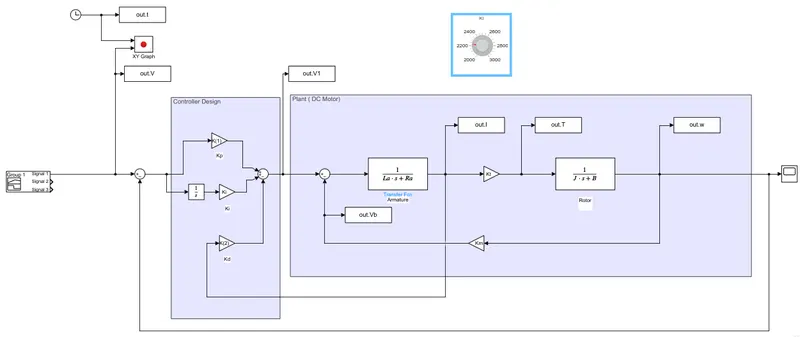
Step 2: The next step is designing the PID controller for that we need to find the Kp and Kd gains.
Step 2(1): System parameters are assumed like frequency and damping coefficient. Then Find the poles for a second order transfer function. Here the frequency of 1 Hz and Damping coefficient of 0.5 is considered.
Step 2(2): After finding poles find out the A and B matrix at the initial condition. Then Find the Kp and Kd gains using the 'place' command.
The Ki value is tuned according to the response we need i.e. minimized overshoot and settling time.
A tuning knob is attached to the Ki values in order to minimize the steady state error, Overshoot, and settling time.
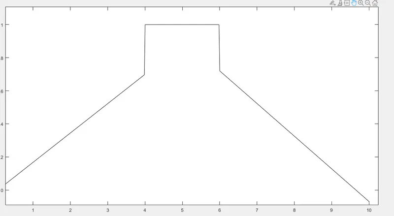
A Test Signal is created which replicates Acceleration, constant velocity, and Deceleration. The Signal is attached as the voltage source.
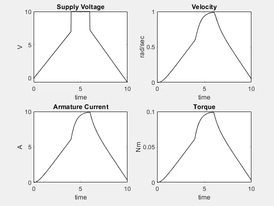
The Response of the motor without a controller is as shown below:
The Response shows a delayed response that doesn't follow the supply voltage. So, it is not an ideal condition. In order to match the velocity response with the reference signal i.e. voltage, we need to implement the controller designed in the above steps.
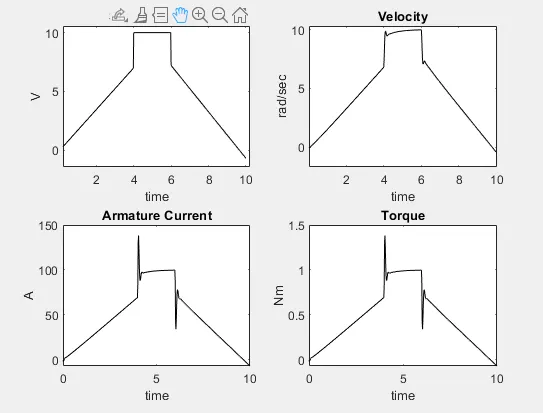
With the implementation of the Controller the response is described below:
The figure shows a better response while adding the controller. Through the Armature current and torque, a large over-shoot can be seen but the aim of the controller was to make the speed follow the reference which is attained by the controller. The over-shoot of the current and torque can be minimized by using another PID controller.