Project - Speed Control of a Direct Current (DC) motor
THE SCHEMATIC DIAGRAM OF THE DC MOTOR
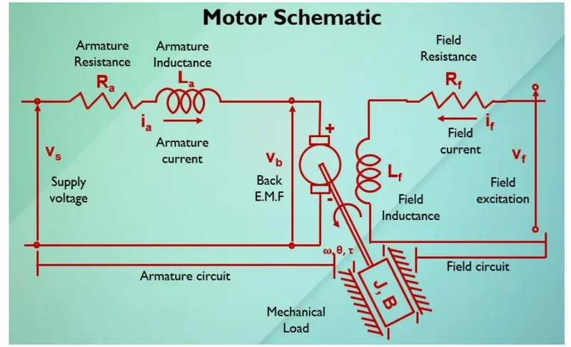
A DC motor is any of a class of rotary electrical motors that converts direct current (DC) electrical energy into mechanical energy . A simple DC motor has a stationary set of magnets in the stator and an armature with one or more windings of insulated wire wrapped around a soft iron core that concentrates the magnetic fieldThe ends of the wire winding are connected to a commutator , The commutator allows each armature coil to be energized in turn and connects the rotating coils with the external power supply through brushes.
i.) Mathematical modelling from the first principle
Kirchhoff’s voltage law
Vf = Rf*If + If *d(if)/dt
Vs=Ra*Ia + La*d(Ia)/dt + Vb
The algebraic sum of all voltage around any closed loop in a circuit is equal to zero.
The relation between the Back EMF, angular velocity & Torque are related by
Vb =Km*d(theta)/dt. Vb= Back EMF; Km = Back EMF constant;d(theta)/dt = angular velocity
T = Kt*Ia. T = torque; Kt = Torque constant
The open loop transfer function for the motor with the speed(w) & Supply Voltage (Vs) can be derived as
w(s)/Vs(s) = Kt / [(J *La *s^2) + (J*Ra+b*La) *s+ (b*Ra+Kt*Km)]
A proportional integral & derivative (PID) controller design is to obtain the desired angular speed using the
appropriate Supply voltage.
Vs = Supply Voltage b = motor viscous constant.
Ra = Armature Resistance Ia = Armature Current; La = Armature Inductance
Vs -Vb = Ra*Ia + La*d(Ia)/dt ---------(1)
J*d^2(theta)/dt + b*d(theta)/dt = Kt*Ia -------(2)
Modelling an Electrical Engineering system using MATLAB code:
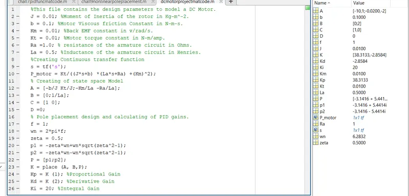
simulink modeling through equation
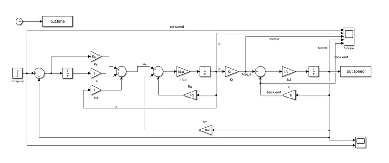
simulink modeling through transfer function
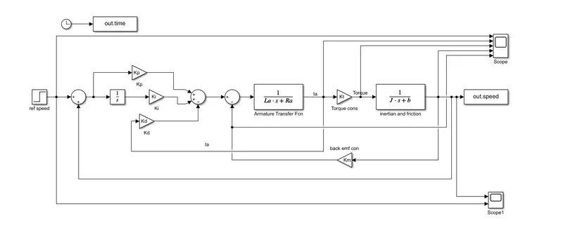
We are taking the value of zeta as 0.5 and hence the value of Kp=38.313, Kd=-2.85 and Ki= 20
THE RESULTS OBTAINED ARE AS FOLLOWS
Scope of the refference signal and speed
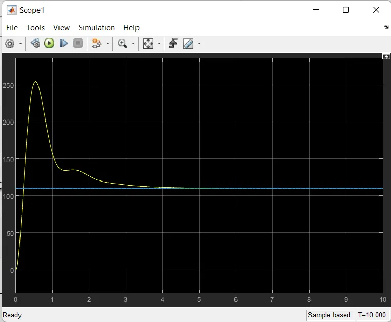
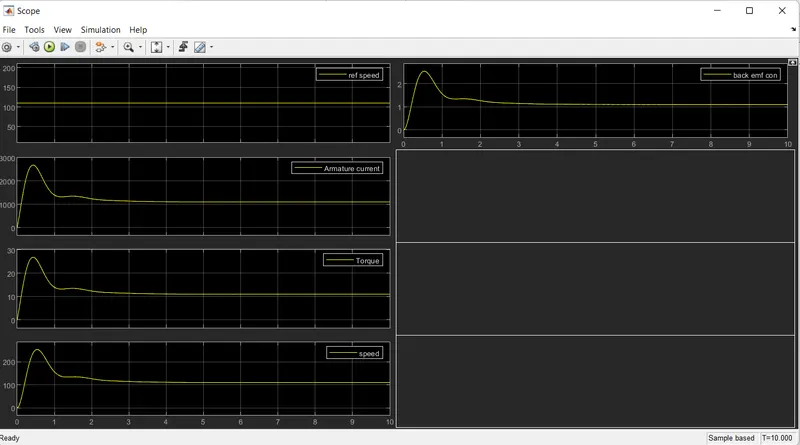
To make best performance we have to get by minimizing the overshoot and less settling time with the values of i)settling time < 2sec; ii)over shoot <5%; iii) steady state error <1% .These can be obtained by tunning the values of Kp,Kd,Ki accordingly By an analysis , increasing the value of Ki will largely help in obtaining the prefect condition
so we give the value of Kp= 20; Kd=-1.2 ; Ki=30 , here are results
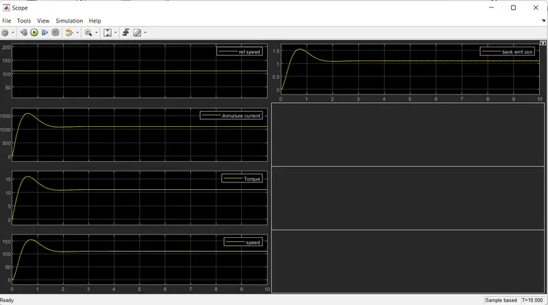
checked with more values of change in gains
Kp=35 ; Kd=2 ; Ki=50 the result as follows
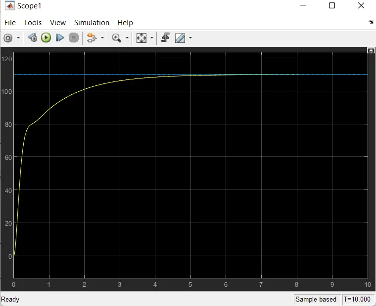
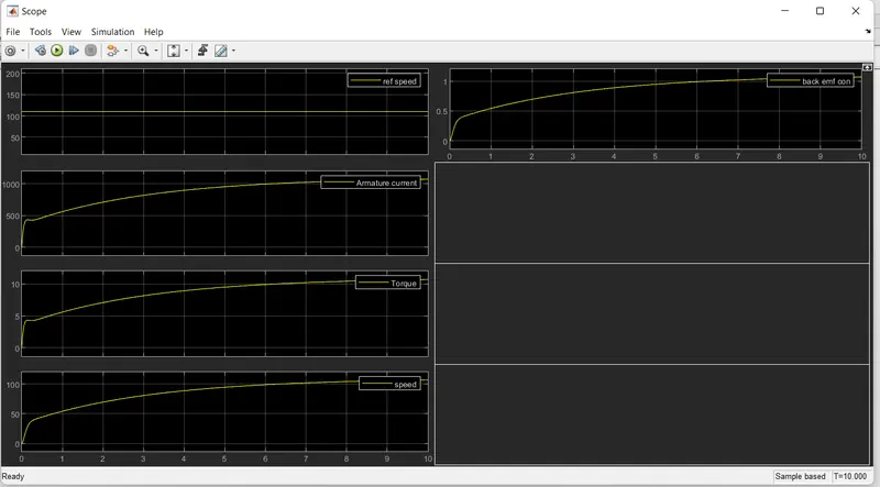
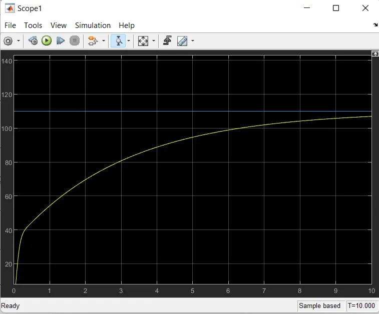
Kp=50; Kd=10 ; Ki=50 the result as follows
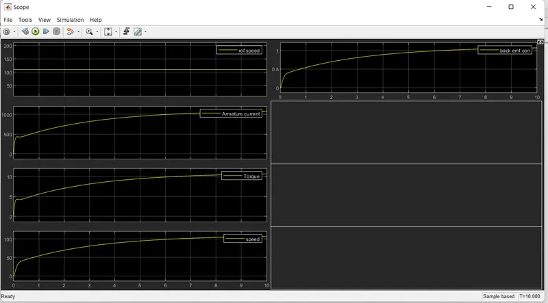
Kp=100 ; Kd=1; Ki=300 the result as follows
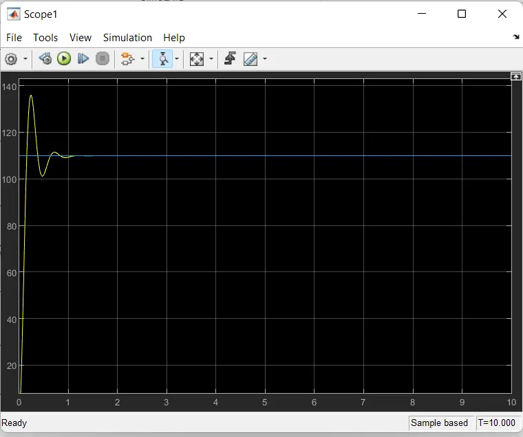
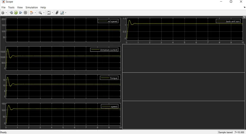
we use Kp to increase the speed of response,use Kd to reduce the oscillation,use Ki
to increase the speed with which the steady-state error is driven to zero.
CONCLUSION
We have discussed about DC motor working Principle and Mathematical modelling and created MATLAB
Script to Modelling of electrical engineering System. Using MATLAB, we have calculated PID gain values
for Under damping system. Using these values also developed Simulink model with PID gains. Verified the
Simulink model for different PID (proportional, Integral& Derivative) Gain values. By observing the results,
we can say proportional gain is increase the speed of response, Derivative gain reduce the
oscillations and increase the stability of the system & Integral gain reduce the steady-state error of
system.