Project 1
Develop a double-acting actuator model using Simscape Multibody and Simscape components. The mechanical system of the cylinder needs to be built using Simscape Multibody library components / blocks, and the hydraulic system needs to be modelled using Simscape library physical components.
MODELLING OF A DOUBLE ACTUATING PISTON MODEL
Simscape Multibody models the mechanical system of the cylinder, and Simscape models the hydraulic system. You can use Translational Multibody Interface block to connect the two systems.This example shows how to model a double-acting actuator with Simscape Multibody and Simscape
Here we can model a pistion cylinder arrangment of half-retracted, fully retracted, and fully extended.
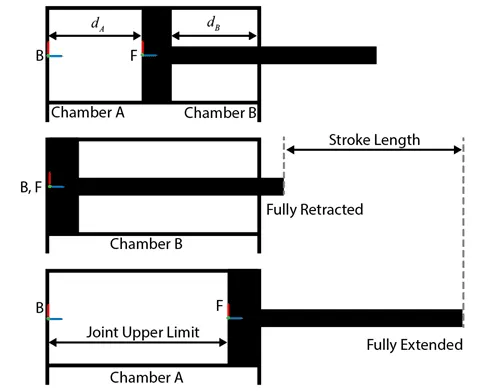
A double-acting hydraulic cylinder that causes the piston to contract and return the piston to its original position when high pressure hydraulic fluid is pumped to the upper port. This can be done quickly or very slowly, with precise control as needed.
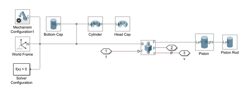
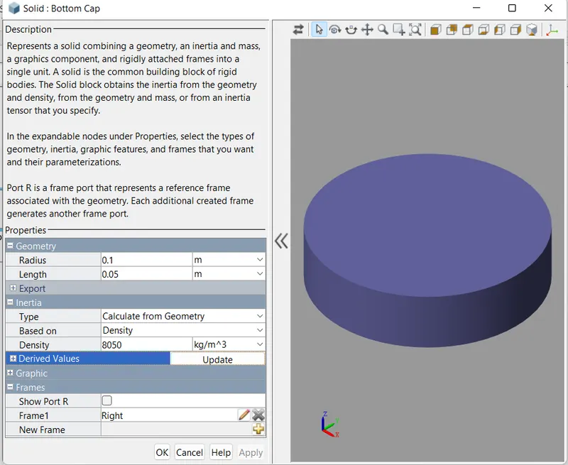
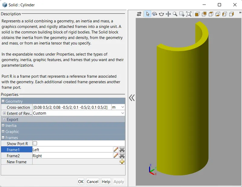
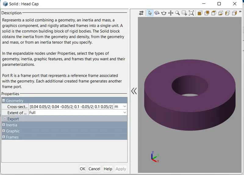
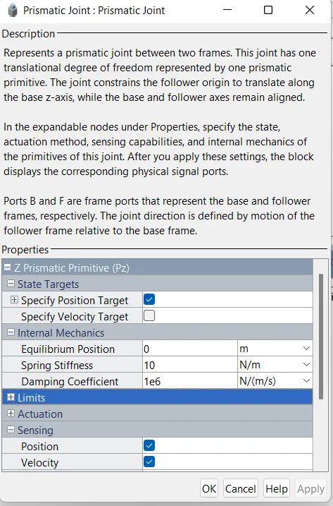
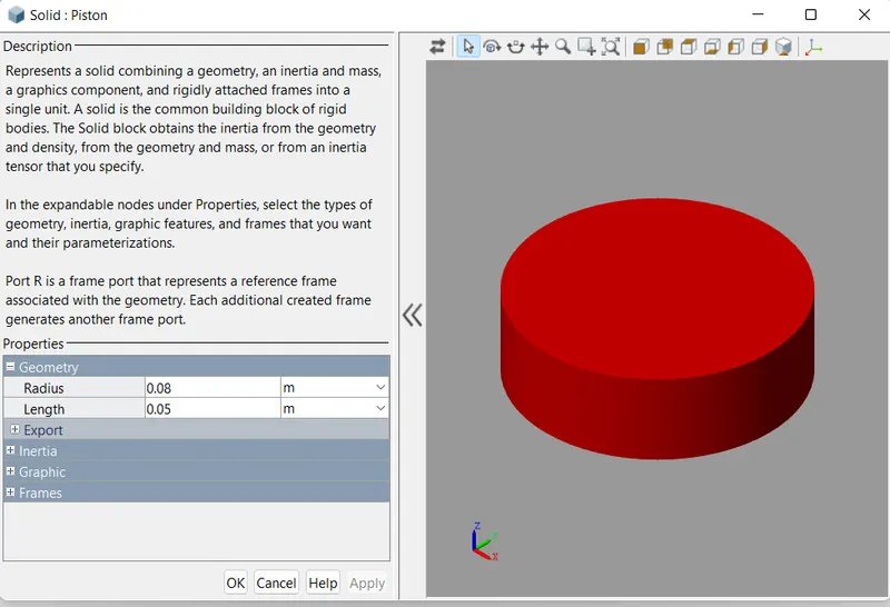
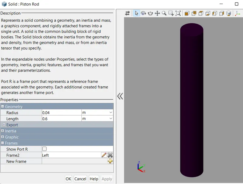
We can model the mechanical part of the system in Simscape Multibody. modeling the cylinder and piston, we can use the Revolved Solid (Simscape Multibody) & Cylindrical Solid (Simscape Multibody) blocks. To provide the translational degree of freedom for the piston, Use a Prismatic Joint (Simscape Multibody) block. To easily calculate the lengths of the chambers A and B, you can attach the base frame (B) and follower frame (F) of the joint to the centres of the left inner surface of the chamber A and the left surface of the piston respectively. Here the Z axis of the B and F frames are aligned and both point toward chamber B.
Using this convention, the length of the chamber A, dA, is the position output of the joint block, and the length of the chamber B, dB, equals the difference of the stroke length and dA. To ensure that the piston does not travel beyond the ends of the cylinder, you can specify the upper and lower position limits of the Prismatic Joint block.
The corresponding simscape model are shown below
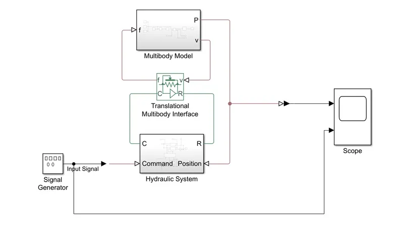
In above model the hydraulic system and multibody model is connected by translational multibody interface block. This block is an interface between a Simscape Multibody joint and a Simscape mechanical translational network. Ports R and C are mechanical translational conserving ports that connect to the two nodes in the mechanical translational network which share the same force and relative velocity as a primitive in the Multibody joint. Ports v and f are physical signal ports that connect to the Multibody joint. Input port v accepts the relative velocity sensing output from the joint primitive. Output port f provides the force actuation input to the joint primitive.
THE MULTIBODY REPRESENTATION OF THE OF THE DOUBLE ACTUATING PISTON MODEL
THE HYDRAULIC SYSTEM REPRESENTATION OF THE OF THE DOUBLE ACTUATING PISTON MODEL
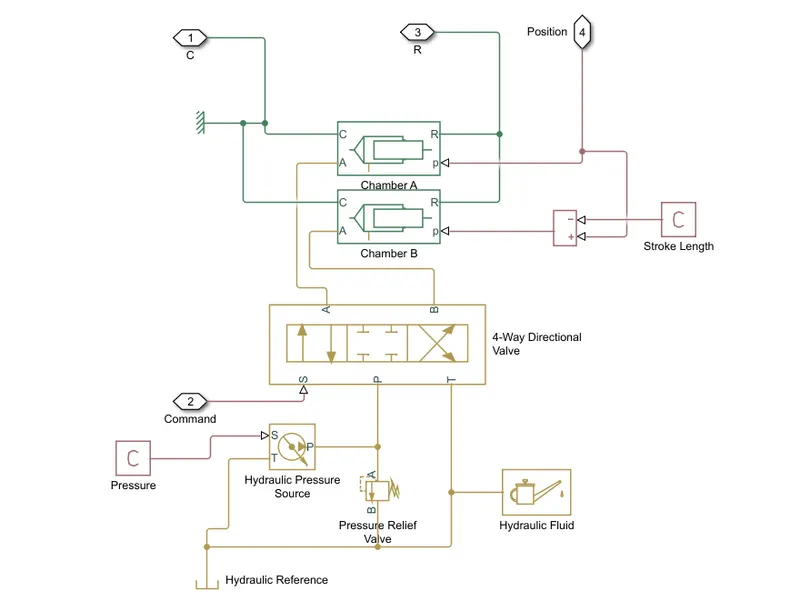
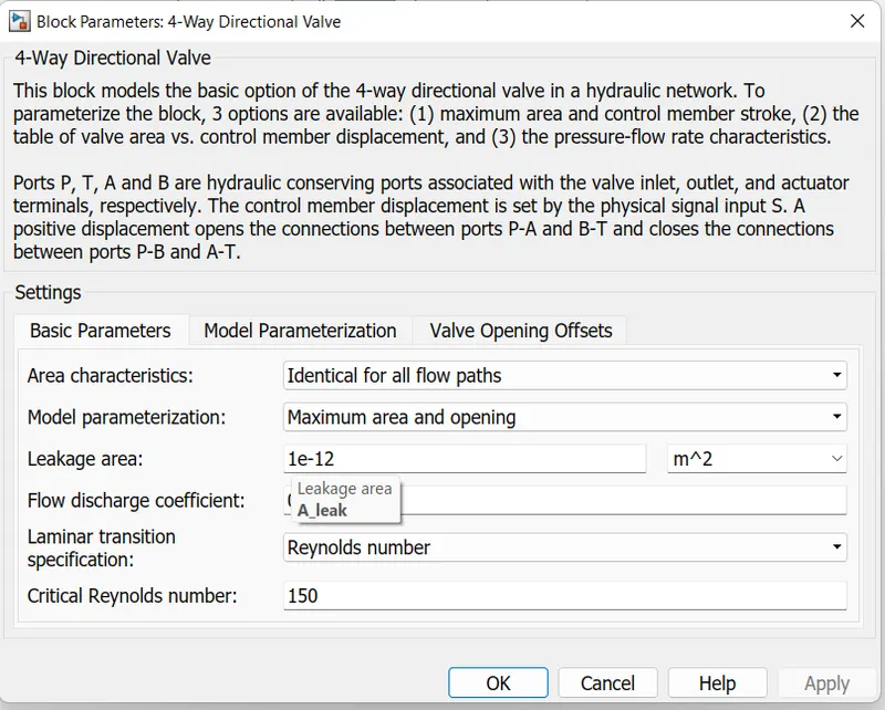
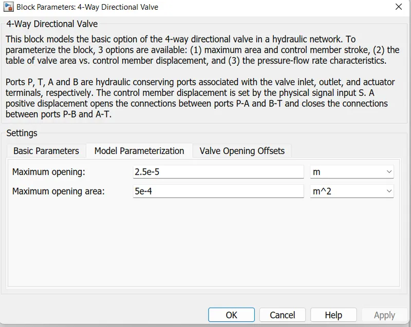
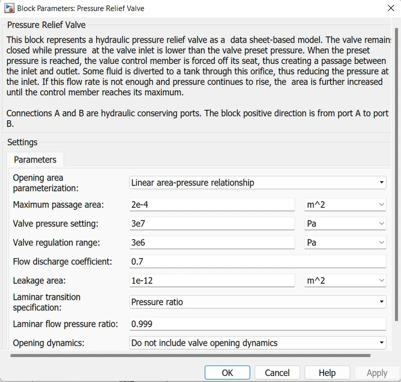
In the model a 4-way directional valve is used , pneumatic components for directional control. By providing four distinct flow paths, these valves make it easy to reverse the motion of a cylinder or motor. Also a Pressure relief valves is designed to open at a pre-set pressure and discharge fluid until pressure drops to acceptable levels.
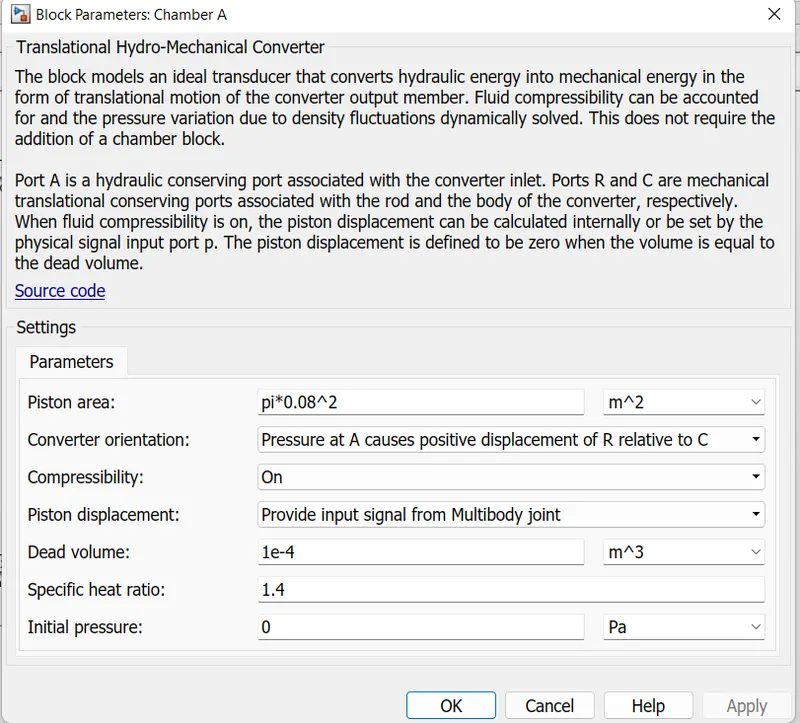
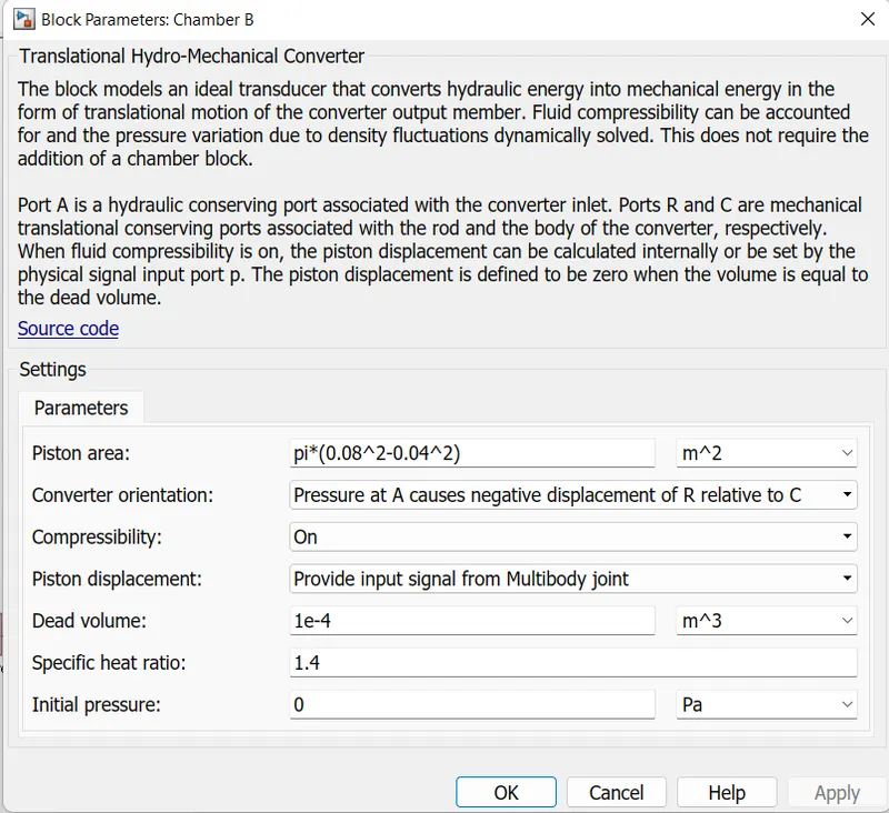
The Translational Hydro-Mechanical Converter block (Chamber A or B) models are an ideal transducer that converts hydraulic energy into mechanical energy, in the form of translational motion of the converter output member, and vice versa. The compressibility option makes the converter account for dynamic variations of the fluid density.
A hydraulic fluid or hydraulic liquid is the medium by which power is transferred in hydraulic machinery.
CHAMBER A IS USED FOR FORWARD DISPLACEMENT OF THE PISTON
CHAMBER B IS USED FOR REVERSE DISPLACEMENT OF THE PISTON
PRESSURE RELIEF VALVE
HYDRAULIC FLUID
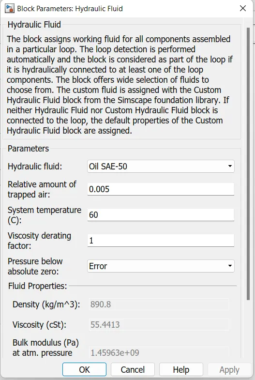
The Hydraulic Pressure Source block represents an ideal source of hydraulic energy that is powerful enough to maintain specified pressure at its outlet regardless of the flow rate consumed by the system.
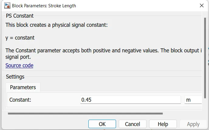
The two constant blocks are used in the above model, one is for supply pressure & second one indicates stroke length.

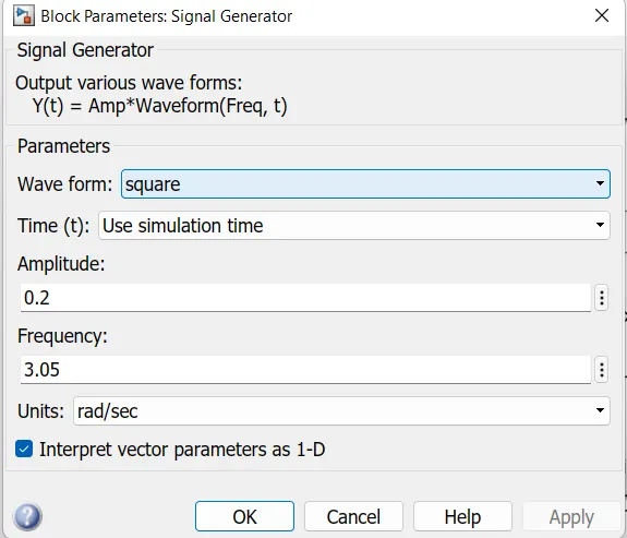
Input is given in the order of signal generator
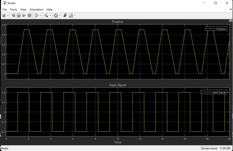
The Results are as follows:
The stop time is set to be 20 sec , scope output and stimulations are shown
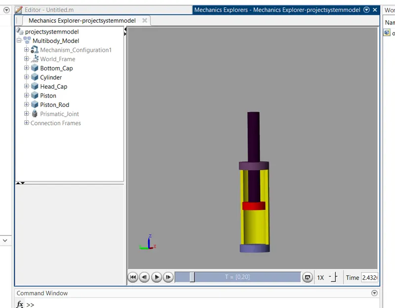
The mechanisms block looks as follows and cylinder customized to show the inner mechanism.