Project - Speed Control of a Direct Current (DC) motor
PROJECT: DC MOTOR SPEED CONTROL USING PID CONTORLLER
Aim: To design a Simulink model for the DC motor shown in Figure 1. amd aslo by Using the Proportional, Integral, and Derivative (PID) control design knowledge gained in the training to design, develop and test a controller to maintain a desired speed for the motor.
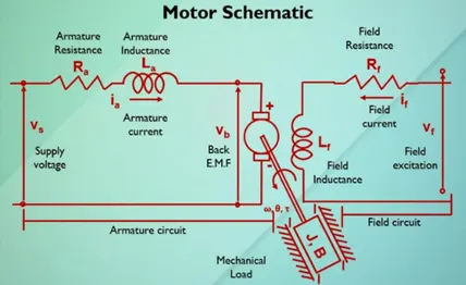
Figure 1
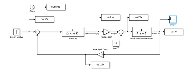
Designed above DC motor modelling in MATLAB Simulink tool by considering below parameters.
J=2.4; %moment of inertia of the rotor kg-m^2
B=0.5; %Motor viscuss frection constant in N-m-s
Km=10; %Back EMF constant v/rad/s
Kt=1; %Notor torque constant N-m/amp
Ra=1.0; %Resistance of the armature ckt in ohms
La=0.5; %Inductance of the armature ckt in H
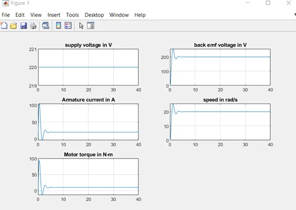
subplot(321);plot(out.time,out.Vs);grid; title('supply voltage in V');
subplot(322);plot(out.time,out.Vb);grid; title('back emf voltage in V');
subplot(323);plot(out.time,out.Ia);grid; title('Armature current in A');
subplot(324);plot(out.time,out.w);grid; title('speed in rad/s');
subplot(325);plot(out.time,out.Ta);grid; title('Motor torque in N-m');
DC motor Simulink model:
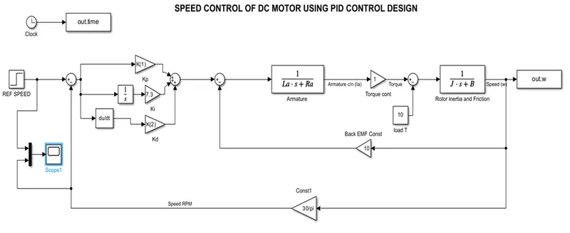
DC motor Simulink model using PID controller:
Above DC Motor model tuned by designing the PID control by designing the below Kp, Kd &Ki values using pole placement method & analysed model output speed for various speed as a reference input.
Matlab script:
%This file contains Design parameters of DC Motor Parameters.
J=2.4; %moment of inertia of the rotor kg-m^2
B=0.5; %Motor viscuss frection constant in N-m-s
Km=10; %Back EMF constant v/rad/s
Kt=1; %Notor torque constant N-m/amp
Ra=1.0; %Resistance of the armature ckt in ohms
La=0.5; %Inductance of the armature ckt in H
A=[-B/J Kt/J;-Km/La -Ra/La ];
B1=[0;1/La];
fn=1;
wn=2*pi*fn
zeta=0.94
p1=-zeta*wn+wn*sqrt(zeta^2-1)
p2=-zeta*wn-wn*sqrt(zeta^2-1)
p=[p1;p2]
K=place(A,B1,p)
Ki=7.3
K =34.4731 4.8020
Kp=34.4731
Kd=4.8020
Reference input Speed 1500 rpm
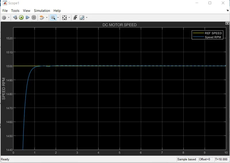
Reference input Speed 1500 rpm
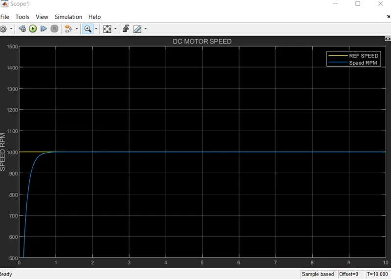
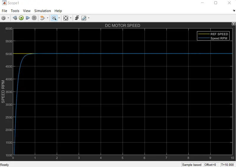
Reference input Speed 5000 rpm
Conclusion:
we have designed In this project a Simulink model for the DC motor as shown in Figure 1.and also we Use the Proportional Integral and Derivative PID control design knowledge gained in the training to design develop and test a controller to maintain a desired speed for the motor