Speed Control of a Direct Current (DC) motor
AIM:
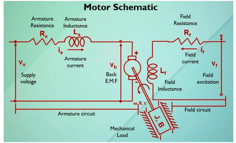
In this project, a Simulink model for the DC motor will be first developed per the schematic shown in Figure 1.
The Proportional, Integral, and Derivative (PID) control design knowledge gained in the training wiil be used to design, develop and test a controller to maintain a desired speed for the motor.
Key Highlights:
- Mathematical modeling from the first principles
- Modeling an Electrical Engineering system
- Simulink based modeling
- Control law design and test
- Stability of a dynamic system
The mathematical model of DC motor is shown below
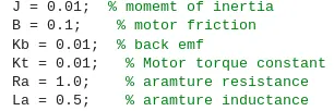
This model is implemented in Simulink with parameters
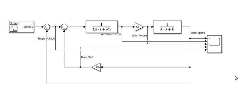
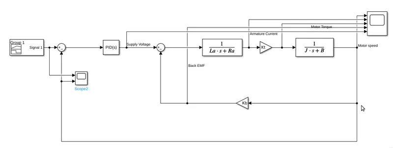
Simulink block diagram is as shown below
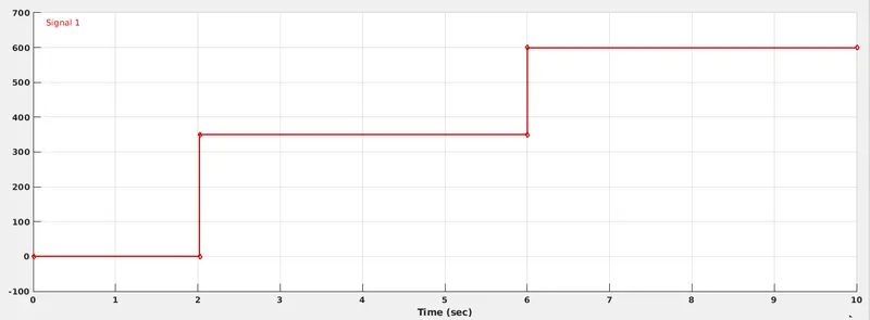
A step waveform of the shape which is shown below is given as speed reference for the motor
The output of motor is as shown below
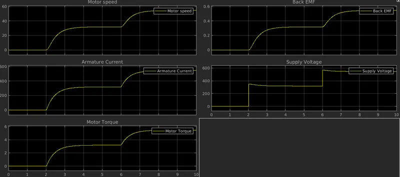
We can clearly see that motor is not tracking the commanded speed. So we intoduce a PID controller for tracking speed as shown below
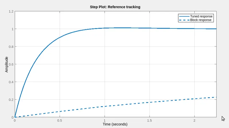
The PID controllers is tuned using control systems toolbox.
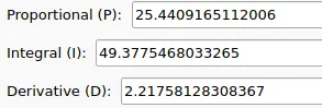
PID values obtained after tuning are
The output for this tuned motor is obtained as
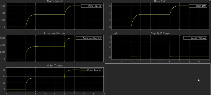
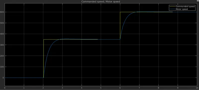
Figure below clearly illustrates how motor is tracking the commanded speed
Conclusion:
We can see that inherently motor has tracking capability but it's limited only for a finite range. A PID control can be used effectively to control and track motor speed.
Both the motors are build in the same simuink file and attached for reference.