Project - Position control of mass spring damper system
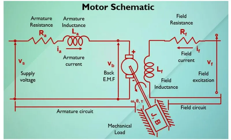
In this project, a Simulink model for the DC motor will be first developed per the schematic shown in Figure 1.
Use the Proportional, Integral, and Derivative (PID) control design knowledge gained in the training to design, develop and test a controller to maintain a desired speed for the motor.
Answer:-
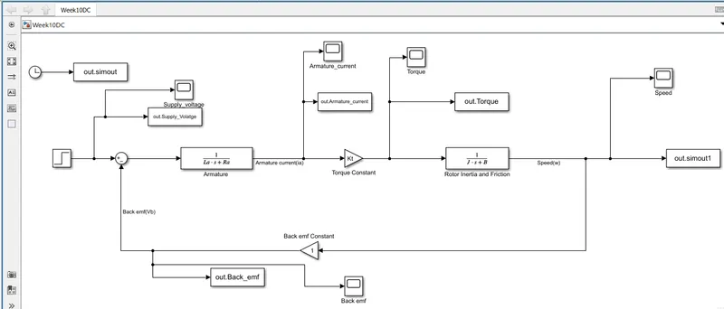
- a Simulink model for the DC motor developed per the schematic shown in Figure 1.
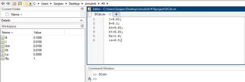
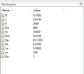
- Data used in respective DC motor:-
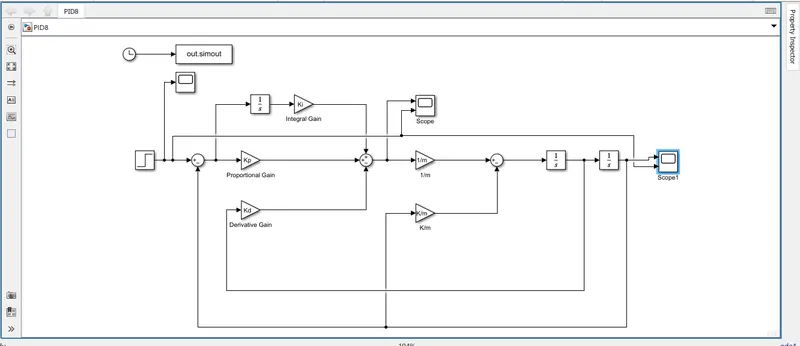
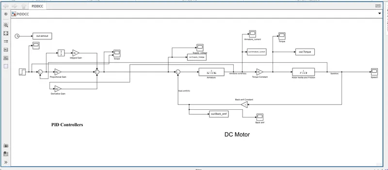
- Simulink model of a PID controller.
- Graph of PID:
As per Question,Select the P, I and D gains such that the control design knowledge gained in the training to design, develop and test a controller to maintain a desired speed for the motor.
So, I Select the data as follows:
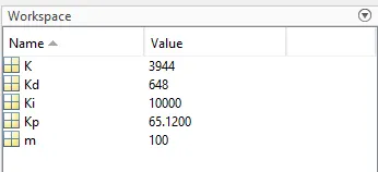
and we get the output as following.
- Simulink Model of a PID controller to regulate the speed of the DC Motor
and respective Data are:-
Now ,let's see speed of motor change as per suppy of PID controller
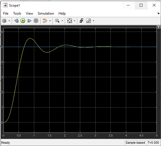
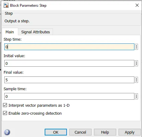
i)Here we supply ,step time "0" and final Value "5".
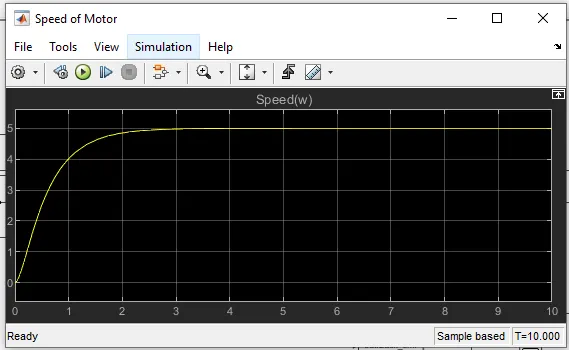
We got the speed of motor as follows:
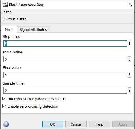
ii)Again we supply step time "5" and final Value "5".
We got the Speed of motor as follows:
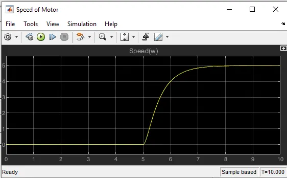
- So, here we can see our value or speed of motor change as per reference signal of PID controller.
- Now, as in (i) condition, step time "0" and final value is 5, so we can see the graph, the speed of motor from initially (i.e 0 sec) started rising and ultimatially reached the speed of 5 and get stable.
- And In (ii) condition, step time "5"and final value is also 5, so we can see in the graph, the speed of motor for first 5 sec is 0, and after that it started rising and achieve the speed of 5
- So we can say that the speed of motor varies with respect to reference signal.