Week -2
Blocks used
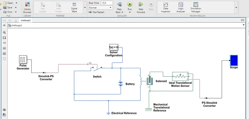
1.Pulse Generator:
The pulse generator blocks generates "square wave pulse" at regular intervals .The block waveform parameter Amplitude,pulse width periods and phase delay ,determine the shape of the output waveforms.
2. Simulink P S converator:
These blocks converts the simulink input signal in to the physical signal.
3. Switch:
The blocks represents a switch controlled by an external physical signal . when Physical signal greather than the thersold value then the switch is closed , otherwise switch is open.
4.Battery:
It provides the voltage to system.
5.solenoid:
These blocks shows the position of the plunger with respect to the 'EMF' induced which depends on the intial position of the plunger . The spring constant is set to '0'.
6.Mechanical and electrical reference:
These provides the references point to the signal.
7. Ideal translation motion sensor:
The block represents an ideal mechanical translational motion sensor that is device that convert an acorss variable measured between two mechanical translational nodes in to a control signal proportional to velocity & postion.
8. Scope:
To view to the characterictics of a property with respect to time{simulink time}.
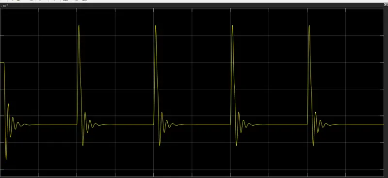
OUTPUT OF SCOPE:
simulink model of door bell:
Result:
- This is result obtained by for a time period for 10 sec of the given simulation.
- For every interval of '2' sec the switch is turned ON &OFF , hence such waveform is obtained .
- Damping effect is observed beacause of the damping parameter which set in solenoid block of 1N (m\s).
2. Use a thermistor to sense the temperature of a heater & turn on or turn off the fan
simulink model:
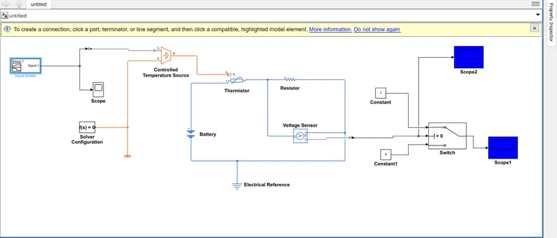
- In above model consist of thermister,resistor, voltage sensor, referencees, controlled temp sensors, battery , scope, signal builder, switch , etcc.
- Signal builder is used as input order to to acheive the condition . input from signal builder supplies to temp controlled source which is connected to temperature sensor, temperature source is connected to thermister.
- Thermister is used to sense the change in resisor value which inturn change in temperature . A Thermister is a type of resisor whose resistance depends on temperature , more so than in standard resistor.
- voltage sensor is used to which controlls the fan by sensing thersold value,Intially for 295k we need to get the thersold value and keep it as standard and apply to the switch condtion which measures the value in every change in temp.
output:
FIGURE 1:
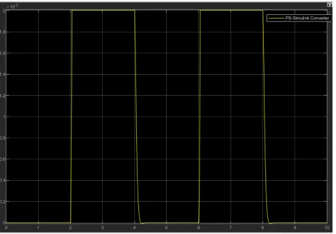
FIGURE 2:
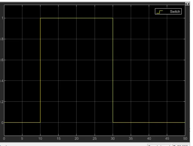
FIGURE 3:
conclusion:
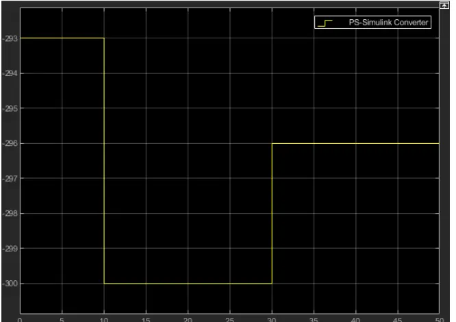
The fan is controlled by using thermister which is shown in fig 1 . The temperature changes also obtained in graph by using temperature sensors as shown in figure 3 . in fig 2 the switch is off for 0-10 sec and ON for 10-30 sec.