Week - 4
Task-1:
Objective:
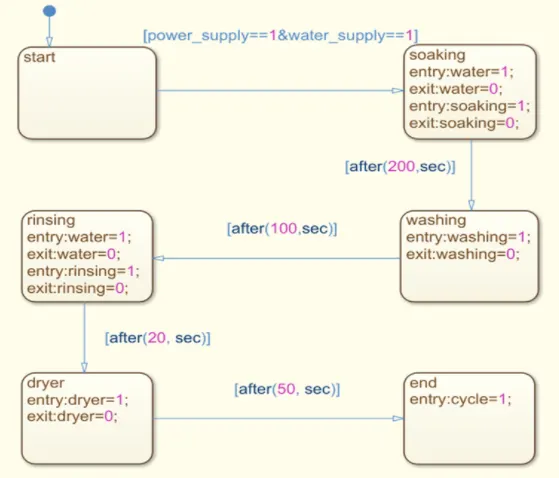
1. To implement the control logic of a washing machine using stateflow as per given sequence:
.) if the power supply is avaiable , the system gets activated.
.) if the water supply is available , stop the process and indicate through LED.
.) soaking time should be 200s follwed by washing time of 100s.
.) then rinsing happens for next 20s and dryer runs for 50s.
after all the processes have compeleted turn on the finished LED
CONTROL LOGIC:.
EXPLANATION:
(Note: here we are considering that we have continuoes power and water supply . we can't cut off power supply when simulation is running . The system operates only in given conditions)
1. In the above control logic block diagram starting state is created with two transition conditions, 1st is power supply =1 and 2nd is water supply =1.That means both water and power supply are on
2. The second state is soaking , in his state the water suplly is required so we give the water supply. after compeletion soaking and water suplly are off As per given condtions we gave a time 200 sec for this process with the help of transition condtions.
3. The third state is washing, in this state only washing is done with alredy avaiable water in washing machine this process is took 100 sec time per given transition condtions. and water drains from the machines.
4. The fourth state is rainsing , in this process repeated washing has happened so we required water supply here.. The water supply is off after 20 sec and rinising state also done as per given transition conditions.
5. (NOTE:we are using water supply in rininsing which is not mentioned in condition)
6. The fifth state is dryer , in this process the cloths are dry in 50 sec as per given condition after compeletion of process dryer would off with the help of state condtion.
PARAMETER SYMBOLS:
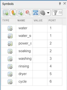
1. INPUT DATA: water supply , power supply
2. OUTPUT DATA: water, soaking , washing, rinising, dryer, cycle.
MODEL
WASHING MACHINE MODEL:
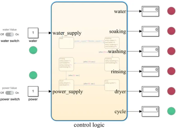
1.In this model we use stateflow chart to create control logic for washing machines. we used to two switches to opertes power and water supply.
2. Lamps are used to watch power and water supply state which is on or off . The switch and lamp are connected to constant block . constant block connected to with the control logic.
3. All process ports are connected with display and display is connected with lamp to watch the process of washing machine with respect to given time.
4. After completion of all process cycle light would appear green. we run this simulation for 400 sec.
RESULTS: To see the result of above the images to the model with challenge.
CONCLUSION:
We can conclude that we simulate the washing machine control logic with the help of stateflow and got satisfactory results.
AIM:
Make a simulink chart for "gear shift" logic with the given condition.
CONTROL LOGIC:
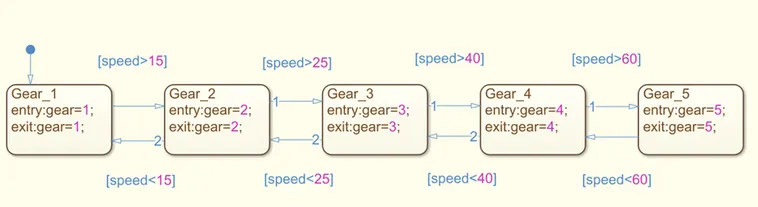
As per given condition for gear shifting , we created stateflow diagram with help transition to given condition with respect speed.
PARAMETER SYMBOLS:
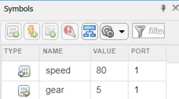
1. INPUT DATA: Speed
2. OUTPUT DATA:Gear
MODEL:
GEAR SHIFTING MODEL:
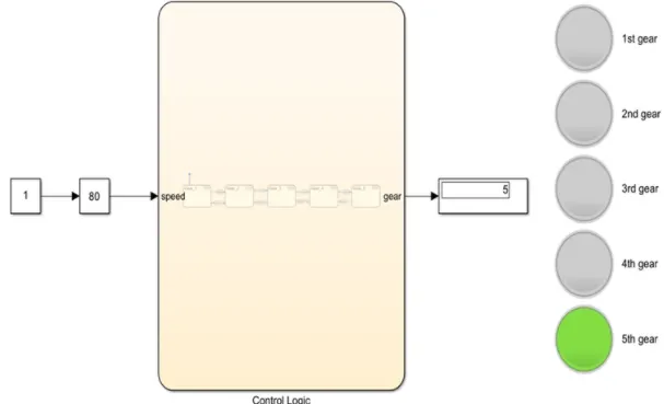
In the above model we used slider gain block for variable speed and connected to control logic stateflow block.Display block is connected to control logic to see which gear is running and also used to lamp for better graphical presentation to user.
RESULTS:To see the result of above the images to the model with challenge.
CONCLUSION:
We can conclude that we simulate the gear shifting control logic with the help of stateflow and got satisfactory results.