Project - Position control of mass spring damper system
Project on Position Control Of Spring-Mass-Damper system.
Objective:
- Obtain the transfer function of a mass spring damper system and use it in the model.
- Add a PID controller to adjust the force on mass so that its position follows the given reference signal.
Given data:
- Mass(m)= 3.6 kg
- Spring Constant (k)= 400 N/m
- Damping Coefficient (c)=100 Ns/m
- Reference Input signal.
Transfer function:
- The transfer function is defined as the ratio of the Laplace transform of the output variable to the Laplace transform of the input variable assuming all initial conditions to be zero.
Spring-Mass-Damper System:
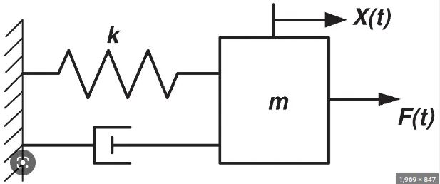
According to Newton's Law:
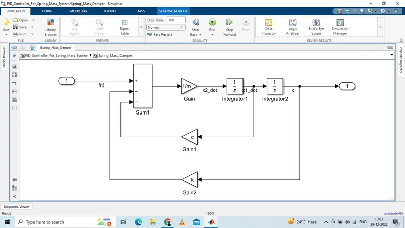
m*(d^2/dt^2)(x)+c(d/dt)x+kx= F(t)
Taking Laplace transform
m(s^2)x(s)+csx(s)+kx(s)=F(S)
The transfer function of the spring-mass-damper system is given by
x(s)/F(s)=[1/(ms^2)+cs+k]
Simulink Model:
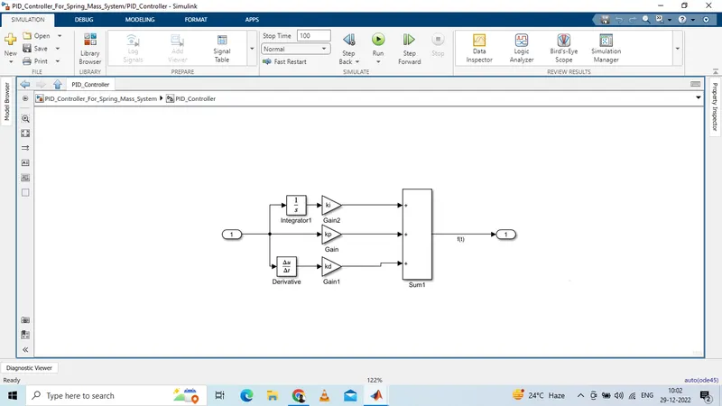
%Parameters of PID Controller for spring mass damper system
% Given data
m=3.6;% Mass
k=400;% Spring Constant
c=100;% Damping coefficient
% Design Parameters
wn= sqrt(k/m);
zeta= c/(2*wn*m);
A=[0 1;-k/m -c/m];
B=[0;1/m];
% Pole Placement
p1= -zeta*wn+(wn*sqrt(zeta^2-1));
p2= -zeta*wn-(wn*sqrt(zeta^2-1));
P=[p1;p2];
K= place(A,B,P);
kp=K(1);
kd=K(2);
ki=200;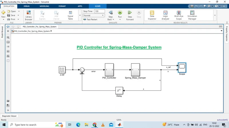
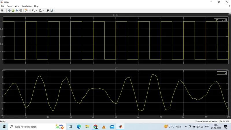
Scope Output:
Blocks Used:
Pulse Generator: To provide the input reference signal.
Scope: To display the output.
Sum: To add input signal
Gain: To multiply a gain by the input signal
Integrator: To integrate the input signal
Differentiator: To differentiate the input signal
Delay: To provide a delay to the input signal
Conclusion:
The above model shown is a PID controller for the spring-mass-damper dynamic system. By using the pole placement method we have calculated the kp and kd gain values and for ki the values are carried according to the desired response. From the scope output, it is clear that with the help of the PID controller we can able to control and reduce the error between the reference input to the desired output.