Week -2
1)
Aim- Design, and implementation of Simulink model of a doorbell system using a solenoid block.
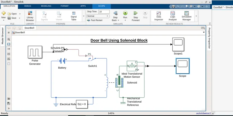
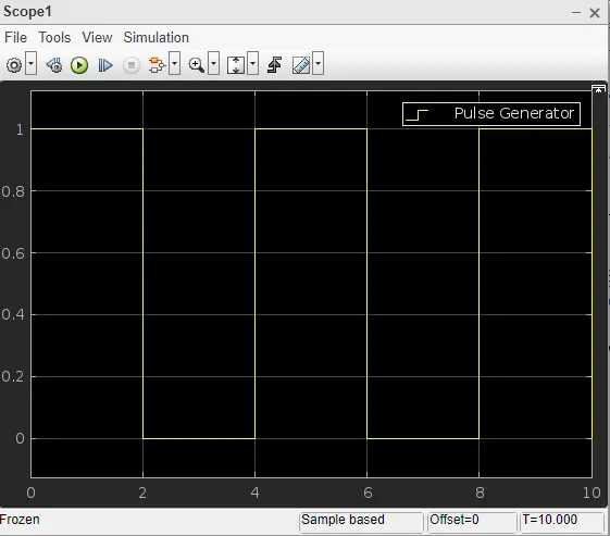
- The doorbell system is designed by using a solenoid block as shown in the image file attached. In this system, with the help of a pulse generator, we can able to generate a pulse signal to switch for 2 sec, and then the signal is released.
- To apply this signal to the switch as it is a physical block we need a Simulink to the physical signal converter.
- When the switch is made on the solenoid receives an electrical signal and makes the plunger create a displacement from its original position according to its own properties.
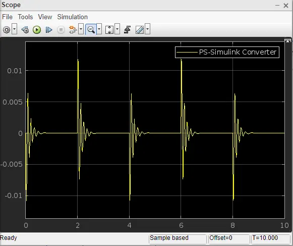
- This physical displacement was caught by using an ideal translational motion sensor, with the help of a scops this system performance can be observed.
- https://drive.google.com/file/d/1tKQ7lF3Okh-R41IYV20ysQPpoHd-fQZ2/view?usp=sharing
2)
Aim: Fan speed control by using a thermistor using the given below-mentioned condition.
According to the given condition of the fan, the below table shows tabular information regarding the operating status of the fan controlled by a dc motor.
Fan Operating Condition
|
Time Duration(in Sec) |
Temperature (In Deg ) |
Status of Fan (On/Off) |
| 0-10 | 20 c | Off |
| 10-30 | 27 c | On |
| 30-50 | 23 c | Off |
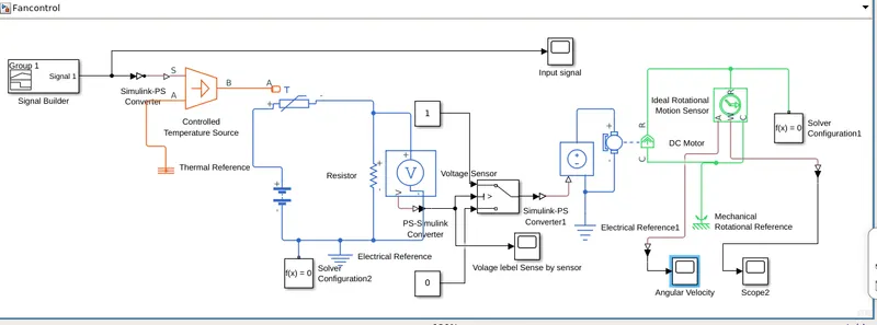
- The below-shown Simulink model shows the speed control of the fan using a thermister.
- In the below model shown we have used a signal generator block which will help us to design our necessary signal as per our requirements.
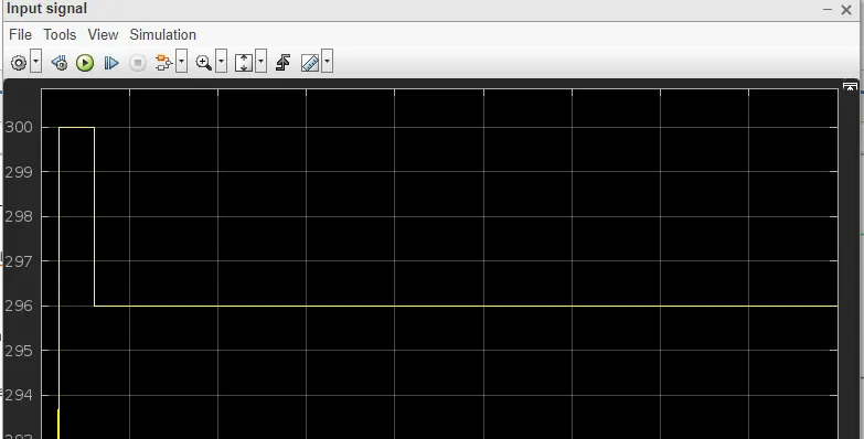
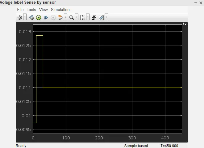
- Based on the voltage level sensed by the voltage sensor we can select the threshold value of the switch.
- The switch with the help of a controlled voltage sensor will control the speed of the dc motor which will control the speed of the fan.
- Solver configuration is used in every physical model as it a necessary tool for all the physical models.
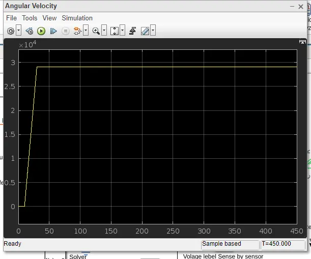
- Final Output.
-
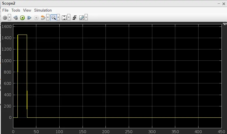
- The Google drive link is provided for your reference.
- https://drive.google.com/file/d/1fGEw0aVz5HivLxhZbVTm2L-gWA-4JFFt/view?usp=sharing