Project
Aim: Technical Report explaining the Simulation model of the all-terrain vehicle system and its model properties.
Objective:
To prepare a technical report on the BAJA All-terrain vehicle system for the following categories,
1) BAJA ATV model without the dashboard.
2) BAJA ATV model with the dashboard.
3) BAJA ATV model with the use of lookup table without the dashboard.
4) BAJA ATV model with the use of lookup table with the dashboard.
- All-terrain Vehicle (AVT)
- An all-terrain vehicle (ATV) is defined as a motorized vehicle that is designed to travel on four low-pressure and non-pneumatic tires, with a seat designed to be occupied by the operator along with handlebars provided for steering control.
- The AVT is also known as a light utility vehicle, a quad bike, or simply a quad, as defined by the American National Standards Institute (ANSI). An ATV is designed to handle a broader variety of terrain as compared to regular vehicles. However, AVT is not street-legal or roadworthy in some countries.
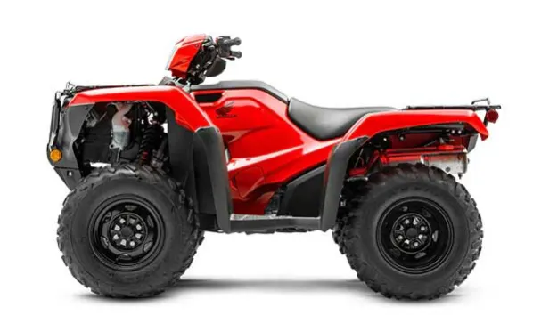
- Different types of AVTs
| Type | Application | Engine type | Drive type | Fule type |
| Utility AVT | Agricultural Industries | 800cc | 2WD | Gasoline AVT |
| Sports AVT | Sports | 250cc-700cc | 4WD | Electric AVT |
| Recreational AVT | Military and Defence | >800cc | AWD | |
| Side by side | Transportation and Mobility | 1000cc |
2. Continuously Variable Transmission (CVT):
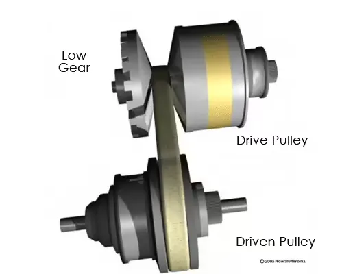
- A continuously variable transmission (CVT) is an automatic transmission that can change seamlessly through a continuous range of gear ratios.
- This contrasts with other transmissions that provide a limited number of gear ratios in fixed steps.
- The flexibility of a CVT with suitable control may allow the engine to operate at a constant "RPM" while the vehicle speed keeps on changing., Unlike traditional automatic transmissions, continuously variable transmissions don't have a gearbox with a set number of gears, which means they don't have interlocking toothed wheels.
- The most common type of CVT operates on an ingenious pulley system that allows an infinite variability between highest and lowest gears with no discrete steps or shifts.
03) Explanation
PART#01) BAJA AVT MODEL WITHOUT USING LOOKUP TABLE.
1.1)BAJA ATV SIMULINK MODEL WITHOUT DASHBOARD.
- Simulink model for BAJA AVT is given below,
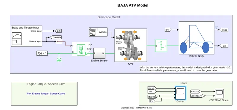
Blocks used in the above model,
Signal Builder:
- The Signal Builder block allows you to create interchangeable groups of piecewise linear signal sources and use them in a model.
Generic Engine:
- The Generic Engine block represents a general internal combustion engine. This block is a suitable generic engine for spark-ignition and diesel. Speed-power and speed-torque parameterizations are provided.
- A throttle physical signal input specifies the normalized engine torque. Optional dynamic parameters include crankshaft inertia and response time lag.
- A physical signal port outputs the engine fuel consumption rate based on the fuel consumption model that you choose.
- Optional speed and redline controllers prevent the engine to stall and enable cruise control.
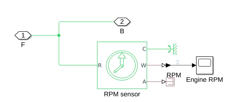
Engine Sensor:
Ideal Rotational Motion Sensor :
- The Ideal Rotational Motion Sensor block represents an ideal mechanical rotational motion sensor, that is, a device that converts an across variable measured between two mechanical rotational nodes into a control signal proportional to angular velocity or angle.
- The sensor is ideal since it does not account for inertia, friction, delays, energy consumption, and so on.
Simple Gear:
- The Simple Gear block represents a gearbox that constrains the connected driveline axes of the base gear, B, and the follower gear, F, to corotate with a fixed ratio that you specify.
- We choose whether the follower axis rotates in the same or opposite direction as the base axis. If they rotate in the same direction, the angular velocity of the follower, ωF, and the angular velocity of the base, ωB, have the same sign.
- If they rotate in opposite directions, ωF and ωB have opposite signs. We can easily add and remove backlash, faults, and thermal effects.
CVT Model:
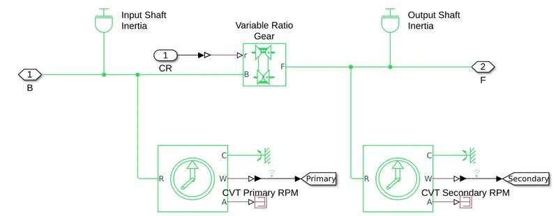
Inertia:
- Inertia is the resistance of any physical object to a change in its velocity.
- This includes changes to the object's speed or direction of motion.
Variable Ratio Transmission:
- The Variable Ratio Transmission block represents a gearbox that dynamically transfers motion and torque between the two connected driveshaft axes, the base and the follower.
- When we choose to have the block ignore the dynamics of transmission compliance, it constrains the driveshafts to corotate with a variable gear ratio that we control.
- We can choose whether the follower axis rotates in the same or opposite direction as the base axis. If the follower and base axis rotate in the same direction, ωF and ωB have the same sign.
- If the follower and base axis rotate in opposite directions, ωF and ωB have opposite signs.
- With the increase in gear ratio between follower and base, the ratio of the follower to base angular speed decreases and conversely the ratio of the follower to base torque increases with a gear ratio.
Vehicle body model:
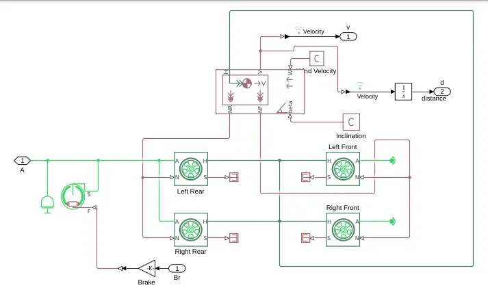
- Parameters of Vehicle body:
- Mass: 250 Kg.
- No of wheels per axel: 02
- Horizontal distance from CG to front axel: 1m
- Horizontal distance from CG to rare axel 0.35m
- CG height above ground:0.7m
- Gravitational acceleration: 9.8 m/s^2
Tire:
-
The Tire (Magic Formula) block models a tire with longitudinal behaviour given by the Magic Formula [1], an empirical equation based on four fitting coefficients. The block can model tire dynamics under constant or variable pavement conditions.
-
The longitudinal direction of the tire is the same as its direction of motion as it rolls on the pavement.
-
To increase the fidelity of the tire model, you can specify properties such as tire compliance, inertia, and rolling resistance. However, these properties increase the complexity of the tire model and can slow down the simulation.
Double-Shoe break:
- The Double-Shoe Brake block represents a frictional brake with two pivoted rigid shoes that press against a rotating drum to produce a braking action. The rigid shoes sit inside or outside the rotating drum in an opposed configuration.
Scope:
- This block is used for displaying signals generated during the simulation process.
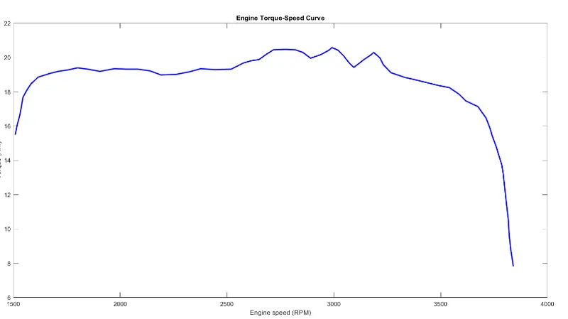
Engine Torque vs Speed Curve
#Input:1.1
- Break and Throttle input:
- Break input is zero throughout the simulation.
- Throttle input I have given 0.5 for the first 30sec and then changes to 1 at 30sec and remains 1 for the entire duration of the simulation.
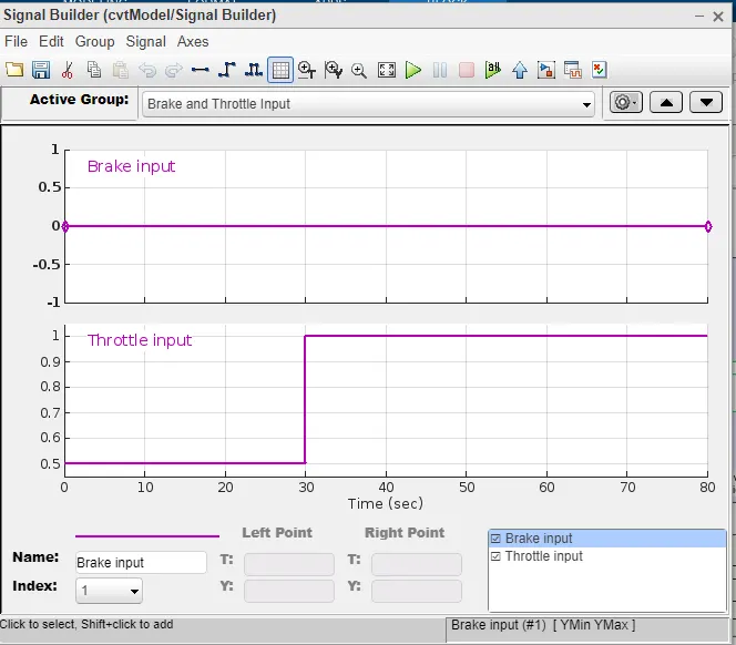
- The throttle value is mainly to control the amount of flow of fuel into the engine if the throttle value increases the flow of fuel increases to the IC engine which in turn increases the power of the engine.
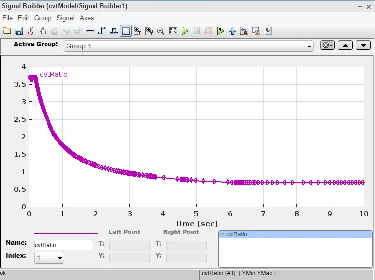
CVT Gear Ratio:
Output 1.1:
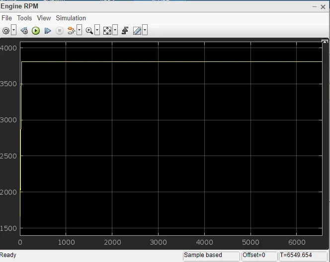
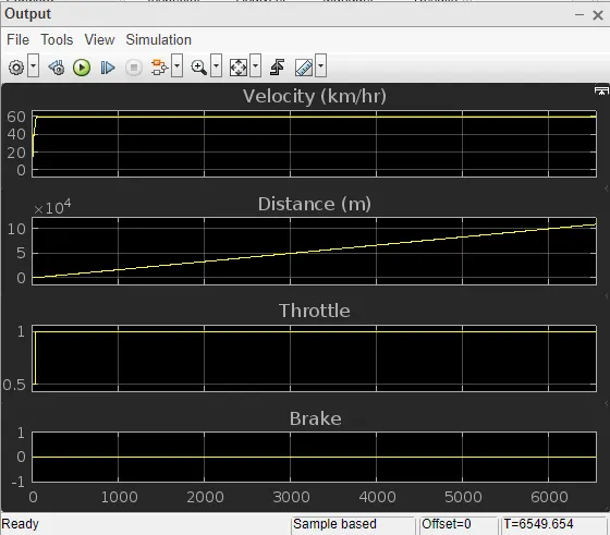
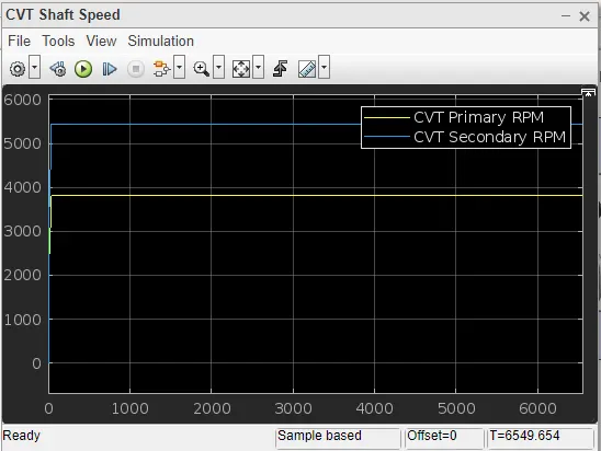
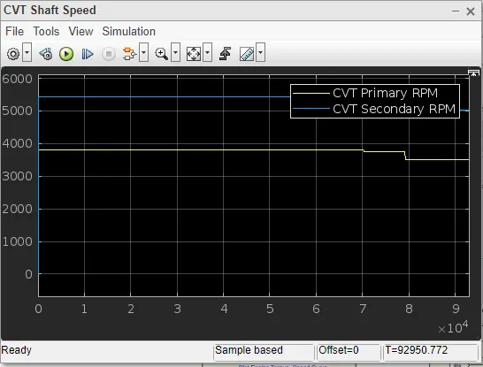
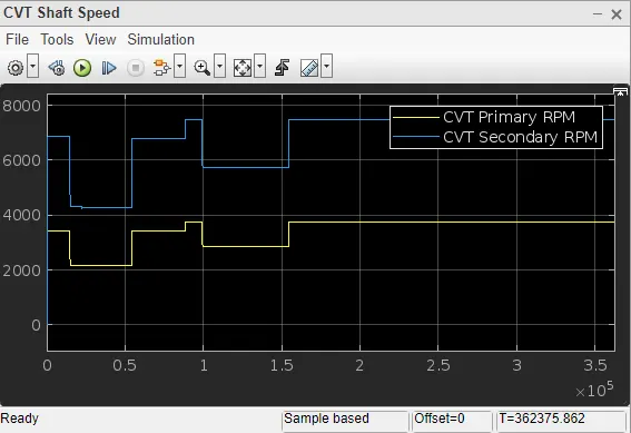
- In the above figure, the break input is maintained at constant while the other is that throttle input is varied from .5 to 1 at 30 sec and remains at 1 for the entire duration. With this change in throttle input, there is a change in the CVT shaft speed of the ATV which is shown below.
1.2) BAJA ATV SIMULINK MODEL WITH DASHBOARD
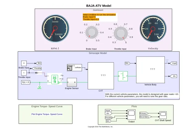
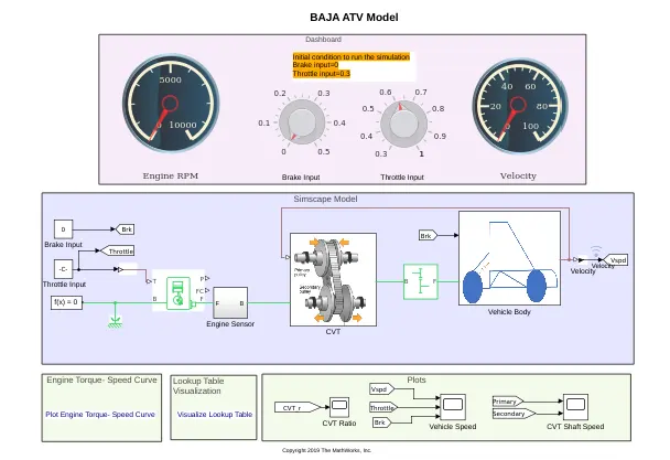
- A Simulink model for BAJA ATV with the dashboard is shown below. Likewise, without a dashboard, all the blocks are common other than the dashboard.
Dashboard:
- Dashboard displays the percentage of members labelled and the label value distribution of the selected label definition.
- In Signal Labeler, you can monitor labelling progress and inspect statistics about your labels using the Dashboard. You can display different charts to quickly determine how many members are labelled, analyze the distributions of each label, and confirm the data is labelled correctly.
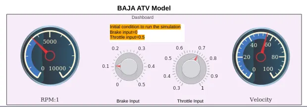
- The initial conditions are,
- Break input= 0
- Throttle input = 0.5
- Simulink Model
Knob:
- The Knob block tunes the value of the connected block parameter during simulation. For example, we can connect the Knob block to a Gain block in your model and adjust its value during simulation.
- We can modify the range of the Knob block's scale to fit your data during run time.
- Use the Knob block with other Dashboard blocks to create an interactive dashboard to control your model.
- A variable knob is used unlike a signal builder in the previous case by which we can able to apply the input signals.
#Input 1.2:
Output 1.2:
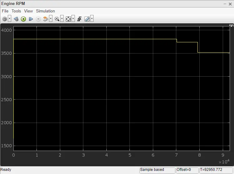
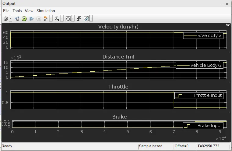
CVT Shaft Speed:
PART#02) BAJA ATV WITH THE USE OF LOOKUP TABLE
2.1) BAJA ATV Simulink model with a lookup table but without a dashboard
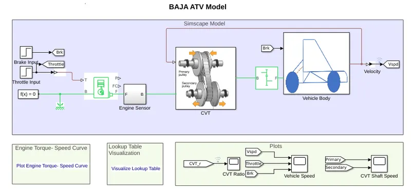
Lookup Table Block:
-
A lookup table is an array of data that maps input values to output values, thereby approximating a mathematical function.
-
Given a set of input values, a lookup operation retrieves the corresponding output values from the table.
-
If the lookup table does not explicitly define the input values, Simulink® can estimate an output value using interpolation, extrapolation, or rounding, where:
-
Interpolation is a process for estimating values that lie between known data points.
-
Extrapolation is a process for estimating values that lie beyond the range of known data points.
-
A Rounding is a process for approximating a value by altering its digits according to a known rule.
-
- A lookup table block uses an array of data to map input values to output values, approximating a mathematical function.
- Given input values, Simulink performs a “lookup” operation to retrieve the corresponding output values from the table.
- If the lookup table does not define the input values, the block estimates the output values based on nearby table values.
CVT Model:
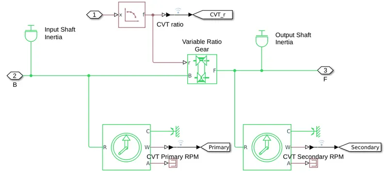
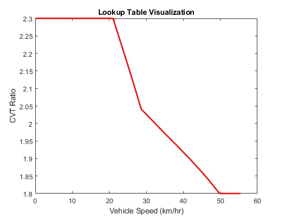
- In place of CVT gear ratio input a lookup table is assigned in the model below, which needs to be loaded with the file name Lookuptable_data.mat.
#INPUT 2.1
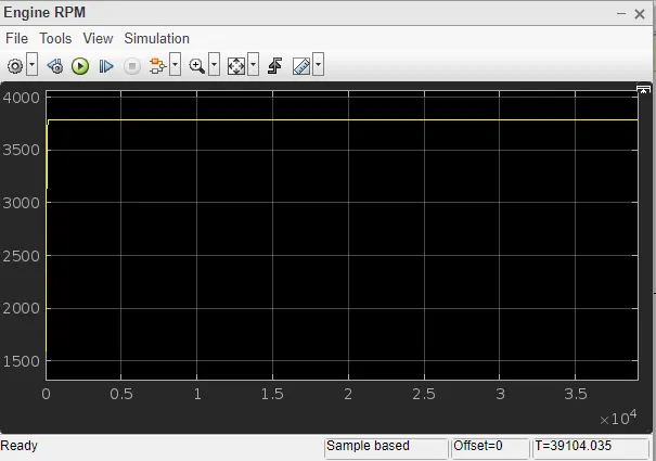
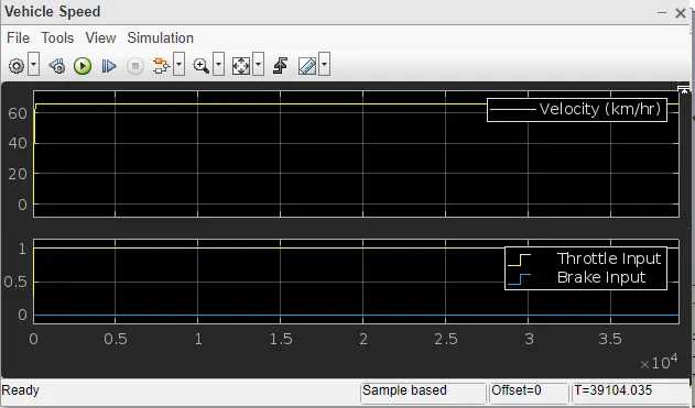
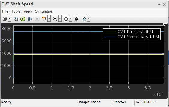
- These inputs are provided in steps using a step block.
| PARAMETERS | BREAK INPUT | THROTTLE INPUT |
| Step time | 35 | 20 |
| Initial Value | 0 | 0.3 |
| Final Value | 0 | 1 |
| Sample time | 0 | 0 |
Output 2.1:
2.2) BAJA ATV Simulink model with a lookup table and with a dashboard
- A Simulink model of BAJA ATV with both using a lookup table and a dashboard is shown below.
#INPUT 2.2:
- Inputs for this model are provided by a Knob which can be varied, unlike the signal builder. Both throttle and brake inputs were provided by the knob.
- The engine rmp gauge and velocity gauge displays the changes made by the knob.
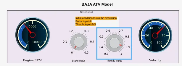
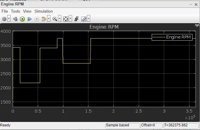
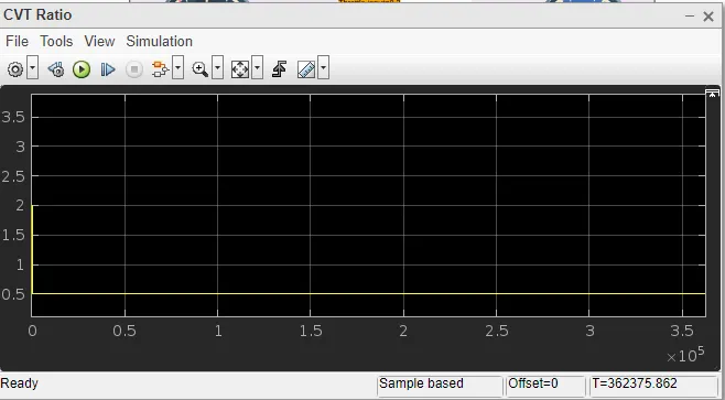
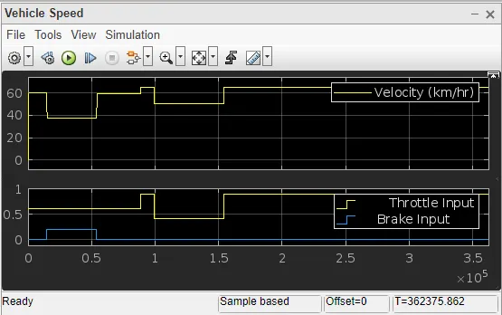
- Outputs are shown according to the above-shown input, these inputs are provided during the run time with the help of the knob.
Output 2.2:
Conclusion:
- From the above simulation models of the ALL-TERRAIN VEHICLE (AVT) system using Continuously Variable Transmission (CVT) I have concluded that with a change in throttle input the fuel input to the engine increase due to which the power of the engine increases which increases the velocity of engine. When breaking input increases that reduce the speed and hence reduces the engine power. Therefore engine power is inversely proportional to brake input.
- Torque decreases with an increase in speed but after a certain time torque starts decreasing in order to achieve the maximum speed.
- With the help of the lookup table we can provide any input value and the corresponding output can be observed by using interpolation and extrapolation methods.
- All the above four models are checked with the variation in break input and throttle input and the outputs are shown in the above.