Project - Position control of mass spring damper system
Aim:
To build the Simulink model of the Spring Mass Damper System with the Help of the transfer Function and adjust the force applied to the mass with the help of the PID Controller.
Procedure:
Force Equation for Spring Damper Mass System is
f(x) = m*x_dotdot + c*x_dot +k*x --------> (1)
where ' m ' is the mass of the Body
' k ' is the Spring stiffness constant
' c ' is the Damping Constant.
Apply Laplace transform on both sides of equation (1)
therefore
F(S) = m*s² *X(s) + c*s*X(S) + k*X(S)
where F(S) is the transfer function of the f(x)
X(S) is the transfer function of the x(t)
F(S) = X(S) [ m*s² + c*s + k ]
X(S)/F(S) = 1/ [ m*s² + c*s + k ] ----->(2)
equation (2) is the transfer function of the spring mass damper system.
Given Data:
mass " m " = 3.6 kg
Spring constant " k " = 400 N/m
Damping constant " c " = 100 Ns/m
We know state matrix and Input matrix for the spring mass damper system are
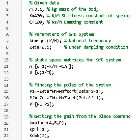
A = [ 0 1; -k/m -c/m ]; A is the state matrix
A = [ 0 1; -111.111 -27.7778];
B = [ 0 ; 1/m ] ; B is the Input matrix
B = [ 0 ; 0.2778 ] ;
let say zeta = 0.5 (under damped condition )
angula frquency "wn" = sqrt (k/m) = 10.5409;
To finout the poles the following formula is used
P1 = -zeta * wn + wn *sqrt (zeta²-1);
P2 = -zeta * wn - wn *sqrt (zeta²-1);
P = [ P1 P2 ];
Now we need to findout the Gains of the system like propotional gain and derivative gains using the place command
therefore >> K = place(A,B,P)
where " A " is the state matrix of the Spring Mass Damper System.
" B " is the Input matrix of the Spring Mass Damper System.
" P " is the poles of the system
" K(1) " is the propotional Gain
" K(2) " is the derivative Gain
Building the Simulink model for positon control of Spring Mass Damper System with the Help of the Given Data
Block required for the Model are:
1. Pulse Generator Block : Used To give reference signal to the mass Spring Damper System.
2. Sum Block : Used To add the Simulink Signals
3. Gain Block: Gain Block is used to muliply the signal with a constant gain value.
4. Integrator Block: Integrator Block is Used to Integrate Input signal to it to get the required output of the signal.
5. Derivative Block: Derivative Block is used to Differentiate the input signal with respect to time.
6. Scope Block: Scope Block is Used to plot the required signal with respect to time
7. Transfer function Block: The transfer function block models a linear system by a transfer function of the Laplace-domain variable S. The Block can model single-input singleoutput(SISO) and single-input multiple-output(SIMO) systems
Modeling a Single-Output System
For a single-output system, the input and output of the block are scalar time-domain signals. To model this system:
1. Enter a vector for the numerator coefficients of the transfer function in the Numerator coefficients field.
2. Enter a vector for the denominator coefficients of the transfer function in the Denominator coefficients field.
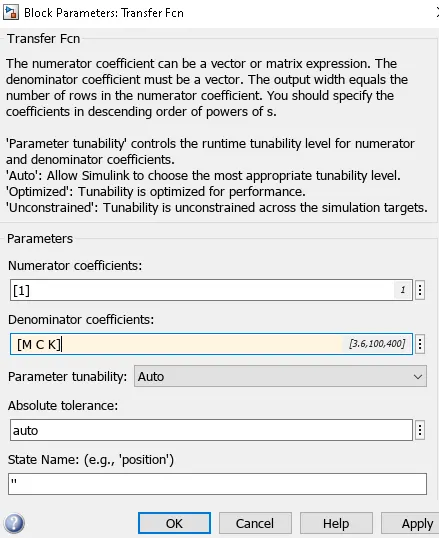
Writing the matlab code for the model position control spring mass damper system is shown below
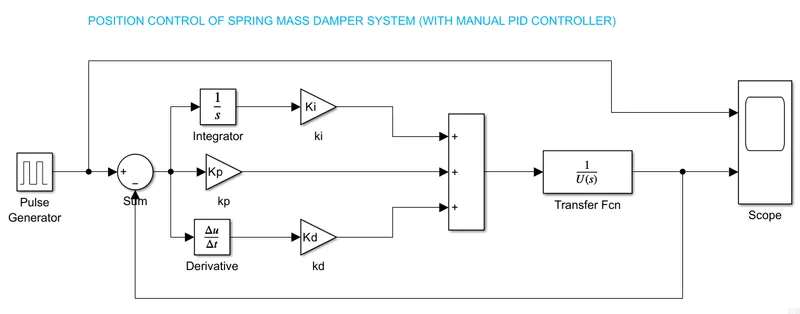
Simulink Model for the Position control of Spring Mass Damper System with manual PID Controller
Explanation:
- Here we subtracting the reference Signal from the Feedback Signal and the resulting signal is represented as the error Signal.
- Error Signal is Passes through the PID Controller with Proportional Integral and Derivative gains.
- In the Function Block set the Denominator Coefficients mass " m ", Damping Coefficient " c ", and Spring Constant " k ".
- The Out-put signal (displacement ) is connected with the scope block to view the result and the sum block to generate an Error signal.
Result:
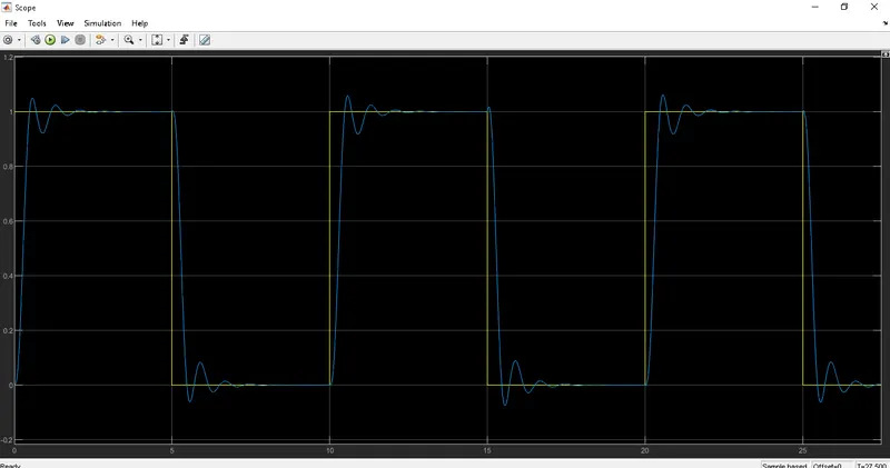
1.IF KI=1375
After Running the Model we are getting the below-resulted scope
The Rise time is less than one second , Overshoot is less than 5 % and the settling time is less than 2 seconds.
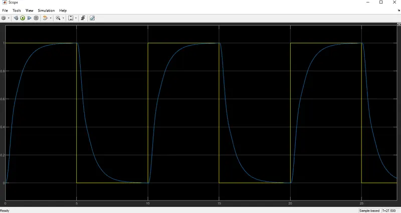
2.IF KI=500
After Running the Model we are getting the below-resulted scope
The Rise time is less than five second , Overshoot and undershoot allmost zero , settling time is less than 5 seconds.
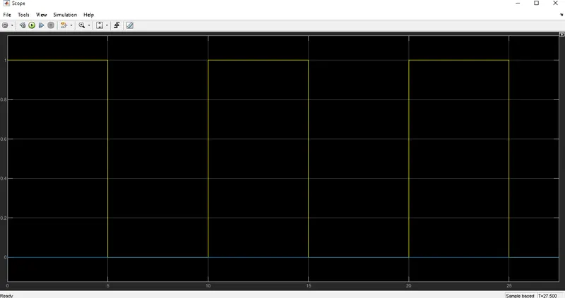
3.IF KI=0
After Running the Model we are getting the below-resulted scope
There no overshoot and undershot curve comes equql to zero
Conclusion:
Transfer function of the spring mass damper system is derived and PID gains are obtained from the 'place' command with the given data. simulink model builded and result are obtained to gets the stability.