Project - Position control of mass spring damper system
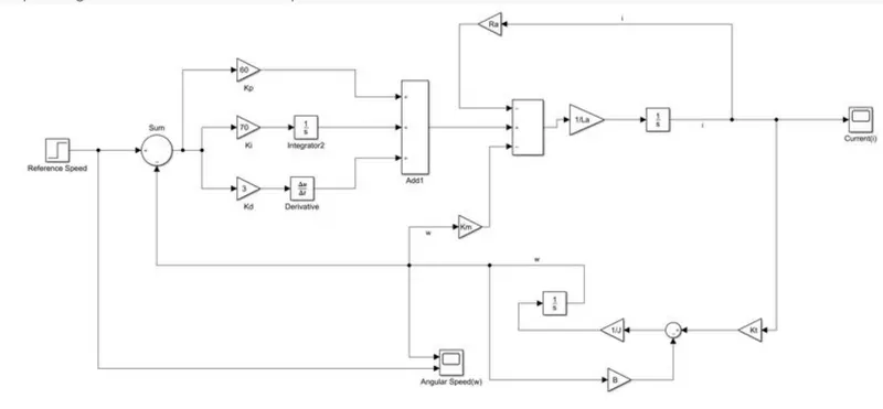
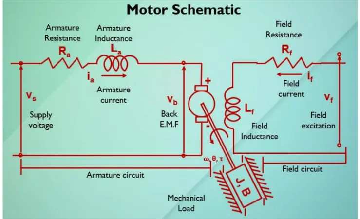
In this project, a Simulink model for the DC motor will be first developed per the schematic shown in Figure 1.
Use the Proportional, Integral, and Derivative (PID) control design knowledge gained in the training to design, develop
and test a controller to maintain a desired speed for the motor.
Key Highlights:
Mathematical modeling from the first principles
Modeling an Electrical Engineering system
Simulink based modeling
Control law design and test
Stability of a dynamic system
Deliverables:
Matlab script to define modeling and control design parameters
Simulink model to simulate and verify the design
Your Answers
Speed Control of a Direct Current (DC) motor
Design parameters of DC Motor :
J = 0.01 : moment of inertia in kg-m^2
B = 0.1 : Motor viscous friction constant in N-m-s
Km = 0.01 : back EMF constant in v/rad/s
Kt = 0.01 : Motor torque constant in N-m/amp
Ra = 1 : Resistance of armature circuit in ohms
La = 0.5 :Inductance of the armature circuit in henries
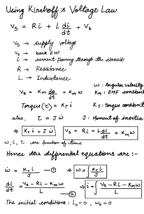
Mathematical Modelling :
MATLAB Script for the design parameters:
% Design parameters of DC Motor
J = 0.01; % moment of inertia in kg-m^2
B = 0.1; % Motor viscous friction constant in N-m-s
Km = 0.01; % back EMF constant in v/rad/s
Kt = 0.01; % Motor torque constant in N-m/amp
Ra = 1; % Resistance of armature circuit in ohms
La = 0.5; %Inductance of the armature circuit in henries
r = roots([J*La (J*Ra + B*La) (B*Ra + Kt*Km)]);
A = [-B/J Kt/J; -Km/La -Ra/La];
B1 = [0; 1/La];
K = place(A,B1,r);
Kp = K(1);
Kd = K(2);
Ki = 15;
Poles : -9.9975, -2.0025
From the pole placement method:
Kp = -1.4762e-15
Kd = 2.2204e-16
Control Design Objectives :
1. Settling Time < 2 seconds
2. Overshoot < 5%
3. Steady State Error < 1%
Using the pole placement method , the control design objectives were not met, hence after several trial and errors,
Kp = 60, Ki = 70 , Kd= 3 are taken for finer feedback control.
Now,
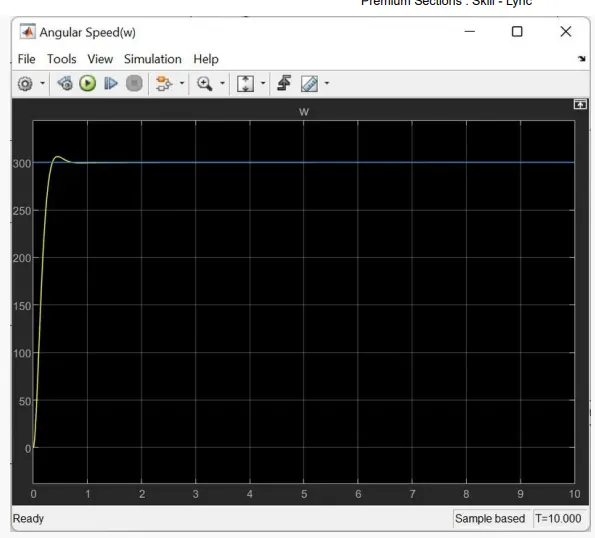
For reference, a step input of speed of 300 rpm, initial value = 0 and step time = 0 was taken
Sample Time = 10 seconds
Solver for modelling : RK4 ( Runga-Kutta)
Fixed Step Size = 0.001
Blue : Reference
Yellow : Output Speed
Observations from the output speed :
1. Settling Time < 1 sec (less than 2 sec)
2. Overshoots to 310 rad/sec, then settles to 300 for the rest of the time
[(310-300)/300] *100 = 3.33% overshooting ( less than 5%)
3. Steady state error = 300-300 = 0 ( less than 1%)
Hence, the control design objectives are met.
Blocsks used :
Step , Integrator, Derivative, Gain, Scope, Sum , Add