Project 1
Your Answers
Modeling a Double-Acting Actuator
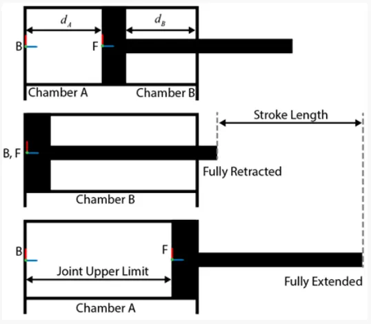
Double-Acting Actuator
In a double acting setup, the design requires the force of the instrument air pressure to both thrusts the pistons apart as
well as to push the pistons together. In other words, this design requires supplied air to complete both the actions of
opening and closing the subject, hence the term double acting valve This function utilizes two air supply ports
integrated into the design of the housing.
One port allows air to access the chamber between the two pistons. Supplying sufficient air pressure here will force the
pistons apart and rotate the pinion in one direction. The second port allows air to access the space on the opposing
faces of the pistons. Supplying air pressure here, will push the pistons together and rotate the pinion in the opposite
direction.
Oftentimes, a valve assembly may include the installation of a solenoid to govern the supply air to these ports so that an
electric signal may govern the opening and closing of the valve by means of this solenoid actuator interface.
Advantages of Double Acting Actuators
though the presence of springs remains a benefit in terms of offering a fail position, the absence of springs in the
double acting design also presents an advantage in terms of size and weight. While the actuator valve interface
typically remains similar between the two types, double acting devices prove significantly lighter, frequently less
expensive, and often smaller in profile, especially in larger sizes, since they do not need to accommodate hefty springs.
Also, the force required to stroke a valve open using a double acting setup only needs to overcome the torque intrinsic
to the valve and the process, while a spring return configuration must also combat the opposing force of the springs
themselves.
Model
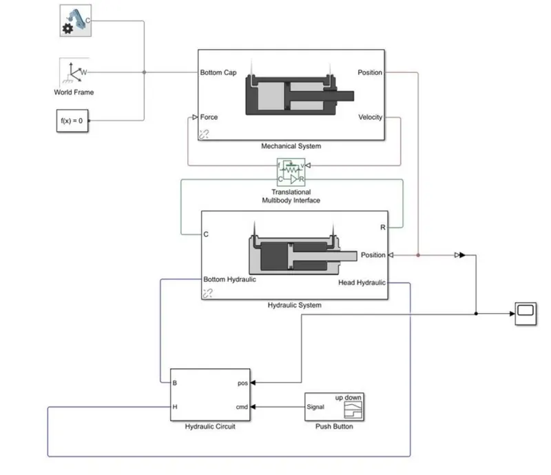
Mechanical System

Hydraulic System
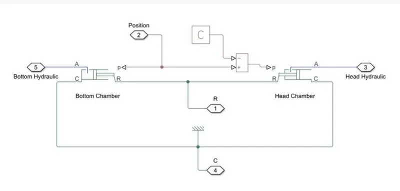
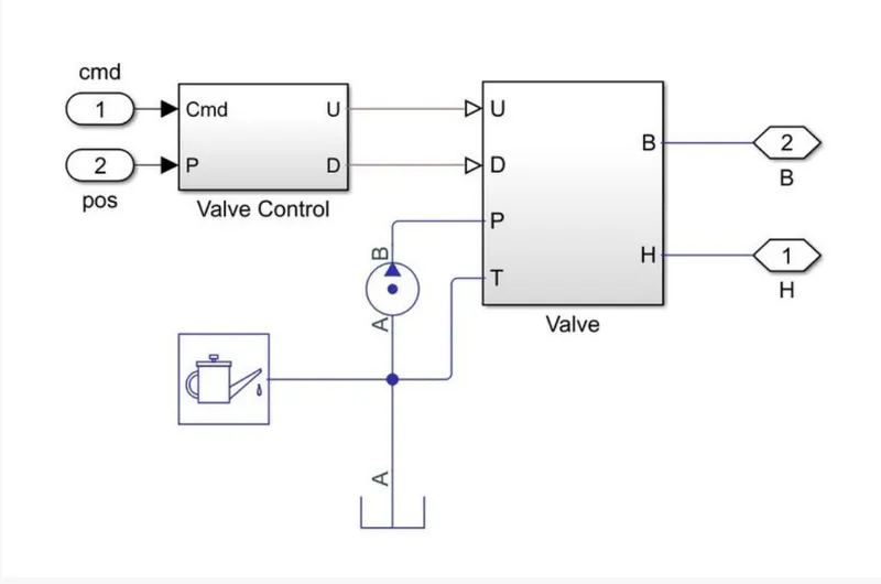
Hydraulic Circuit
3D Assembly Model
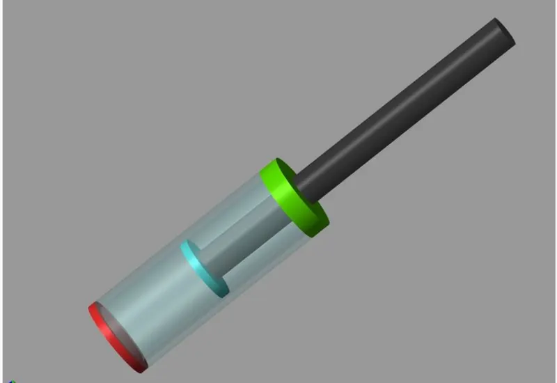
3D parts :
Cylinder Assembly - Bottom Cap, Barrel, Head Cap
Piston Assembly - Pistopn, Rod
Initial liquid pressure of Both bottom chamber and Head Chamber is 4e6 Pa
Fluid Properties:
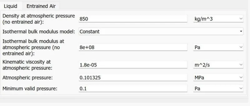
Stroke length = 0.45 m
Results:
Input Signal to the Valve: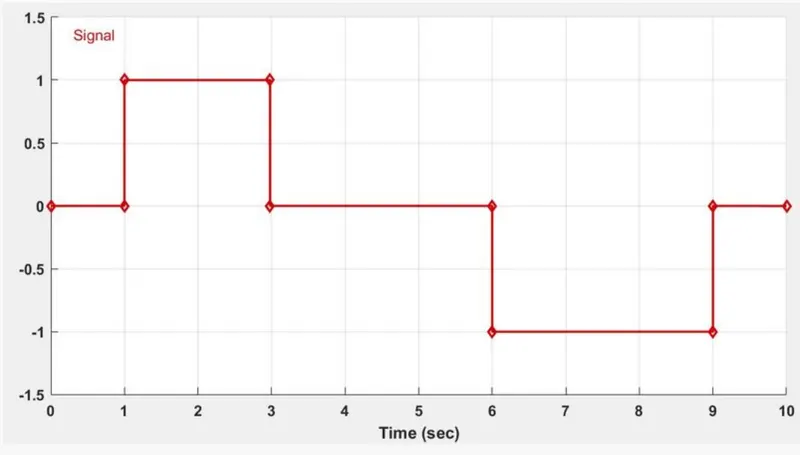
Resulting postion of the Piston (Actuation):
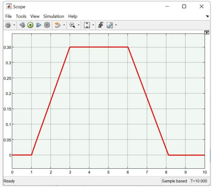
Observations :
The graph of the position of the piston rises then becomes steady and then falls, this shows that the piston is
moving/reciprocating from bottom dead cenre to top dead centre and again to bottom, in accordance with the input
signal.