Project - Position control of mass spring damper system
Aim:To design the transfer function of mass spring damper system and add a pid controller.
Objectives:
Obtain the transfer function of a mass spring damper system and use it in the model. Add a PID controller to adjust the force on mass so that its position follows a reference signal.
Take m = 3.6; %kg k = 400; %N/m c = 100; %Ns/m
Procedure:
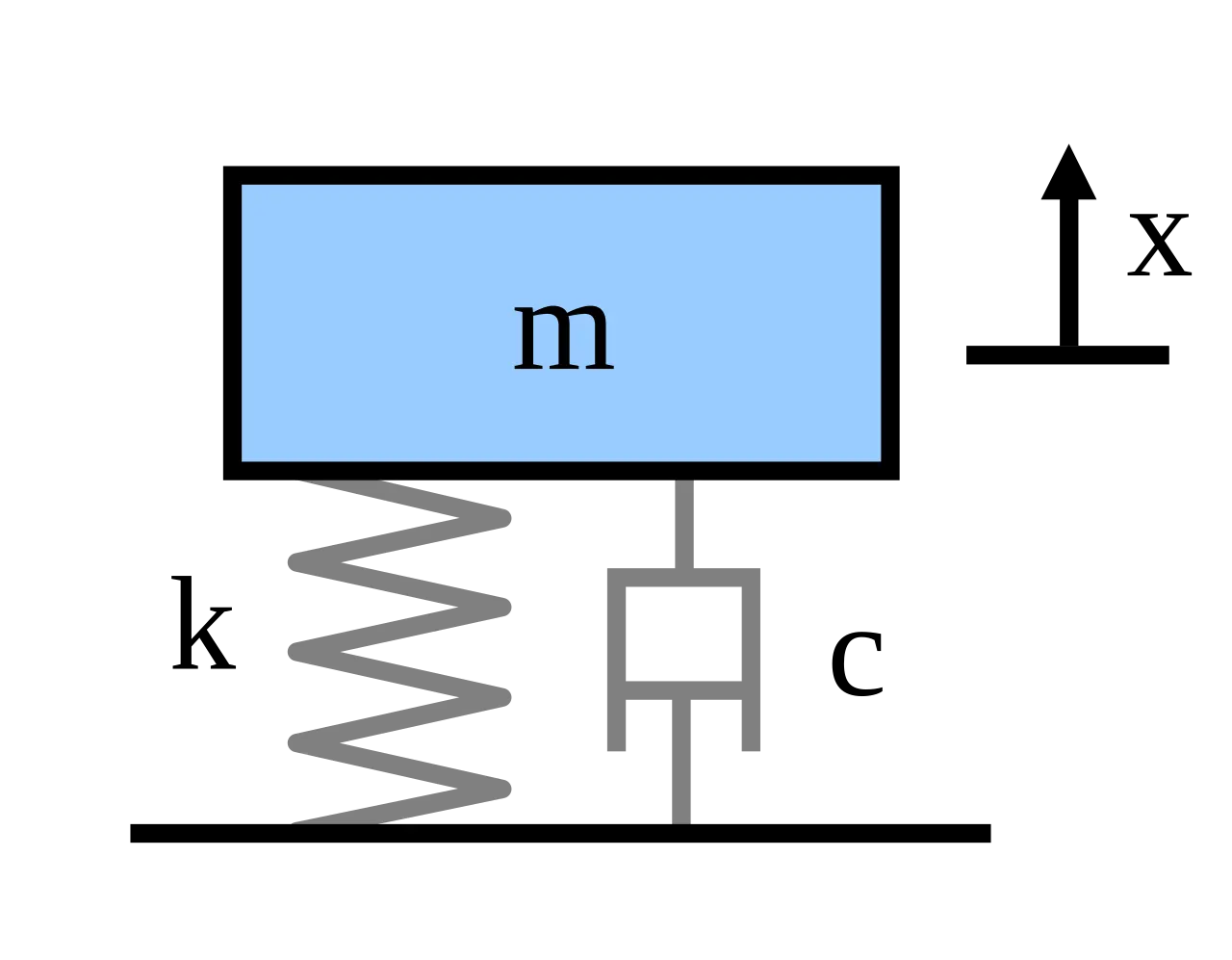
The mass-spring-damper model consists of discrete mass nodes distributed throughout an object and interconnected via a network of springs and dampers. This model is well-suited for modelling object with complex material properties such as nonlinearity and viscoelasticity. Packages such as MATLAB may be used to run simulations of such models.As well as engineering simulation, these systems have applications in computer graphics and computer animation.
Trasnfer function:
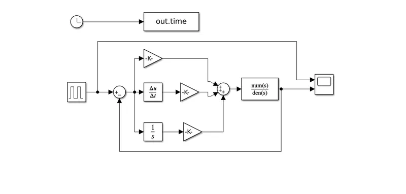
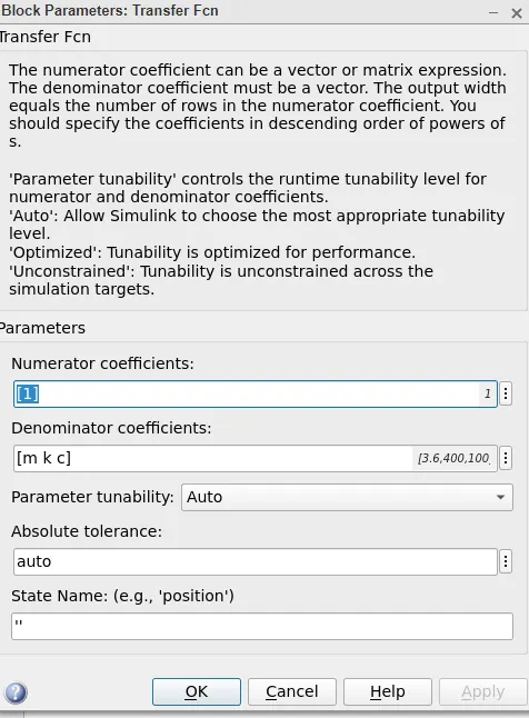
The first thing is setting up the transfer function.Set the initial velocity as 10m/s.The controller adjust the force applied by itself. Trasnfer function of a mass spring damper system and use it in the model. Add a PID controller to adjust the force on mass so that its position follows a reference signal. The matlab model of the pid control and transfer function pulse wavefrome generator.
PID controller:
In this project, a mass spring damper system that may move in any direction is being controlled by a PID controller that was created using Simulink. On the diagram, a dc motor transfer function has been added. Through adjusting, the PID controller's response curve was fixed. The computer interface makes it simple to perform various control algorithms on the system; control parameters can be set up online; filter methods can be tested in a variety of structures; and the system's response to these modifiable values can be seen. Controller Proportional Integral Derivative's (PID) influence on creating the model.
Pole placement:
Position control system design:
Following Parameters
The model in the previously produced model needs to undergo the following adjustments in order to design a closed loop control system for a DC motor.
Since speed is the variable that may be controlled, we will set the reference speed in step block to 10, 20, or 40, as desired.
To create the error signal e, subtract the actual speed from the reference speed (t)
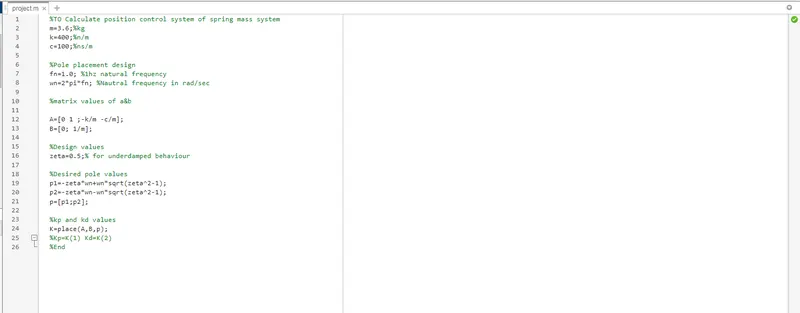
Kd and Kp, which are parameters determined by the place command (K=place(A,B,P)), should be added. (Use the gain block to mention Kp, Kd, and Ki values.)
The output current of the plant or model serves as the source of feedback for Kd (figure 1). Alternatively, we can accept comments (error speed signal as input to Kd shown by figure 2)
Ki can be manually added with a gain and integrator block, and different values of Ki can be tuned to see how the results are affected.
The following command ('pzmap '-pole zero placement or mapping) can be used in addition to the script above to check the positions of poles on the s-plane in MATLAB. Two crosses in red that show complicated poles lying on the left side of the plane suggest that the system is stable.