Project - Analysis of a practical automotive wiring circuit
Assuming battery voltage as 12V
1. The major parts are listed below
- Generator
- Starter
- Battery
- Ignition coil
- Circuit Breaker
- Distributor
- Current and Voltage regulator
- Ignition switch
- Fuse
- Ammeter
- Foot selector switch
- Gas tank unit
- Light switch
- Lamps
- Horns.
2. Working principles of Generator Starter and Ignition coil
In automotive systems, the generator starter and ignition coil both play crucial roles in ensuring the engine starts and operates smoothly. Let’s break down their functions and purposes: The starter motor (also referred to as the starter) is responsible for initiating the engine’s operation. Its primary purpose is to turn the engine over (crank the engine) to start the combustion process. Once the engine starts running, the starter motor is disengaged. Once the engine is running, the starter motor no longer plays an active role, and it only needs to engage when you start the vehicle. The ignition coil is a vital component of the ignition system in internal combustion engines. Its main purpose is to convert the 12V from the battery into a much higher voltage (usually around 12,000 to 45,000 volts) required to create a spark in the spark plugs, which ignites the air-fuel mixture in the engine’s cylinders. Function: Operation Timing: Together, both the starter motor and the ignition coil are crucial for starting and maintaining the engine’s operation.2. Starter (Starter Motor)
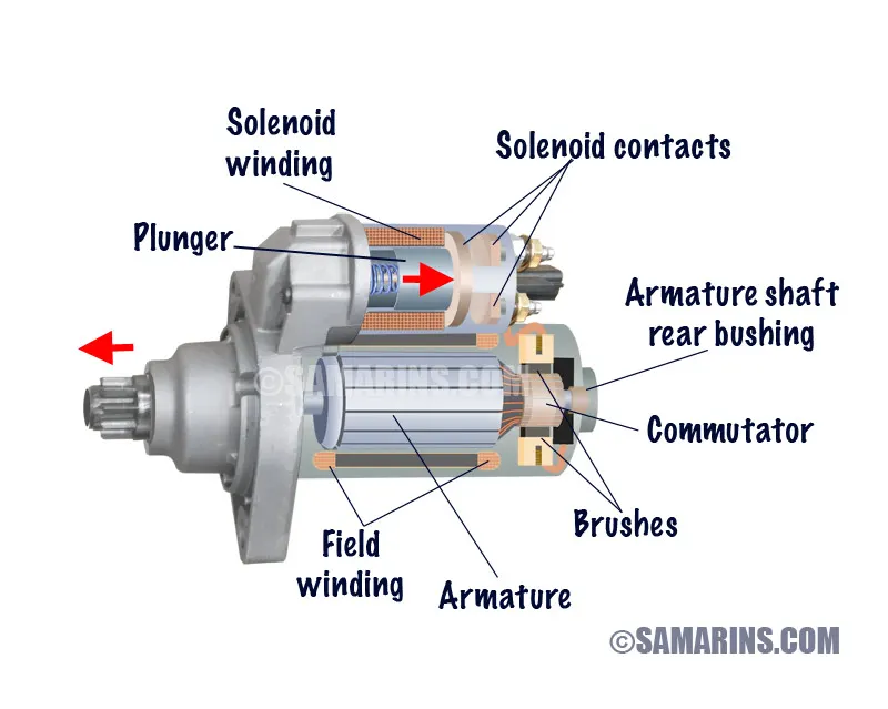
Purpose:
Working:
Summary of Purpose:
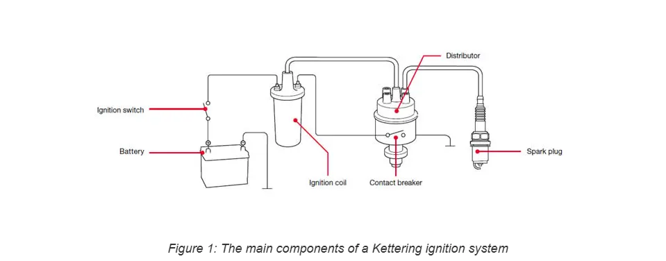
2. Ignition Coil
Purpose:
Working:
Summary of Purpose:
Key Differences Between Generator Starter and Ignition Coil:
Generator in Automobiles:
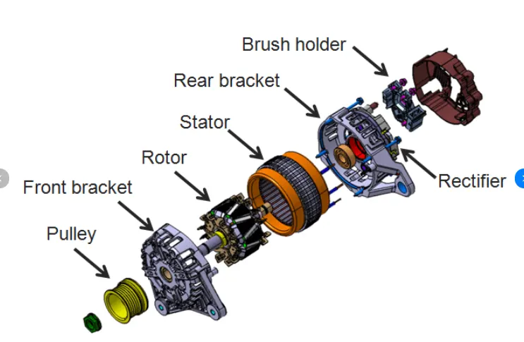
In automobiles, the term generator generally refers to an alternator. The alternator is a crucial component in modern vehicles, responsible for charging the battery and supplying electrical power to the vehicle’s electrical systems while the engine is running.
Purpose of the Alternator (Generator):
The primary purpose of the alternator in an automobile is to:
Working of the Alternator (Generator):
The alternator works on the principle of electromagnetic induction, which states that a current is induced in a conductor when it moves through a magnetic field. Let’s break down the process:
Components of an Alternator:
- Stator: The stationary part of the alternator that generates alternating current (AC). It consists of windings (coils of wire) that are arranged around the rotor.
- Rotor: The rotating part of the alternator. It is a magnet (or contains electromagnetic windings) that rotates inside the stator.
- Slip Rings: Conductors that maintain electrical contact between the rotor and the external circuits.
- Rectifier (Diodes): Converts the alternating current (AC) generated in the stator into direct current (DC) to charge the battery and power the car’s electrical systems.
- Voltage Regulator: Maintains the output voltage of the alternator at a constant level (usually around 14V) to prevent overcharging or undercharging the battery.
The Alternator’s Working Process:
- Magnetic Field Creation: When the engine is running, the engine drives a belt connected to the alternator’s pulley. This belt turns the alternator’s rotor.
- Rotation of Rotor: As the rotor spins inside the stator, it creates a magnetic field that induces an electrical current in the stator’s coils. This produces alternating current (AC) in the stator windings.
- Conversion to DC: The alternating current generated by the stator is then passed through a rectifier (made up of diodes), which converts it into direct current (DC). This DC current is what powers the vehicle's electrical systems and charges the battery.
- Voltage Regulation: The alternator is equipped with a voltage regulator that ensures the output voltage remains at a safe level. The typical output voltage of an alternator is around 13.5 to 14.5 volts, which is sufficient to charge the battery and supply power to the vehicle's electrical systems.
Battery Charging: The battery is charged by the direct current (DC) output from the alternator. The charging process replenishes the energy that the battery uses when starting the car and powering electrical systems when the engine is off.
Powering Electrical Systems: While the engine is running, the alternator not only charges the battery but also powers the vehicle’s electrical components directly. This includes systems like the headlights, radio, air conditioning, power windows, and more.
Key Features of an Alternator:
- Efficiency: Alternators are highly efficient in converting mechanical energy into electrical energy, and they can produce much more power than older generators.
- Self-Regulating: The voltage regulator ensures that the alternator outputs a constant voltage regardless of the engine speed (RPM), which keeps the electrical system stable.
- Reliability: Alternators are designed to operate for the life of the vehicle, requiring minimal maintenance. However, they can fail over time due to wear or faulty components.
Differences Between Alternators and Generators:
While the term generator may sometimes be used, most modern vehicles use alternators. Here’s how they differ:
- Alternators generate alternating current (AC), which is then converted to direct current (DC) to power the car's electrical systems and charge the battery.
- Generators (used in older vehicles) generate direct current (DC) directly, but they are less efficient and less reliable than alternators.
Conclusion:
The alternator in a car (often referred to as a generator) is essential for ensuring that the vehicle's electrical systems operate correctly and that the battery remains charged. It converts mechanical energy from the engine into electrical energy, providing power to run the car’s electronics and recharge the battery, which keeps the vehicle running smoothly.
3.For automotive wiring with a 10-amp load and a 12V DC battery, you typically select a fuse that provides some margin above the normal load to account for minor fluctuations in current draw, but also protects the wiring and components in the event of an overload or short circuit.
A good rule of thumb is to choose a fuse with a rating 25-30% higher than the continuous load. In this case, since the total load is 10 amps, here's the calculation:
- 10 amps × 1.25 (for a 25% margin) = 12.5 amps
- 10 amps × 1.30 (for a 30% margin) = 13 amps
Therefore, you would typically choose a fuse rated between 12.5 amps and 15 amps.
A common choice would be a 15-amp fuse, as it allows for minor current spikes while still protecting your circuit in case of an overload or short.
Make sure that the fuse is rated appropriately for the type of wiring and the expected environment in your vehicle.
4.Determine the current required for the load:
Battery Capacity:
Battery capacity is typically given in amp-hours (Ah), which indicates how much current a battery can supply over a specific time period. To estimate the required battery capacity, you need to decide how long you want the battery to last under the 500W load.
For example, if you want the battery to last 2 hours under a 500W load, the required battery capacity would be:
Battery Capacity=I×TimeBattery Capacity=41.67 amps×2 hours=83.34 Ah
Thus, for a 2-hour run time at 500W, you'd need a battery with at least 83.34 Ah capacity.
If you want the battery to last 1 hour, the required capacity would be:
Battery Capacity=41.67 amps×1 hour=41.67 Ah
So, for a 1-hour run time, you'd need a battery with at least 41.67 Ah capacity.
Recommended Battery Voltage:
- If you're using an automotive 12V system, the most common voltage is 12V.
- If you're looking for higher efficiency or a longer run time, you could consider a 24V system, which would reduce the current draw and potentially increase the overall battery life.
Summary:
- Voltage: Typically 12V for automotive applications.
- Capacity: The required battery capacity depends on how long you want the battery to last:
- For a 2-hour runtime, you need a 83.34 Ah battery.
- For a 1-hour runtime, you need a 41.67 Ah battery.
For higher efficiency and longer run times, consider a 24V system, which would halve the current requirement and may allow for a smaller battery capacity for the same power load.
5. Elements connected in parallel
the dome lights with the dome light switch. The horn button with the horn. In parallel the voltage remains the same in all subsequent branches. So for components requiring same voltage but different currents and loads parallel connections are used. the parallel circuit is more robust as if one component fails the others function without failure
6. Elements connected in series
the starter motor and Battery are connected in series as they both require same current and also the Generator (Alternator) and Current and voltage regulator. In series the voltage gets divided in the subsequent components.