Project - Analysis of a practical automotive wiring circuit
Project -Analysis of a practical automotive wiring circuit
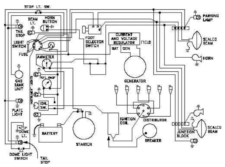
- Identify each of the major elements in the above automotive wiring diagram.
- Explain the purpose and working of any three elements briefly.
- If the total load is 10A from battery, what should be the fuse rating?
- If 500W is the load, what is the voltage and capacity of battery you recommend?
- Identify any two elements which are connected parallel to each other. Why they are connected in parallel?
- Identify any two elements which are connected in series. Why they are connected in series?
Hint- take battery voltage =12V.
====================================================================
Answer
1. Identify each of the major elements in the above automotive wiring diagram.
- Battery
- Starter
- Generator
- Current & Voltage regulator
- Distributer
- Breaker
- Ignition coil
- Junction Block
- Ignition Switch
- Ammeter
- Fuel Gauge
2. Explain the purpose and working of any three elements briefly.
- Battery
An automotive vehicle battery, commonly known as a car battery, is a rechargeable device that provides electrical energy to power the various electrical systems and start the engine of a vehicle. It is typically a lead-acid battery, consisting of several cells connected in series.
The main purpose of an automotive battery is to supply a high burst of electrical current to the starter motor, which initiates the combustion process in the engine. It also powers the vehicle's electrical systems when the engine is not running or when the alternator cannot meet the electrical demands.
Car batteries are designed to deliver a large amount of power for a short period, known as cranking amperage (CA) or cold cranking amperage (CCA), which represents the battery's ability to start the engine in cold temperatures. They are also responsible for stabilizing the vehicle's electrical system and providing power for accessories such as lights, radio, air conditioning, and other electronics.
There are primarily three types of batteries used in automotive applications:
-
Lead-Acid Batteries: Lead-acid batteries have been the most common type of battery used in vehicles for many years. They consist of lead plates submerged in an electrolyte solution of sulfuric acid. These batteries are known for their affordability and ability to deliver high current bursts, making them suitable for starting the engine. However, they have a limited energy density and a relatively short lifespan compared to other types of batteries.
-
Lithium-Ion Batteries: Lithium-ion (Li-ion) batteries have gained significant popularity in the automotive industry, particularly in electric and hybrid vehicles. They offer higher energy density, longer lifespan, and lighter weight compared to lead-acid batteries. Li-ion batteries use lithium-ion intercalation chemistry and typically have cobalt, nickel, manganese, or iron phosphate-based cathodes. They provide more sustained power for longer durations and can be recharged efficiently. However, they are more expensive than lead-acid batteries.
-
Nickel-Metal Hydride (NiMH) Batteries: Nickel-metal hydride batteries have been used in hybrid vehicles, such as early generations of Toyota Prius and Honda Insight. They offer a better energy density than lead-acid batteries but are inferior to Li-ion batteries. NiMH batteries use a hydrogen-absorbing alloy instead of toxic cadmium found in older nickel-cadmium batteries. While they are more environmentally friendly than lead-acid batteries, they have lower power density and shorter lifespan compared to Li-ion batteries.
- Starter
The starter, also known as the starter motor or cranking motor, is an essential component of a vehicle's electrical system. It is responsible for initiating the engine's combustion process by cranking the engine and turning the crankshaft until it starts running on its own.
Here's how the starter works:
-
Ignition Switch: When the driver turns the ignition switch to the "Start" position, it sends an electrical signal to the starter solenoid.
-
Starter Solenoid: The starter solenoid acts as a relay and a switch. It receives the electrical signal from the ignition switch and allows a large electric current to flow from the battery to the starter motor.
-
Starter Motor: The starter motor is an electric motor connected to the engine's flywheel or flexplate. When the electrical current flows through the starter motor, it generates rotational motion.
-
Gear Engagement: The starter motor has a small gear called the pinion gear that meshes with the engine's flywheel or flexplate. As the starter motor spins, the pinion gear engages with the teeth of the flywheel/flexplate.
-
Cranking the Engine: The rotational motion from the starter motor is transmitted to the engine's crankshaft through the engaged flywheel/flexplate. This rotation causes the pistons to move, air-fuel mixture to ignite, and the engine to start running.
-
Release and Disengagement: Once the engine starts running, the ignition system takes over, and the starter motor is disengaged from the flywheel/flexplate. The starter solenoid releases the electrical connection, and the starter motor stops spinning.
The starter requires a significant amount of electrical current to overcome the engine's compression and initiate the combustion process. This is why car batteries are designed to deliver high cranking amperage (CA) or cold cranking amperage (CCA) to power the starter motor effectively.
Overall, the starter plays a crucial role in the starting process of an internal combustion engine, enabling the vehicle to start and run smoothly.
- Generator
In vehicles, the generator refers to the alternator, which is an important component of the electrical system. The alternator serves two primary functions: generating electricity and recharging the vehicle's battery.
Here's how the alternator works:
-
Conversion of Mechanical Energy: The alternator is typically driven by a belt connected to the engine's crankshaft. As the engine runs, it rotates the crankshaft, which, in turn, spins the alternator's rotor.
-
Generation of Alternating Current (AC): The spinning rotor within the alternator creates a changing magnetic field. This magnetic field induces an alternating current (AC) in the stator windings, which are stationary coils of wire surrounding the rotor.
-
Rectification to Direct Current (DC): The AC produced by the alternator is then converted into direct current (DC) using diodes. The diodes act as one-way valves, allowing the current to flow in only one direction.
-
Charging the Battery: The DC output from the alternator is used to supply power to the vehicle's electrical systems and accessories. It also recharges the vehicle's battery, replenishing the electrical energy consumed during engine start-up and powering the vehicle's components when the engine is running.
-
Voltage Regulation: The alternator includes a voltage regulator that monitors the electrical system's voltage and controls the output of the alternator. The voltage regulator ensures that the electrical system operates within a specific voltage range, preventing overcharging or undercharging of the battery.
Unlike the starter motor, which draws a high current for a short period, the alternator operates continuously while the engine is running. It provides electrical power to operate the lights, electronics, heating/cooling systems, and other electrical components of the vehicle. It also maintains the battery's charge, ensuring that it remains in a state of readiness for subsequent engine starts.
In summary, the alternator, often referred to as the generator, plays a crucial role in generating electricity, powering the vehicle's electrical systems, and recharging the battery while the engine is running.
- Distributor
An automotive distributor’s primary function is to send a high-voltage current from the ignition coil to the engine’s spark plugs in the correct firing order. The distributor’s other main job is to control the on-off function of the ignition coil by sending electronic signals to the ignition module.
Automotive manufacturers have replaced distributors in modern vehicles with "distributors" electronic ignition systems. Cars with these systems use individual ignition coils on top of the spark plugs or coil packs with multiple connections. In these vehicles, the engine control unit (ECU) detects the crankshaft's position and sends signals to the ignition coils.
3. If the total load is 10A from battery, what should be the fuse rating?
To determine the appropriate fuse rating for a 10A load from a battery, it is generally recommended to choose a fuse with a rating slightly higher than the maximum expected current to provide a margin of safety. However, it's important to note that specific requirements may vary depending on the application and local electrical codes.
A general rule of thumb is to choose a fuse rating that is around 125% to 150% of the load current. This helps account for any transient current spikes or inrush currents that may occur during startup.
Using this guideline, the fuse rating for a 10A load would be:
Fuse rating = 10A * 1.25 to 1.5 = 12.5A to 15A
Therefore, a suitable fuse rating for a 10A load from the battery would be between 12.5A and 15A. It's important to choose a fuse with the closest available rating above the load current, such as a 15A fuse in this case, to ensure proper protection while allowing for normal operation.
4. If 500W is the load, what is the voltage and capacity of battery you recommend?
Given,
power=500w
battery voltage=12 V.
we take energy=500Wh
The formula for converting wh to Ah is given below
Wh = Ah x V
500=Ah x12
Ah=500/12=41.67.
Battery capacity=41.67Ah
5. Identify any two elements which are connected parallel to each other. Why they are connected in parallel?
In a vehicle wiring circuit, two common elements that are often connected in parallel are the headlights and the taillights. These lights are connected in parallel to ensure that they both receive the necessary voltage and current to operate properly.
Here's why they are connected in parallel:
-
Voltage Distribution: When headlights and taillights are connected in parallel, they are each connected directly to the vehicle's electrical system. This allows them to receive the same voltage as other electrical components in the system. Connecting them in parallel ensures that they operate at the specified voltage, providing optimal lighting performance.
-
Independent Operation: Parallel connections allow the headlights and taillights to function independently of each other. If they were connected in series, the failure of one light bulb could result in the other light bulb not receiving sufficient voltage and consequently not illuminating. By connecting them in parallel, each light has its own individual electrical path, so the failure of one bulb doesn't affect the other.
Additionally, connecting the headlights and taillights in parallel allows them to be controlled separately. This enables features such as turning on only the headlights or taillights depending on the driving conditions, providing flexibility and safety.
It's worth noting that while the headlights and taillights are typically connected in parallel, other elements in a vehicle's wiring circuit may also be connected in parallel, depending on the specific electrical system design and requirements.
6. Identify any two elements which are connected in series. Why they are connected in series?
In a vehicle electrical system, two elements that are often connected in series are the battery and the starter motor. They are connected in series for the following reasons:
-
Voltage Distribution: The battery is the primary power source for the vehicle's electrical system. By connecting the battery and starter motor in series, the starter motor receives the full voltage of the battery. This ensures that the starter motor receives the necessary voltage to crank the engine and start the vehicle.
-
Current Control: Connecting the battery and starter motor in series allows for controlled current flow. The starter motor requires a significant amount of current to operate, and connecting it in series with the battery limits the current flowing through the circuit. This helps prevent excessive current draw, which could potentially damage the starter motor or other components in the system.
-
Sequential Operation: By connecting the battery and starter motor in series, the electrical circuit is designed to enable sequential operation. When the ignition key or button is turned to the "start" position, it completes the circuit, allowing current to flow from the battery through the starter motor. This sequential operation ensures that the starter motor engages and cranks the engine before other electrical components receive power, such as the ignition system, fuel pump, and other accessories.