Project - Analysis of a practical automotive wiring circuit
Project - Analysis of a practical automotive wiring circuit
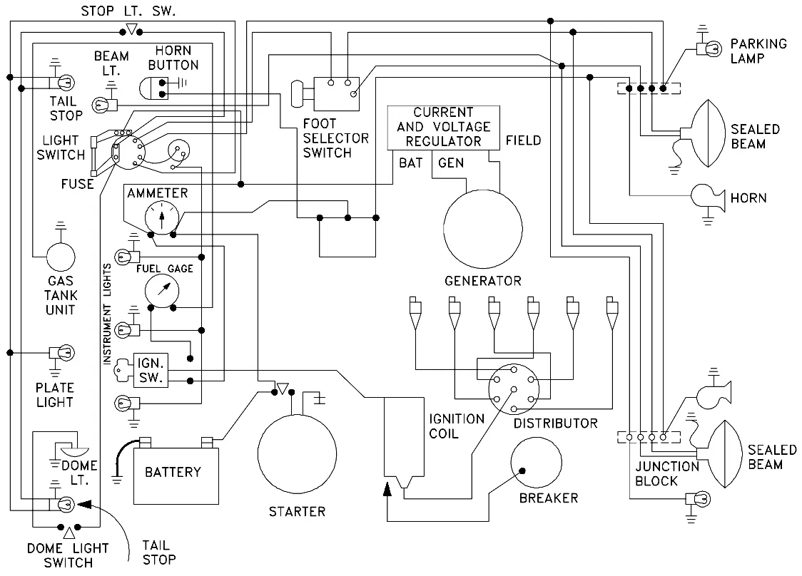
- Identify each of the major elements in the above automotive wiring diagram.
- Explain the purpose and working of any three elements briefly.
- If the total load is 10A from the battery, what should be the fuse rating?
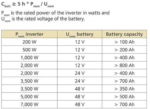
- If 500W is the load, what is the voltage and capacity of the battery you recommend?
- Identify any two elements which are connected parallel to each other. Why they are connected in parallel?
- Identify any two elements which are connected in series. Why they are connected in series?
Identify each of the major elements in the above automotive wiring diagram:
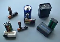
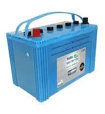
- Battery
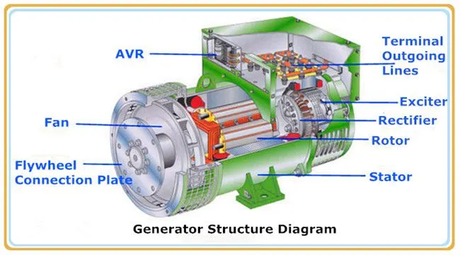
- Generator
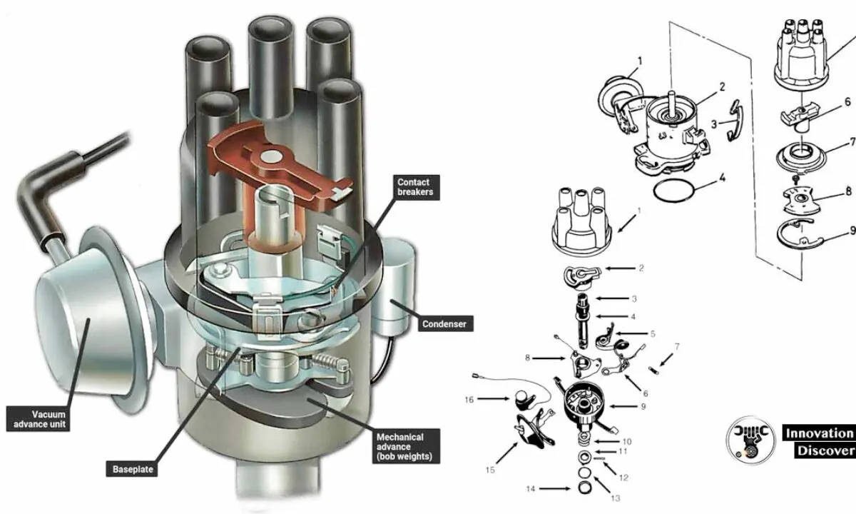
- Distributor
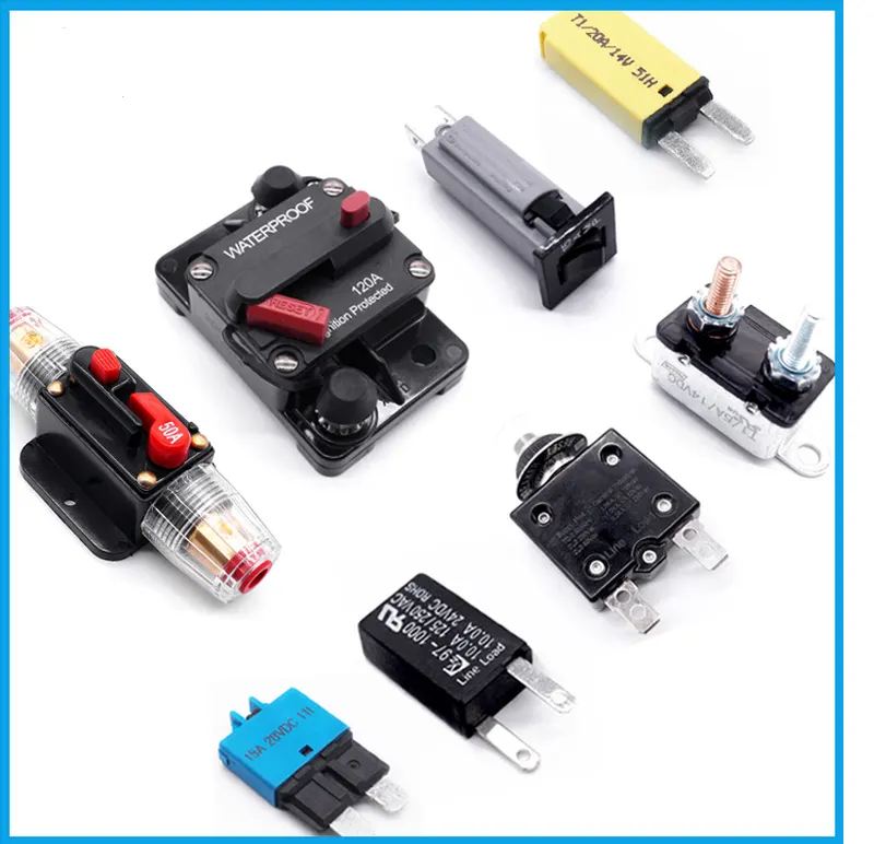
- Breaker
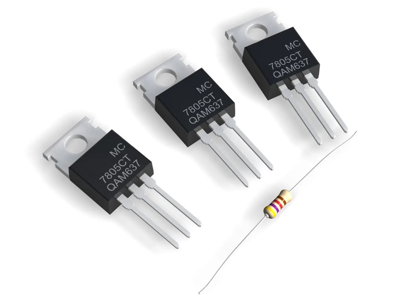
- current and voltage regulator
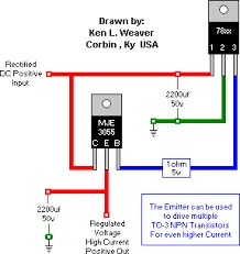
- Junction block
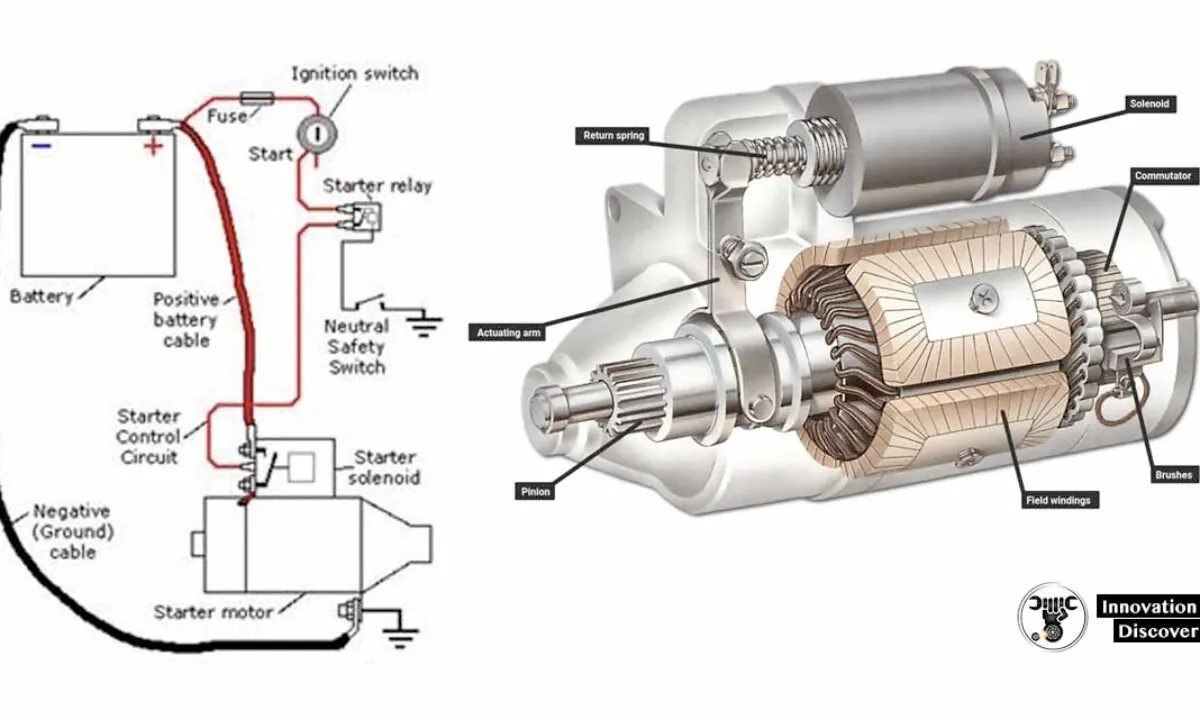
- starter
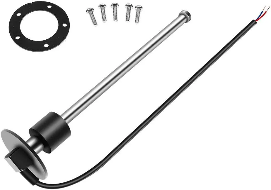
- Gas tank unit
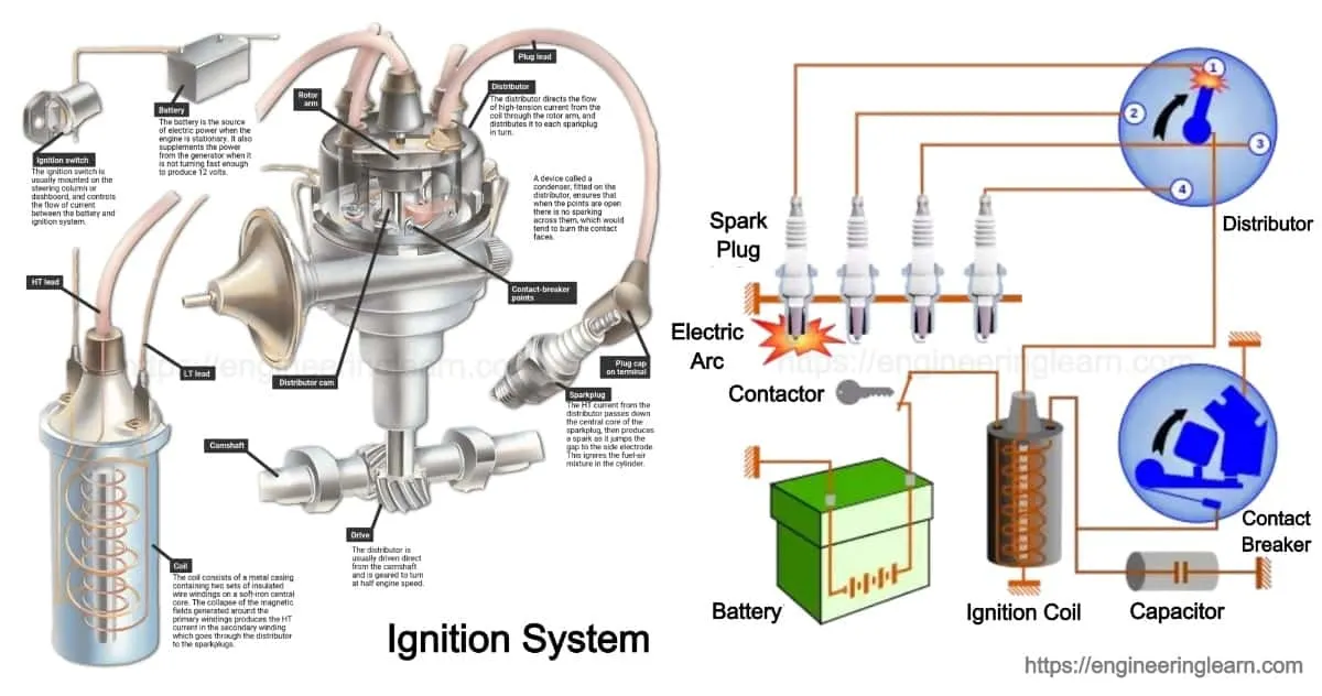
- Ignition coil
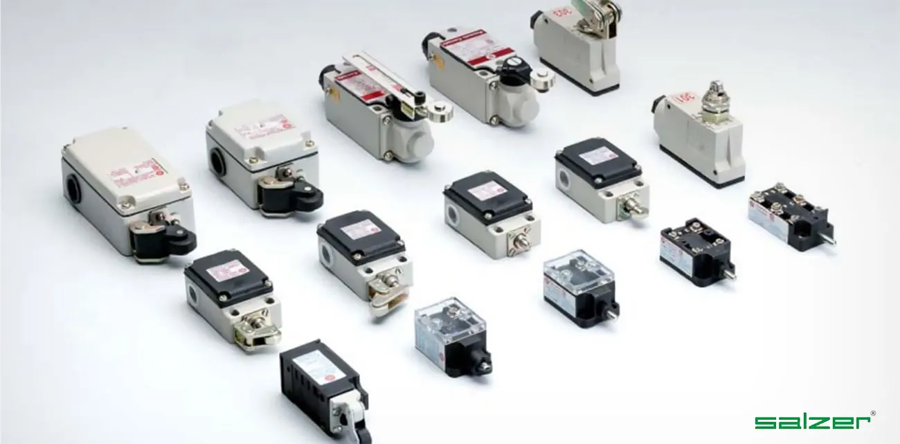
- Foot selector switch
- fuse
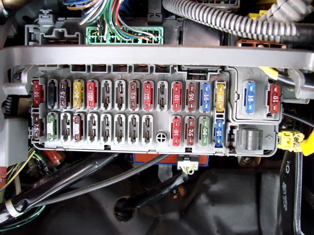
- Ammeter
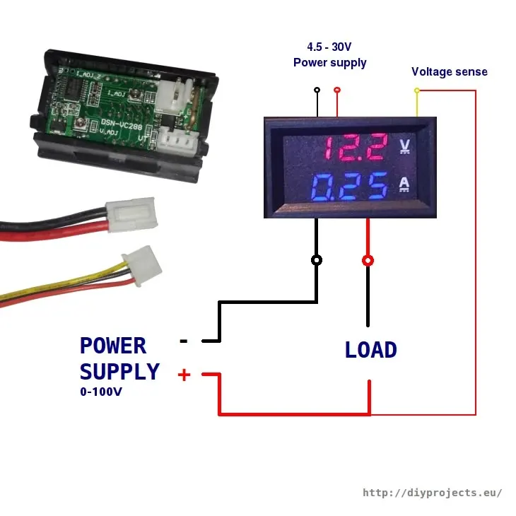
- Dome light switch
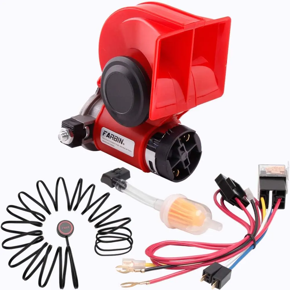
- Horn Button
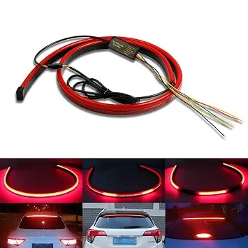
- Tail stop
- light switch
Explain the purpose and working of any three elements briefly.
Answer:
1. Distributer:
The purpose of the ignition system is to generate a very high voltage from the car's 12-volt battery, and to send this to each sparkplug in turn, igniting the fuel-air mixture in the engine's combustion chambers.
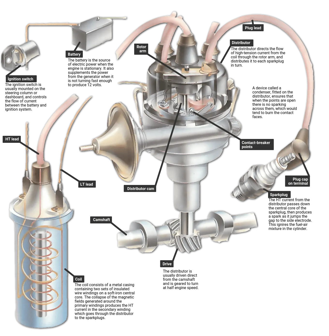
The coil is the component that produces this high voltage. It is an electromagnetic device that converts the low-tension (LT) current from the battery to the high-tension (HT) current each time the distributor contact-breaker points open.
The distributor unit consists of a metal bowl containing a central shaft, which is usually driven directly by the camshaft or, sometimes, by the crankshaft.
The bowl houses the contact-breaker points, rotor arm, and a device for altering the ignition timing. It also carries the distributor cap.
Distributing the current
The distributor cap is made of nonconductive plastic, and the current is fed to its central electrode by the HT lead from the center of the coil.
Inside the cap, there are more electrodes often called segments to which the sparkplug leads are connected, one per cylinder.
The rotor arm is fitted on top of the central shaft and connects to the central electrode by means of a metal spring or spring-loaded brush on the top of the distributor cap.
The current enters the cap through the central electrode, passes to the center of the rotor arm through the brush, and is distributed to each plug as the rotor arm revolves.
As the rotor arm approaches a segment, the contact-breaker points open and HT current passes through the rotor arm to the appropriate sparkplug lead.
The contact-breaker points are mounted inside the distributor. They act as a switch, in synchronization with the engine, that cuts off and reconnects the 12-volt low-tension (LT) circuit to the coil.
The points are opened by cams on the central shaft and are closed again by a spring arm on the moving contact.
With the points closed, LT current flows from the battery to the primary windings in the coil, and then to earth through the points.
When the points open, the magnetic field in the primary winding collapses, and a high-tension (HT) current is induced in the secondary windings.
This current is transferred to the sparkplugs through the distributor cap.
On a four-cylinder engine, there are four cams. With each full rotation of the shaft the points open four times. Six-cylinder engines have six cams and six electrodes in the cap.
The position of the points and the distributor's body in relation to the central shaft can be adjusted manually.
This alters the timing of the spark to obtain an exact setting.
Further changes occur automatically as the engine speed varies according to the throttle opening.
In some modern ignition systems, micro-electronics ensure the optimum ignition timing for all engine speeds and engine load conditions.
2. Ignition System:
In an internal combustion engine, the electronic ignition system is used to ignite air fuel. Basically, this provides heat in form of a spark for ignition. This system works inside the engine for creating a spark in the spark plug.
Why do we need an Electronic ignition system:
There are already three different types of ignition systems Battery ignition system, Glow plug ignition system, and Magneto Ignition system.
It is because there are certain limitations in all the given ignition systems, for example, If we are talking about the Glow plug ignition system then this system electrode was used because that combustion was uncontrolled.
Because of that, the exhaust emission rate was very high and there was also some limitation in the battery and the magneto ignition system which is replaced by another system and the best one was the electronic ignition system. This provides high performance, better mileage, and reliability to this system.
To replace all the other ignition systems, an electronic ignition system is introduced in the market and it replaced all other.
When we are talking about the magneto ignition system, the electrode is replaced by a spark because that emission rate decreases but the magneto system depends upon the speed of the vehicle, and vehicle speed can never be constant on road because of traffic and many other situations, which is not fulfilling the need.
That’s why the battery ignition system is introduced. Even today in most vehicles, a battery ignition system is used because it has high accuracy and high efficiency.
But there are certain limitations with the high-speed engine as it is less efficient, and because of that, the electronic ignition system is introduced which fulfills all the requirements for an efficient engine. Parts or Construction of Electronic Ignition System:
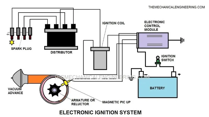
The electronic Ignition System consists of the following main Parts:
- Battery
- Ignition Switch
- Electronic control module
- Ignition coil
- Ignition distributor and
- Spark plug
Battery:
It works as a powerhouse of the whole system and the energy which is necessary for the working of the whole system is provided by the battery.
A lead-acid battery is used in this system to provide electrical energy. This battery is rechargeable and it gets recharged through the dynamo through the engine.
Ignition switch:
This is the main switch of the whole system. You can on/off with this switch. The negative side is grounded and the positive side is connected to the primary winding of the coil.
Electronic control module:
A control module is the brain of an electronic ignition system. All the instructions are already programmed in this module and it also controls or monitors the timing and intensity of the spark.
This is one of the important parts of the whole system. The whole system is controlled by an electronic control module.
Armature:
This consists of the reluctor which is the rotating part of the armature which consists of the tooth. To make or break the circuit armature takes a regular supply of voltage through the electronic control module.
When the armature tooth comes in contact with the pickup coil, voltage is generated and it stops the flow of current from the primary circuit.
Ignition coil:
It consists of the primary winding and the secondary winding. This produces high voltage for the spark plug. The coil is having a soft iron core.
Both the end of the primary winding is connected with exterior terminals. The primary winding is having 200-300 turns but the secondary consists of 21000 turns and another end is connected with high tension wire.
Ignition distributor:
Distributor helps to distribute current for spark plug when there is the use of multi-cylinder or more than one then sparks plug is used. It consists of the metallic electrode on the periphery and the rotor in the middle of it.
The metallic electrodes are connected with spark plugs also known as ignition harnesses. The rotor is connected with the secondary winding, which is driven by the camshaft.
When the rotor starts rotating, it passes high tension current to the ignition harness which is carried by high tension currents with spark plugs.
Spark plug:
The plug emits sparks for the Ignition of fuel. It has two wires first one is connected with a high-tension current-carrying wire and the other one is grounded, because of the potential difference it creates sparks and combustion takes place.
Electronic Ignition System Working Principle:
When the driver inserts the key into his car for switching on the ignition switch, just after that battery starts and supplies current to the system.
Current passes through the ignition switch and moves toward the ignition coil on the system then start passing through the primary winding of the coil.
As the current passes through the primary coil, the pick-up coil got activated which is in the armature. It receives current as a voltage on the pick-up. Just after receiving voltage, the reluctor starts rotating which consists of the tooth.
When the tooth comes in front of the pick-up coil exactly at the same time the pick-up coil starts sending a signal to the electronic control module.
After receiving a voltage signal, it stops the current supply from the battery up to the primary coil. When the tooth deviates from the point, it senses the change in voltage, and then again it sends a signal of change in voltage to the electronic control module.
We all know that the electronic control system is already a programmed system, so exactly after sending a signal of change in voltage it again starts supplying the current in the primary winding.
Because of this continuous make and break of the current circuit, it creates a magnetic field inside the ignition coil because of that, the secondary winding emf is induced.
This emf increases voltage up to 50000 V. The voltage is supplied to the distributor.
It consists of a rotating rotor and distributor points, which are programmed as per the ignition. When there is a jump of voltage between the air gap of the rotator and the distributor of high voltage, after that it reaches to spark plug through high tension wire.
Spark is generated because of the voltage difference between the central electrode and the ground electrode because combustion is possible in air-fuel.
Application of Electronic Ignition System:
The electronic ignition system has a lot of applications in the 21st century.
- It is mostly used in modern hypercars.
- It is mostly used in Audi, Mahindra XUV, KTM bikes, Ducati, and many more.
- It is also used in aircraft engines.
Advantages of Electronic Ignition System:
The following advantages of the Electronic Ignition System include:
- These are low maintenance systems as compared to others like Battery Ignition System, the Glow plug ignition system, and Magneto Ignition System.
- It has no moving parts because it is controlled by the electronic control unit(ECV).
- Emission is less as compared to other means because this system is environmentally friendly.
- It increases the efficiency of the engine and also it is fuel-efficient.
- It is more accurate compared to the magneto system.
- The vehicles having this system have a long life and are also reliable.
Disadvantages of Electronic Ignition System:
The main disadvantage of electronic Ignition is that this system is very expensive because all cannot afford the vehicles having an electronic ignition system.
3. Battery Ignition System Definition:
A battery ignition system is used in the SI engine for supplying the power to the spark plug for the generation of spark to burn the air-fuel mixture in the SI Engine system.
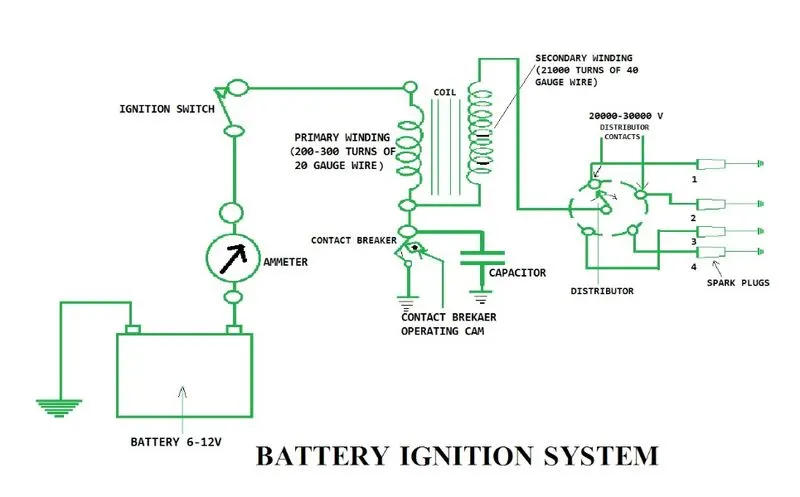
The battery Ignition System consists of the following Main Parts:
- Battery
- Ballast Resistor
- Ammeter
- Ignition Switch
- Primary Winding
- Contact Breaker
- Capacitor
- Secondary Winding
- Distributor
- Spark Plug
Battery:
The battery is used here is a rechargeable lead-acid battery. It stores electrical energy and is used to provide electricity for ignition. The battery is charged by the dynamo which is driven by the engine. The battery is connected to the Ignition switch.
Ballast Resistor:
The ballast resistor controls the current that passes through the primary winding.
It is made up of Iron and Iron has the property to increase electrical resistance rapidly by an increase in temperature at a certain limit. This additional resistance resists the flowing current which controls the temperature of the ignition coil.
It helps to maintain the temperature under the prolonged condition and Here It is connected in series with primary winding to regulate the current in the primary winding.
Ammeter:
It is a measuring instrument used for measuring the current.
Ignition Switch:
It is an important part of the system. It is used for ON and OFF the system.
Ignition Coil:
An ignition coil is the main part of the battery ignition system which is used to step the voltage which means low to high and that is used for the generation of spark in the spark plug.
Ignition Coil consists of a magnetic core or soft wire, and two electrical winding called primary and secondary winding.
Primary Winding:
The primary winding has 200-300 turns. The current which is flowing through the primary winding creates a magnetic field.
Secondary Winding:
The secondary winding has 21000 turns of 40 gauge wire. It is insulated to withstand high voltage. As you can see in the diagram one end is connected to the PW and the other ends to the distributor.
Contact Breaker:
The name itself indicates ‘contact breaker’ it means adding and breaking the primary circuit to the ignition coil.
The function of the contact breaker is current flows in an ignition coil when it is closed and flows stop when it is open. In the above diagram, you can see it’s close.
Capacitor:
It is similar to an electric capacitor. Generally, It stores electrical energy in an electric field. In capacitor two metal plates are separated from each other through the air which is an insulating material.
The main function of the capacitor is to prevent the arc from across the breaker point and if it is not connected to the primary circuit the induced voltage would cause an arc across the breaker point and that is very dangerous.
Distributor:
The distributor also plays a vital role in this system. It provides ignition pulses to the individual spark plug-in sequences at the correct time.
There are 2 different types of distributors.
- Brush Type and
- Gap Type
Spark Plug:
As you can see in the diagram each Spark plug is connected to the distributor. The spark plug is used for injecting the spark and which causes the start burning of the air-fuel mixture in the system. Spark plug used in SI Engine.
Battery Ignition System Working Principle:
When the ignition switch is turned ON, the primary circuit gets closed and the current starts flowing through it. This current sets up the magnetic field around the soft iron core of the coil.
The current starts flowing through the condenser when the breaker points open, and when it closes the current is flowing through the contact breaker.
When the current passes through the condenser, the condenser charges, the primary current falls, and the magnetic field gets collapses.
This change in the magnetic field induces a current in the primary winding that flows in the same direction as the primary current.
And charges the condenser voltage to much higher than the battery voltage thus stopping the current flowing from the battery.
Due to these processes, the condenser gets discharged into the battery. Now reverse the direction of the primary current and the magnetic field induces a high voltage in the secondary winding.
Now the high voltage sends to the distributor by the high tension wire. Between the distributor and spark plug, an ignition harness is connected as you can see in the diagram.
Now the current passes to the spark plug one by one and it will produce a spark for the burning of an air-fuel mixture
Battery Ignition System Advantages:
The main advantages of a Battery System are:
- The battery System gives more power output.
- Fuel efficiency is also good.
- There are no moving parts here.
- Better combustion because in other convention systems only 70 to 75 percent of the air-fuel mixture gets burned but here more than 90 percent gets burned.
- Spark intensity is also good.
Battery Ignition System Disadvantages:
It is having some disadvantages too and those are:
- Battery Ignition takes more space compared to other electronic ignition systems.
- The battery is essential for generating the spark when the battery is discharged it won’t start.
- It won’t produce a spark when the spark plug is fouled.
- More Maintenance because of Arcing, Pitting of contact breaker point.
Battery Ignition System Application:
The following application of the Battery Ignition System:
- Firstly Battery System is used in SI Engine for producing the spark to the spark plug.
- It is also used in light commercial and Modern vehicles which are having SI engines.
fuse:
Fuse is a self-destructive protection device that is widely used in electrical and electronic circuits. There are different types of fuses available in the market and they are cartridge fuses, automotive fuses, resettable fuses / polyfuse, semiconductor fuses, overvoltage suppression, high voltage fuses, Rewireable fuses, Striker fuse, Switch fuse, HRC (High Rupture Current) fuses, etc.
Fuse rating calculation is an important factor in the electrical system design and installation. Also, if you are looking to find the exact status of your electrical installation, then you can get the Electrical Installation Condition Report quotes from Energy North Ltd.
Some Fuse terminology to be remembered:
- Fuse sizing: Nearest size available with respect to rating
- Fuse rating: Exact duty of the fuse.
Fuse rating for electronics circuit = 1.10 x PW / x V(V)
Formula to Calculate the Fuse Rating:
There is a simple and basic formula for working out the fuse rating, voltage, or wattage for each appliance:
P=VxI
Where,
P for power in Watts;
V for voltage in volt;
I for current in Amps.
The fuse rating can be calculated by dividing the power used by the appliance by the voltage going into the appliance.
I (Amps) = P (Watts) /V (Voltage)
Assumed,
case1:fuse rating = wattage/voltage
= 1000/230
= 4.35A
case2:fuse rating = wattage/voltage
= 2000/230
= 8.69A
Therefore the sutable for fuse rating 10A.
If 500W is the load, what is the voltage and capacity of the battery you recommend?
Answer:
General recommendations for alternating current and hybrid systems:
In contrast to so-called square wave or trapezoidal inverters (grey square curve), Steca sine wave inverters produce a real and precisely controlled sine wave (red sine wave) at their output. The sine wave inverters assure that all loads which are suitable for grid operation can also be operated on a solar home system without any problems. Furthermore, they offer the advantage that no significant noises are produced in the inverter and there is no loud background noise to be heard on a connected radio, for example.
Selecting an inverter:
The power of the inverter must be selected according to the way it will be used. The sum of the power of all loads must not exceed the rated power of the inverter. The maximum power of the inverter must be able to cover the starting currents of the loads. In order to allow the connection of more loads, KATEK Memmingen recommends over-dimensioning the inverter.
Selecting the PV generator and solar charge controller:
The solar module array has to be adjusted to the local sunlight conditions and the system‘s energy requirement. In order to avoid stagnation times, the PV generator must also provide enough power during months with little solar radiation in order to cover the requirement of the connected loads. The chosen solar charge controller must also be suitable for the maximum short-circuit current of the PV generator and the maximum load current. In some applications, however, technical properties also play an important role in the choice of solar charge controllers. This may mean that a high-performance solar charge controller with corresponding additional functions is used in a system with a low output. In order to keep the initial investment small, we recommend planning the size of the PV generator and battery according to the current energy consumption and choosing a solar charge controller which will allow the system to be expanded later.
Selecting the battery:
In order to also be able to supply loads with high requirements without any problems, the size of the battery must be chosen with care. Some critical loads such as fridges, freezers, pumps, and motors need extremely high starting currents in their start-up phases. In order to be able to power such loads, it is important to use a high-performance inverter with a high overload capacity, particularly in the start-up phase. The battery must also possess a large enough capacity so that sufficient currents are made available to the inverter in the start-up phase. We recommend choosing the battery size according to the following formula: the battery capacity should be at least five times as large as the rated power of the inverter divided by the rated voltage of the battery.
Selecting the system voltage:
The power requirement of the loads should be the decisive factor when choosing the system voltage. The higher the power, the higher the system voltage. If no 12 V DC loads are connected to the system, a higher system voltage of 24 V or 48 V should be chosen in order to reduce the alternating currents, and thus the losses on the DC side. Inverters also generally work more effectively with a higher input voltage. All in all, a higher system voltage leads to the system having a greater efficiency, since losses are reduced.
Cable lengths and cross-sections:
Direct currents in inverter systems are typically large. For this reason, it is important to dimension the cables between the battery and the inverter appropriately. Always connect the inverter directly to the battery. The cable you use should be as short as possible. In addition, the cable cross-section should match the expected flow of current. In case of doubt, a thicker cable should be chosen. This can have a significant influence on the overall behavior of the system. Using thick and short cables can limit losses and thus allow you to create a system with a better level of efficiency and/or better performance. If the cables on the direct current side of the inverter are included in the delivery, these should not be lengthened, and a smaller cross-section should not be used.
Identify any two elements which are connected parallel to each other. Why they are connected in parallel:
Answer:
parallel connection :
- Dome light and Tail stop are parallel connections.
There is a branching location in the circuit that allows for more than one pathway by which charge can flow through the external circuit.
I can see the wiring of the diagram dome light and Tail stop in a parallel connection.
Identify any two elements which are connected in series. Why they are connected in series
Answer:
series connection :
- fuse gauge and ammeter are series connections.
There is no branching in the circuit - that is, no location where one wire leads into a point and branches off into two or more wires at that particular point.
I can see the wiring of the diagram fuse gauge and ammeter are series connections.