Project 2 - Rankine cycle Simulator
Rankine cycle Simulator
AIM:
- Creation of Rankine cycle simulator from a given input and reading the data from a standard thermodynamic library of steam table.
OBJECTIVE:
- To create a Rankine Cycle simulator in MATLAB.
- To calculate the state point using function XStream.
- To plot the T-S and H-S curve for a given input in Rankine Cycle.
- To get output in the command window for each state point in the cycle.
Description:
The Rankine cycle is one of the vapor-powered cycles. This cycle is somewhat different from than gas-powered cycle in which the working fluid remained gas throughout the entire cycle. In vapor powered cycle the working fluid is steam because of its many desirable characteristics such as low cost of production, availability, and high enthalpy of vaporization. There are many impracticalities associated with the Carnot cycle which can be eliminated by superheating the steam and condensing it in the condenser which makes it best for nuclear power plants and other steam-related power generation sources.
The process in the Rankine cycle is given as:
- Isentropic Compression in Pump.
- Constant pressure heat addition in the boiler.
- Isentropic expansion in a turbine.
- Constant pressure heat rejection in the condenser.
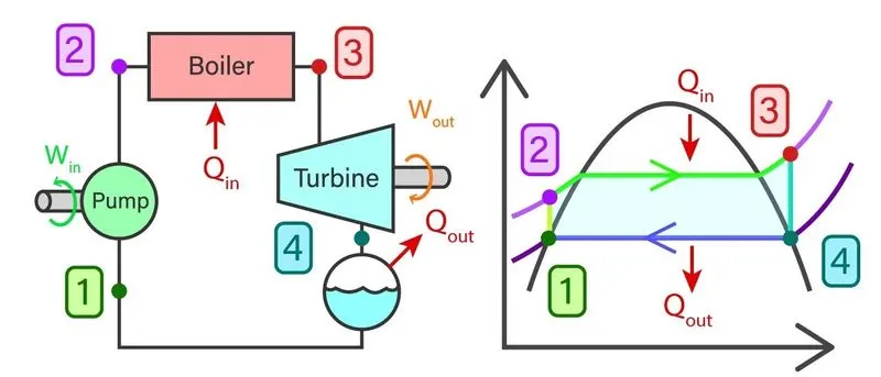
Water enters the pump at state I as saturated liquid and is compressed isentropically to the operating pressure of the boiler. The water temperature increases somewhat during this isentropic compression process due to a slight decrease in the specific volume of water. The vertical distance between states 1 and 2 on the T-s diagram is greatly exaggerated for clarity
Water enters the boiler as a compressed liquid at state 2 and leaves as superheated vapor at state 3. The boiler is basically a large heat exchanger where the heat originating from combustion gases, nuclear reactors, or other sources is transferred to the water essentially at constant pressure. The boiler, together with the section where the steam is superheated (the superheater), is often called the steam generator.
The superheated vapor at state 3 enters the turbine, where it expands isentropically and produces work by rotating the shaft connected to an electric generator. The pressure and the temperature of steam drop during this process to the values at state 4, where steam enters the condenser. At this stage, steam is usually a saturated liquid-vapor mixture with high quality. Steam is condensed at constant pressure in the condenser, which is basically a large heat exchanger, by rejecting heat to a cooling medium such as a lake, a river, or the atmosphere. Steam leaves the condenser as saturated liquid and enters the pump, completing the cycle. In areas where water is precious, the power plants are cooled by air instead of water. This cooling method, which is also used in car engines, is called dry cooling.
Remembering that the area under the process curve on a T-s diagram represents the heat transfer for internally reversible processes, we see that the area under process curves 2-3 represents the heat transferred to the water in the boiler, and the area under the process curve 4-1 represents the heat rejected in the condenser. The difference between these two is the network produced during the cycle.
All the four components of the Rankine cycle are steady flow devices hence the process regarding this device can be evaluated as the steady-state process. The steady-state flow energy equation per unit mass of steam reduces to:
(qIn - qout) + (WIn - Wout) = he - hi
The boiler and condenser are not involved in any mechanical work whereas the pump and turbine are assumed to be isentropic in nature while working throughout the cycle, then conservation of energy relation for each device can be expressed as:
Wpump = h2 - h1
Where,
h1 = hfatP1 and v1 = vfat P1
The heat added to the boiler can be given as
qIn = h3 - h2
The work which can be taken out of cycle from the turbine is given as:
Wout = h3 - h4
The heat removed from the condenser is given as:
qout = h4 - h1
The thermal efficiency of the Rankine cycle is given as:
nth = (WNet/qIn) = 1 - (qout/qIn)
Where,
WNet = qIn - qout = Wturb - Wpump
PROGRAM:
The code for Rankine Cycle Simulator:
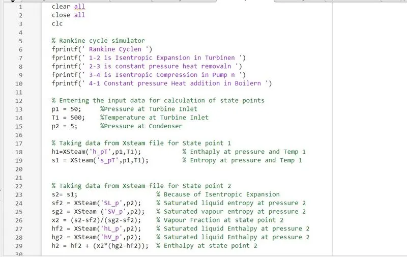
clear all
close all
clc
% Rankine cycle simulator
fprintf('Rankine Cyclen')
fprintf('1-2 is Isentropic Expansion in Turbinen')
fprintf('2-3 is constant pressure heat removaln')
fprintf('3-4 is Isentropic Compression in Pump n')
fprintf('4-1 Constant pressure Heat addition in Boilern')
% Entering the input data for calculation of state points
p1 = 50; %Pressure at Turbine Inlet
T1 = 500; %Temperature at Turbine Inlet
p2 = 5; %Pressure at Condenser
% Taking data from Xsteam file for State point 1
h1=XSteam('h_pT',p1,T1); % Enthaply at pressure and Temp 1
s1 = XSteam('s_pT',p1,T1); % Entropy at pressure and Temp 1
% Taking data from Xsteam file for State point 2
s2= s1; % Because of Isentropic Expansion
sf2 = XSteam('SL_p',p2); % Saturated liquid entropy at pressure 2
sg2 = XSteam ('SV_p',p2); % Saturated vapour entropy at pressure 2
x2 = (s2-sf2)/(sg2-sf2); % Vapour Fraction at state point 2
hf2 = XSteam('hL_p',p2); % Saturated liquid Enthalpy at pressure 2
hg2 = XSteam('hV_p',p2); % Saturated liquid Enthalpy at pressure 2
h2 = hf2 + (x2*(hg2-hf2)); % Enthalpy at state point 2
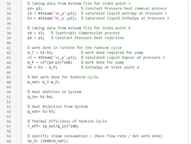
% Taking data from Xsteam file for state point 3
p3= p2; % Constant Pressure heat removal process
s3 = XSteam('sL_p',p3); % Saturated liquid entropy at Pressure 3
h3 = XSteam('hL_p',p3); % Saturated liquid Enthalpy at Pressure 3
% Taking data from Xsteam file for State point 4
s4 = s3; % Isentropic Compression process
p4 = p1; % Constant Pressure heat rejection
% work done in Turbine for the Rankine cycle
W_T = h1-h2; % work done required for pump
v3 = XSteam('vL_p',p3); % Saturated Liquid Vapour at pressure 3
W_P = v3*(p4-p3)*100; % Work done for pump
h4 = h3 - W_P; % Enthalpy at State point 4
% Network done for Rankine Cycle
W_net= W_T-W_P;
% Heat Addition to System
Q_in= h1-h4;
% Heat Rejection from System
Q_out= h2-h3;
% Thermal Efficiency of Rankine Cycle
T_eff= (W_net/Q_in)*100;
% specific steam consumption = (Mass flow rate / Net work done)
Sp_S= (3600/W_net);
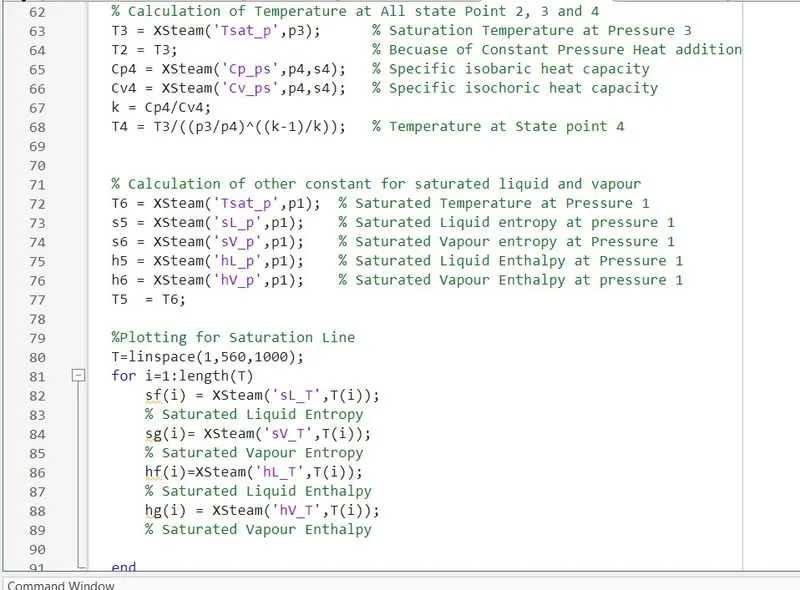
% Calculation of Temperature at All state Point 2, 3 and 4
T3 = XSteam('Tsat_p',p3); % Saturation Temperature at Pressure 3
T2 = T3; % Becuase of Constant Pressure Heat addition
Cp4 = XSteam('Cp_ps',p4,s4); % Specific isobaric heat capacity
Cv4 = XSteam('Cv_ps',p4,s4); % Specific isochoric heat capacity
k = Cp4/Cv4;
T4 = T3/((p3/p4)^((k-1)/k)); % Temperature at State point 4
% Calculation of other constant for saturated liquid and vapour
T6 = XSteam('Tsat_p',p1); % Saturated Temperature at Pressure 1
s5 = XSteam('sL_p',p1); % Saturated Liquid entropy at pressure 1
s6 = XSteam('sV_p',p1); % Saturated Vapour entropy at Pressure 1
h5 = XSteam('hL_p',p1); % Saturated Liquid Enthalpy at Pressure 1
h6 = XSteam('hV_p',p1); % Saturated Vapour Enthalpy at pressure 1
T5 = T6;
%Plotting for Saturation Line
T=linspace(1,560,1000);
for i=1:length(T)
sf(i) = XSteam('sL_T',T(i));
% Saturated Liquid Entropy
sg(i)= XSteam('sV_T',T(i));
% Saturated Vapour Entropy
hf(i)=XSteam('hL_T',T(i));
% Saturated Liquid Enthalpy
hg(i) = XSteam('hV_T',T(i));
% Saturated Vapour Enthalpy
end
% Plotting T-S Diagram for Rankine Cycle
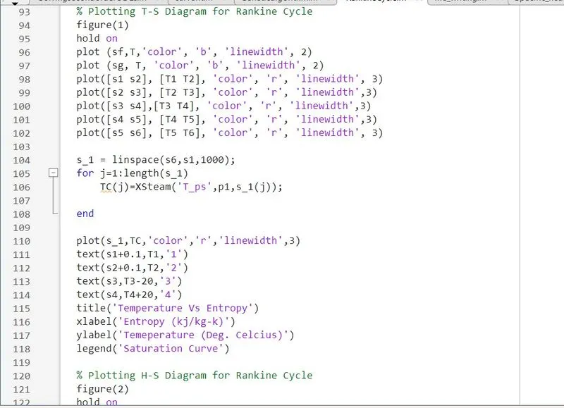
figure(1)
hold on
plot (sf,T,'color', 'b', 'linewidth', 2)
plot (sg, T, 'color', 'b', 'linewidth', 2)
plot([s1 s2], [T1 T2], 'color', 'r', 'linewidth', 3)
plot([s2 s3], [T2 T3], 'color', 'r', 'linewidth',3)
plot([s3 s4],[T3 T4], 'color', 'r', 'linewidth',3)
plot([s4 s5], [T4 T5], 'color', 'r', 'linewidth',3)
plot([s5 s6], [T5 T6], 'color', 'r', 'linewidth', 3)
s_1 = linspace(s6,s1,1000);
for j=1:length(s_1)
TC(j)=XSteam('T_ps',p1,s_1(j));
end
plot(s_1,TC,'color','r','linewidth',3)
text(s1+0.1,T1,'1')
text(s2+0.1,T2,'2')
text(s3,T3-20,'3')
text(s4,T4+20,'4')
title('Temperature Vs Entropy')
xlabel('Entropy (kj/kg-k)')
ylabel('Temeperature (Deg. Celcius)')
legend('Saturation Curve')
% Plotting H-S Diagram for Rankine Cycle
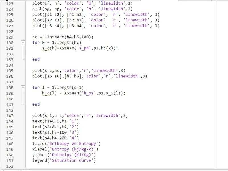
figure(2)
hold on
plot(sf, hf, 'color', 'b', 'linewidth',2)
plot(sg, hg, 'color', 'b', 'linewidth',2)
plot([s1 s2], [h1 h2], 'color', 'r', 'linewidth', 3)
plot([s2 s3], [h2 h3], 'color', 'r', 'linewidth', 3)
plot([s3 s4], [h3 h4], 'color', 'r', 'linewidth', 3)
hc = linspace(h4,h5,100);
for k = 1:length(hc)
s_c(k)=XSteam('s_ph',p1,hc(k));
end
plot(s_c,hc,'color','r','linewidth',3)
plot([s5 s6],[h5 h6],'color','r','linewidth',3)
for l = 1:length(s_1)
h_c(l) = XSteam('h_ps',p1,s_1(l));
end
plot(s_1,h_c,'color','r','linewidth',3)
text(s1+0.1,h1,'1')
text(s2+0.1,h2,'2')
text(s3,h3-100,'3')
text(s4,h4+200,'4')
title('Enthalpy Vs Entropy')
xlabel('Entropy (kj/kg-k)')
ylabel('Enthalpy (KJ/Kg)')
legend('Saturation Curve')
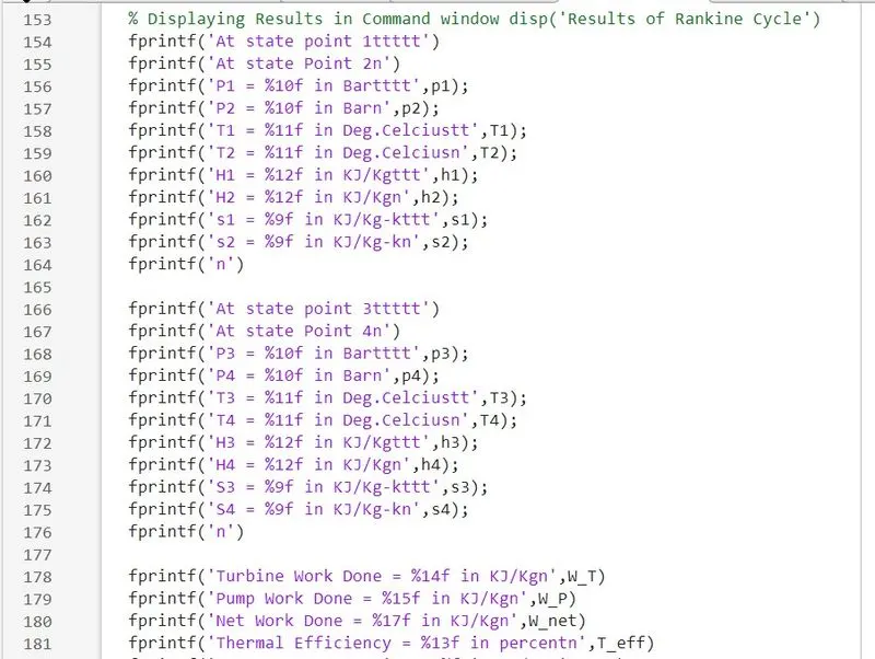
% Displaying Results in Command window disp('Results of Rankine Cycle')
fprintf('At state point 1ttttt')
fprintf('At state Point 2n')
fprintf('P1 = %10f in Bartttt',p1);
fprintf('P2 = %10f in Barn',p2);
fprintf('T1 = %11f in Deg.Celciustt',T1);
fprintf('T2 = %11f in Deg.Celciusn',T2);
fprintf('H1 = %12f in KJ/Kgttt',h1);
fprintf('H2 = %12f in KJ/Kgn',h2);
fprintf('s1 = %9f in KJ/Kg-kttt',s1);
fprintf('s2 = %9f in KJ/Kg-kn',s2);
fprintf('n')
fprintf('At state point 3ttttt')
fprintf('At state Point 4n')
fprintf('P3 = %10f in Bartttt',p3);
fprintf('P4 = %10f in Barn',p4);
fprintf('T3 = %11f in Deg.Celciustt',T3);
fprintf('T4 = %11f in Deg.Celciusn',T4);
fprintf('H3 = %12f in KJ/Kgttt',h3);
fprintf('H4 = %12f in KJ/Kgn',h4);
fprintf('S3 = %9f in KJ/Kg-kttt',s3);
fprintf('S4 = %9f in KJ/Kg-kn',s4);
fprintf('n')
fprintf('Turbine Work Done = %14f in KJ/Kgn',W_T)
fprintf('Pump Work Done = %15f in KJ/Kgn',W_P)
fprintf('Net Work Done = %17f in KJ/Kgn',W_net)
fprintf('Thermal Efficiency = %13f in percentn',T_eff)
fprintf('Sp.Steam Consumption = %f in KJ/Kwn',Sp_S)
EXPLANATION FOR CODE:
- The creation of the Rankine cycle simulator starts with some input values which are required to calculate the other state point in the cycle eventually.
- The Rankine cycle process is displayed in the command window and then inputs are entered which are inlet pressure for the turbine, the temperature at the turbine inlet, and pressure at the condenser.
- Then we are using the XStream function file for reading state points. First, we get the value of enthalpy and entropy at state point 1 from the XStream function file.
- As process from 1-2 is isentropic compression the entropy at point 1 is equal to point 2. The term '(s_pT, p1, T1)' refers to entropy at pressure and temperature point 1.
- The term 'sg' and 'st' is referred to saturated liquid and saturated vapor entropy respectively. This value is used to calculate other functions according to mathematical relations.
- Similarly, other points are taken from the XStream function file which is necessary to calculate other parameters. After that work done in the turbine and pump is calculated for further getting the network done Rankine cycle.
- After calculating the net work done the efficiency of the Rankine cycle is calculated along with specific steam consumption which is steam consumed by a locomotive cylinder per unit of output of work done.
- Then temperature at each point of the cycle is calculated using input taken from the start of the program and data taken from the XStream file. Forgiven temperature ranges from lower to higher entropy points are calculated to create the T-S plot. Similarly, another for loop is used to generate the saturation curve in each plot.
- Then plotting is done respectively for T-s and H-s graph in the Rankine cycle and each state point value has been put in the command window.
RESULT:
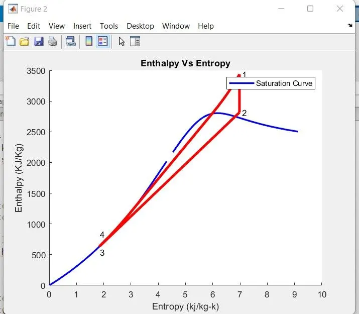
To make the graph more deliberate, we are changing some values in the inputs by increasing the inlet pressure and temperature along with condenser pressure, which results in the following graphs.
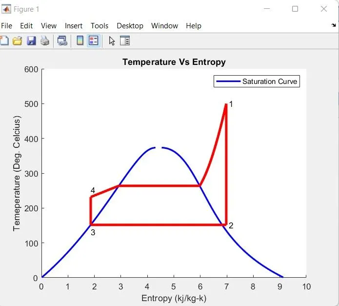
From the above diagram as we can see along with the saturation curve point I start with a turbine from which heat rejection is started which is again an isentropic process. The steam is get cooled in the condenser and in form of saturated liquid as it is under the curve. Then it was pumped to enter the boiler where its temperature is increased to change it from saturated liquid to saturated vapor form.
The values for the state point in command windows are given as:
- For Inlet pressure in Turbine as = 50 bar.
- Inlet temperature in Turbine = 500 deg.cel.
- Pressure in condenser = 5 bar.
Rankine Cycle:
1-2 is Isentropic Expansion in Turbine
2-3 is constant pressure heat removal
3-4 is Isentropic Compression in Pump
4-1 Constant pressure Heat addition in Boiler
Results of Rankine Cycle:
At state point 1
P1=50.000000 in Bar
T1 = 500.000000 in Deg.Celcius
H1 = 3434.476097 in KJ/Kg
S1 = 6.977804 in KJ/Kg-k
At state Point 2
P2= 5.000000 in Bar
T2 = 151.836244 in Deg.Celcius
H2 = 2814.925098 in KJ/Kg
S2 = 6.977804 in KJ/Kg-k
At state point 3
P3 = 5.000000 in Bar
T3 = 151.836244 in Deg.Celcius
H3 = 640.185335 in KJ/Kg
S3 = 1.860599 in KJ/Kg-k
At state Point 4
P4 = 50.000000 in Bar
T4 = 231.746236 in Deg.Celcius
H4 = 635.268330 in KJ/Kg
S4 = 1.860599 in KJ/Kg-k
Turbine Work Done = 619.550998 in KJ/Kg
Pump Work Done = 4.916505 in KJ/Kg
Net Work Done = 614.634493 in KJ/Kg
Thermal Efficiency = 21.957448 in percent
Sp. Steam Consumption = 5.857140 in KJ/Kw
As we can see from the above plot the steam entropy changes during the process with respect to enthalpy. As the heat is added to the system the entropy has been increased and similarly as the heat is removed from the system the entropy drops at similar rates.
For the parameters given in the challenge the graph will look like this:
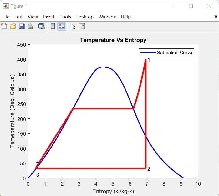
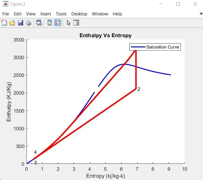
For Input given in the challenge:
- For Inlet pressure in Turbine as = 30 bar.
- Inlet temperature in Turbine = 400 deg.cel.
- Pressure in condenser = 0.05 bar.
Rankine Cycle:
1-2 is Isentropic Expansion in Turbine
2-3 is constant pressure heat removal
3-4 is Isentropic Compression in Pump
4-1 Constant pressure Heat addition in Boiler
Results of Rankine Cycle
At state point 1
P1 = 30.000000 in Bar
T1 = 400.000000 in Deg.Celcius
H1 = 3231.571027 in KJ/Kg
S1 = 6.923259 in KJ/Kg-k
At state Point 2
P2 = 0.050000 in Bar
T2 = 32.875490 in Deg.Celcius
H2 = 2110.708212 in KJ/Kg
S2 = 6.923259 in KJ/Kg-k
At state point 3
P3 = 0.050000 in Bar
T3 = 32.875490 in Deg.Celcius
H3 = 137.765119 in KJ/Kg
S3 = 0.476254 in KJ/Kg-k
At state Point 4
P4 = 30.000000 in Bar
T4= 36.935287 in Deg.Celcius
H4 = 134.754182 in KJ/Kg
S4 = 0.476254 in KJ/Kg-k
Turbine Work Done = 1120.862815 in KJ/Kg
Pump Work Done = 3.010937 in KJ/Kg
Net Work Done = 1117.851878 in KJ/Kg
Thermal Efficiency = 36.096803 in percent
Sp. Steam Consumption = 3.220462 in KJ/Kw
From the two different input values, it is seen that increasing the pressure and temperature in the turbine results in lowering the efficiency of the Rankine cycle.
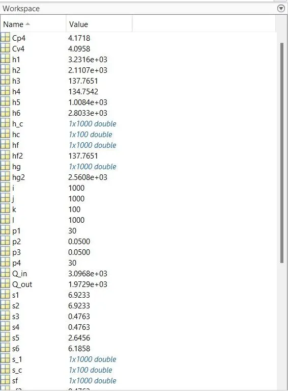
WORKSPACE:
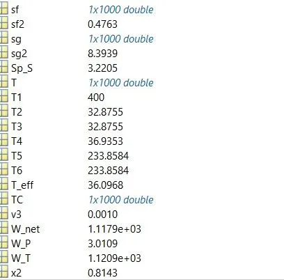
Errors & Command window Execution:
- I have found a few errors and solutions were found during execution.
- Use of the semi-colon(;) in coding results in no output in the command window.

Conclusion:
So, we have created the Rankine cycle simulator for the given input, in which we have taken the data from the XStream function file.
References: