Project - A project on design of road from a given topographic data
1.Point creation and grouping them with the help of description.
1 As data is provided in word ,copy that survey data in word to text format file
2.The open the new civil 3D file and set the corrdinates
3.The go the prospector tab and click on create surface and name the file name and go the defination and click on point file and select the text file and select the file format PNEZD then click ok
4.Then the surface is created.
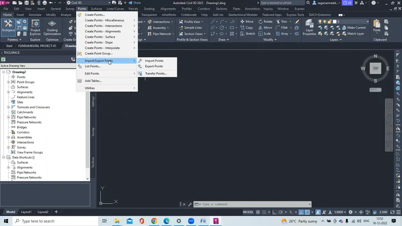
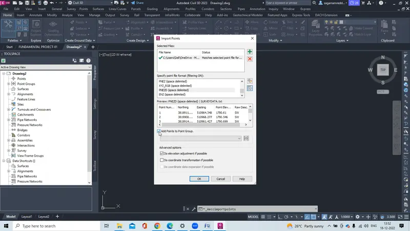
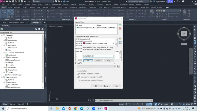
5.Click on Points in menu bar then click on import /export points and select the point file and click on point group and name the point group file in survey tab and save it the point group is created.
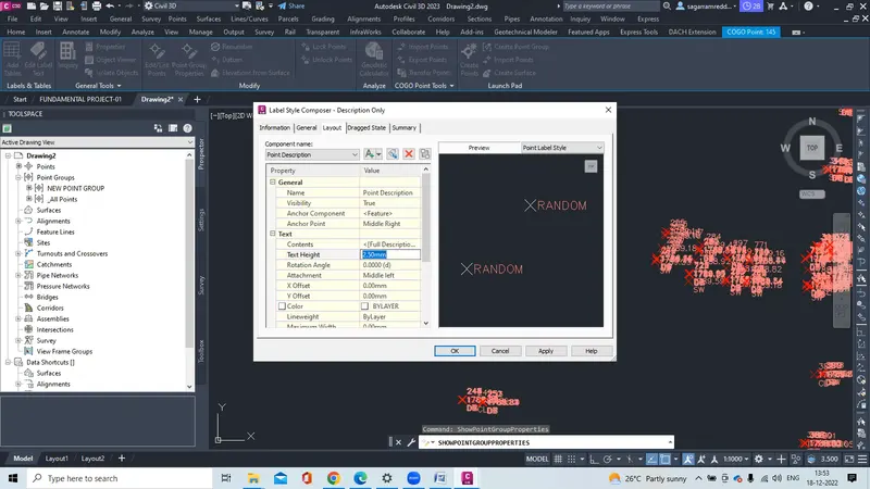
6.click on point group and click on point group properties and edit the point style and lables

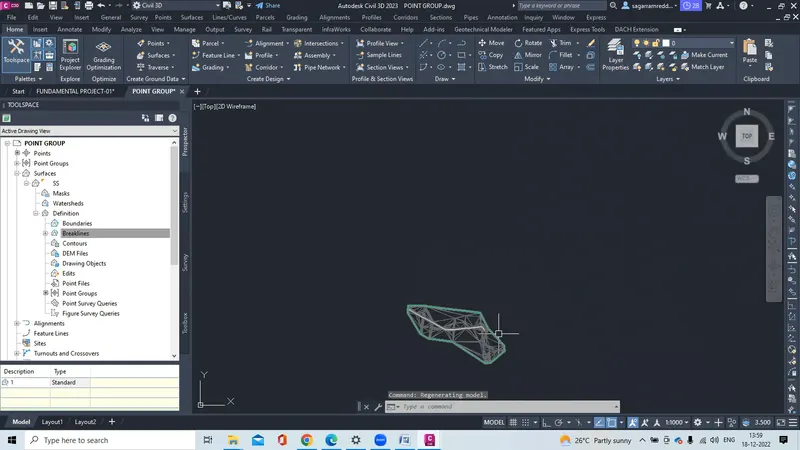
2.Preparation of surface and importance of breaklines.
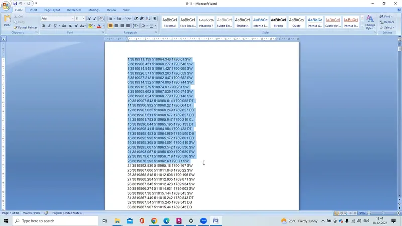
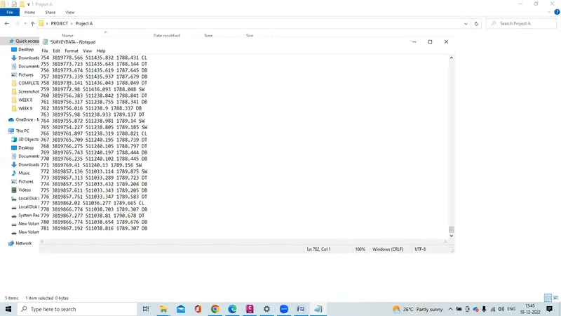
1 As data is provided in word ,copy that survey data in word to text format file
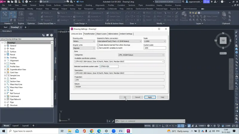
2.The open the new civil 3D file and set the corrdinates
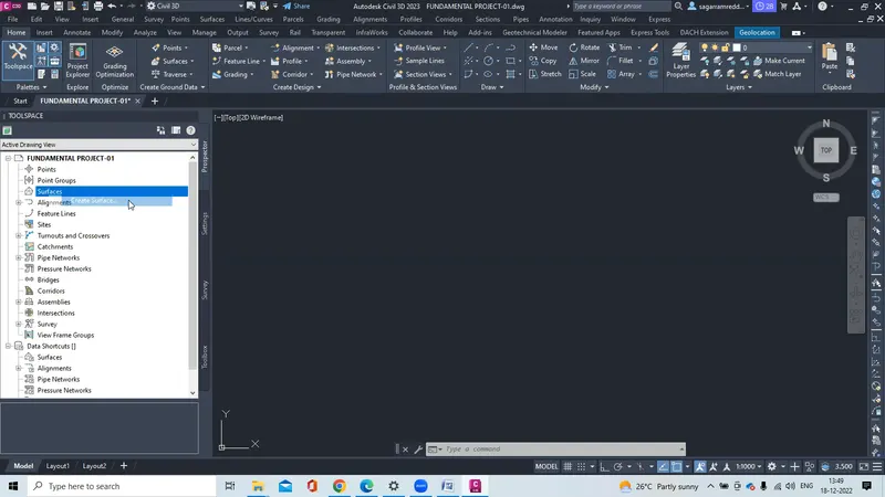
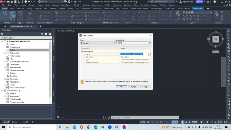
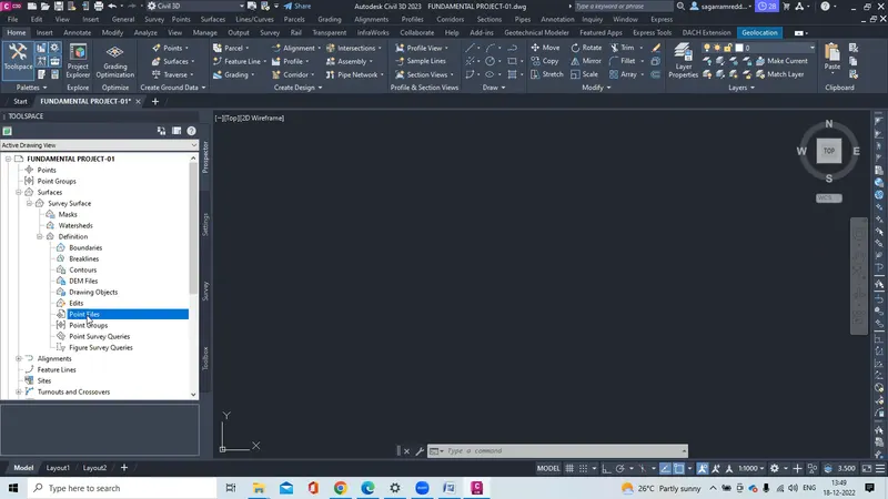
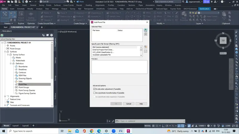
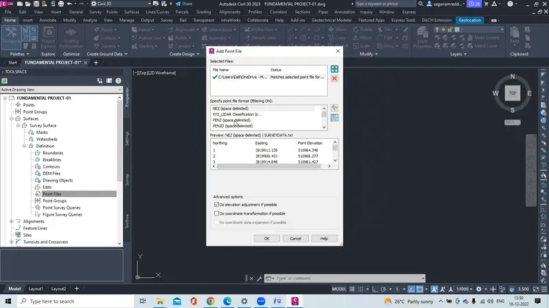
3.The go the prospector tab and click on create surface and name the file name and go the defination and click on point file and select the text file and select the file format PNEZD then click ok
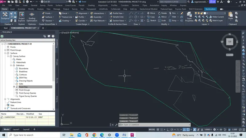
4.Then the surface is created.
 3.Horizontal alignment design and adding super elevation.
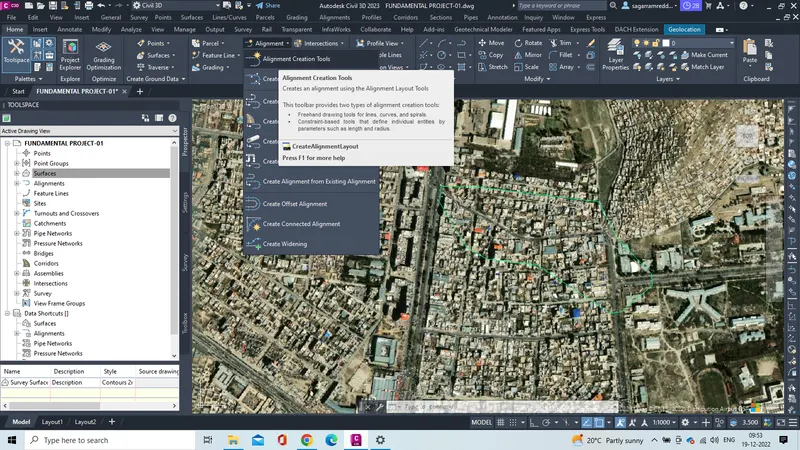
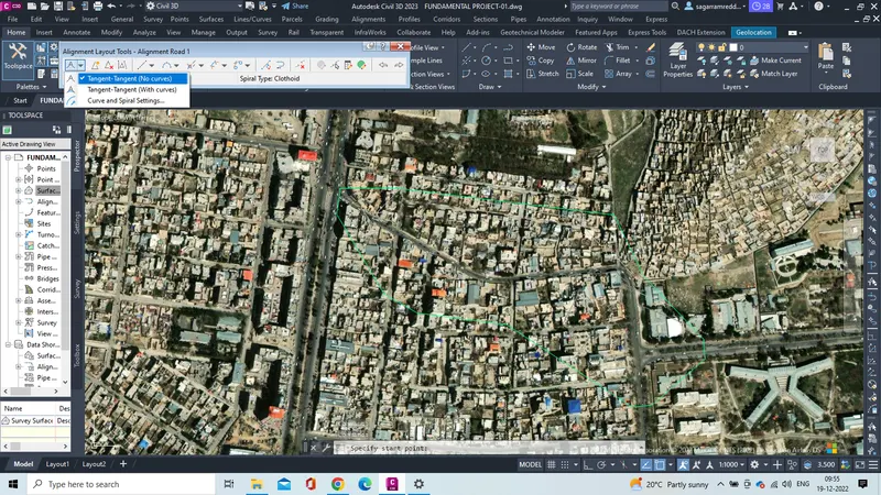
1.Go to alignment option in menubar and click on create alignment by layout.
2.Then create alignment tab opens and name the alignment as NH-o4
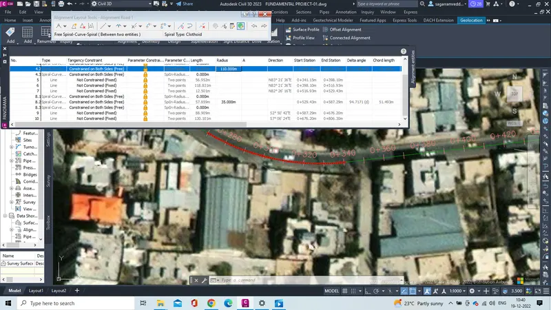
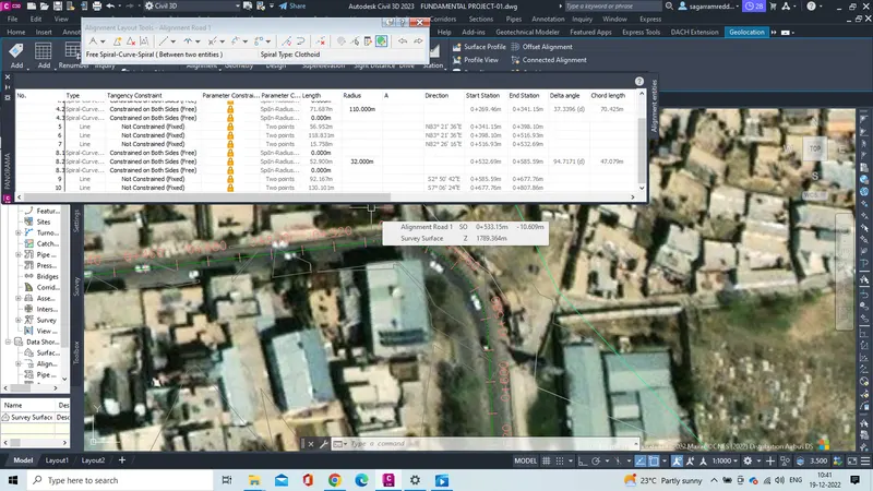
3.Then a panrama window open which has alignment creation tools
4.Then click on the line command and select the fixed line (two point) option and draw the lines .
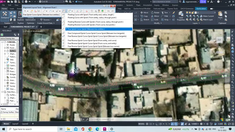
5.Then add the curve to it so click on free spiral-curve-spiral ( between to entities ) based on the curve radius select the lenght from the table 9
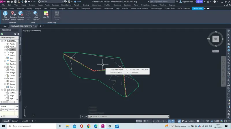
6.Now to the changes in curve radius and adjust if required then the alignment is ready
7.Select the alignment and go to alignment properties and assign design speed to the curves
8.Then again select the alignment and click on superelevation and tab opens set the standards of IRC and check the other standards also then click assign superelevation
9.Then the assigned superelevation values tab opens , then copy the radius and superelevation values in the execel sheet provide.

4.Vertical profile design.
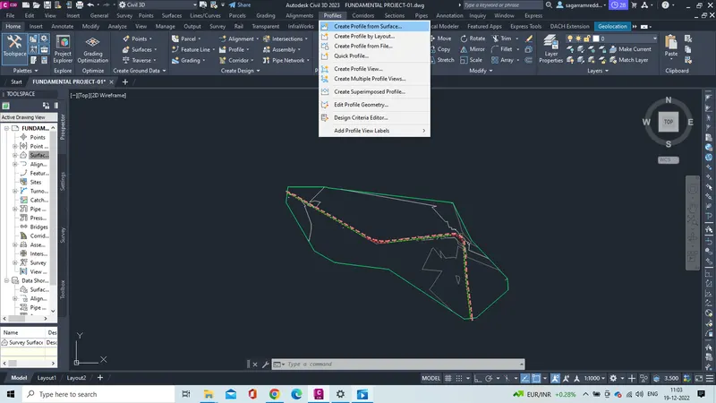
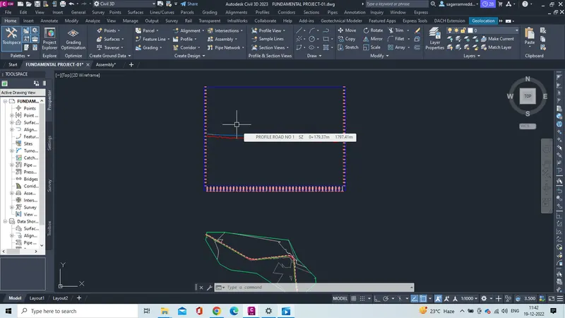
1.Now go to profiles and select create profile from surface option and a tab opens
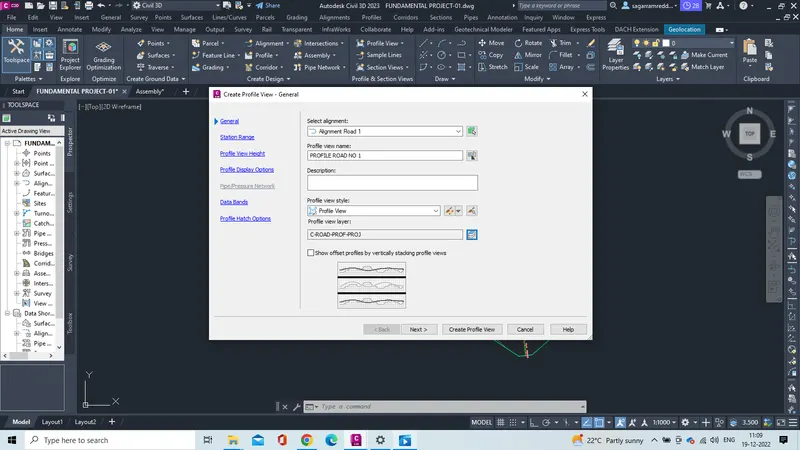
2.Name the profile and select the alignment and set the alignment offset to -15,+15 and click ok
3.Then select the profile style
4.Then click on draw profile.
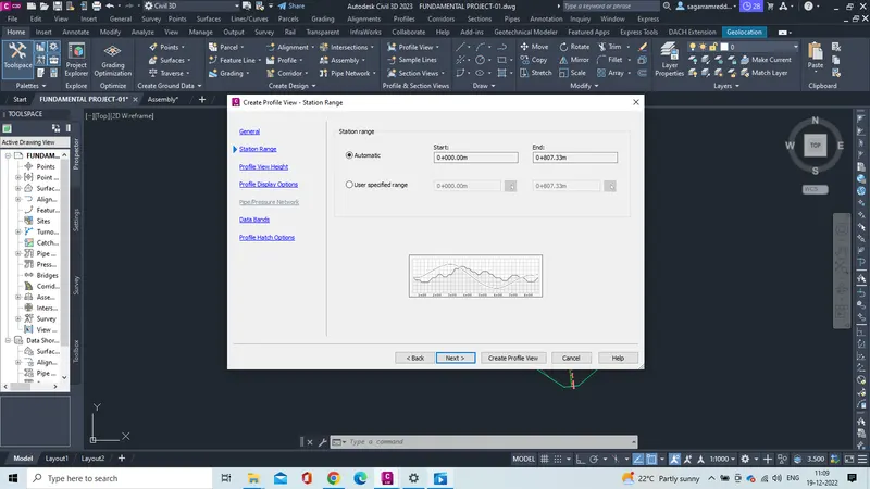
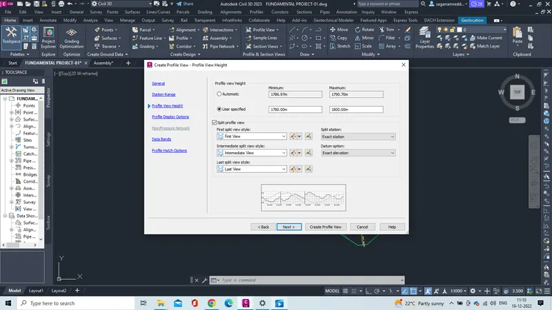
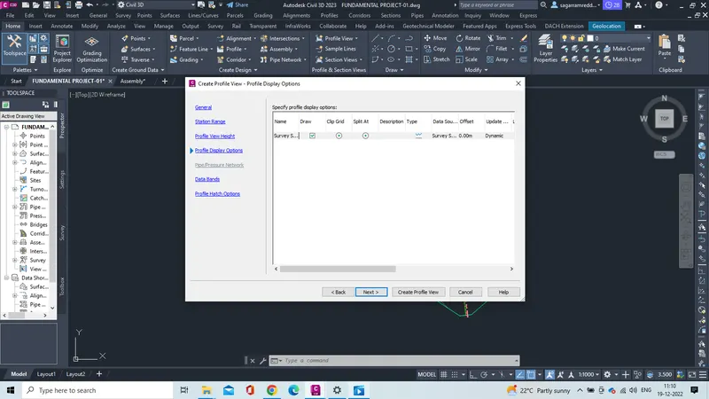
5.Then create profile general tab opens and do all the settings , set profile view height to user specified
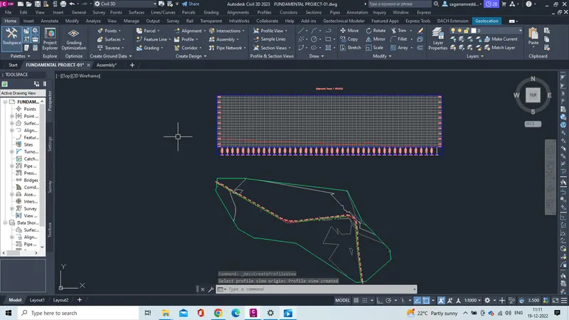
6.Then click on create profile view and the profile is created
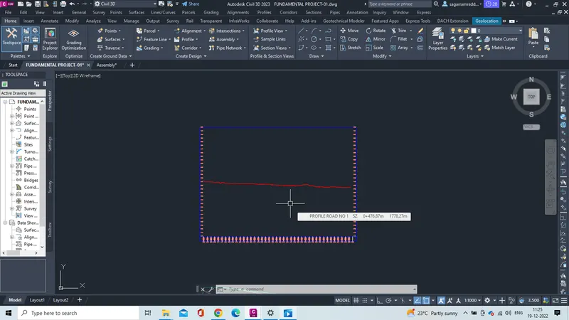
7.Now profile design is done.
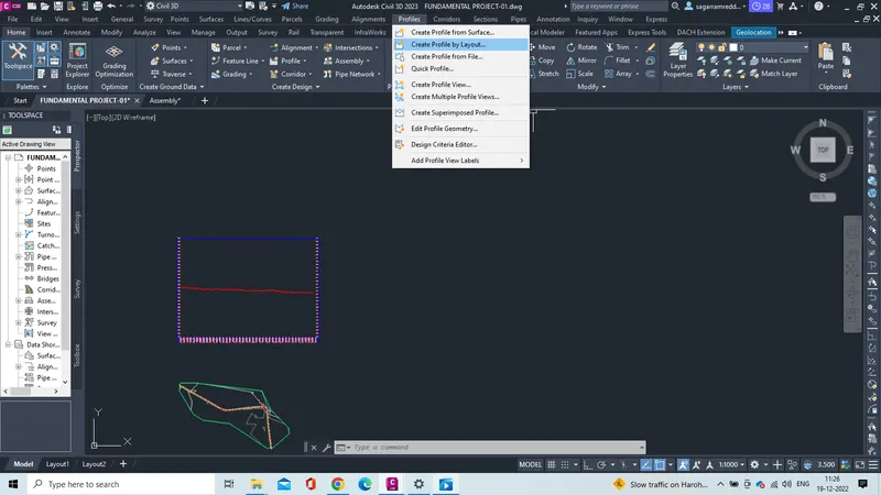
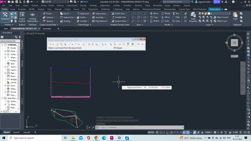
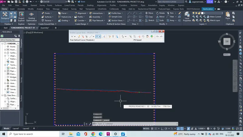
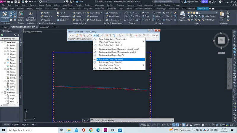
8.click on create profile by layout, a profile creation tool opens
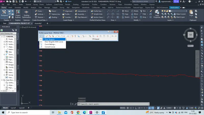
9. Now select the tanagent line open in profile creation tool and draw the tangent at first and last point.
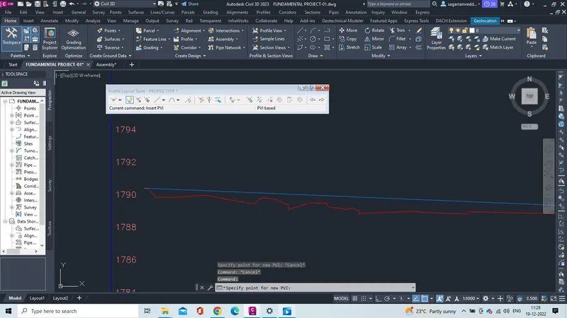
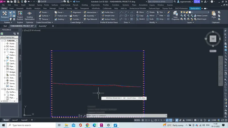
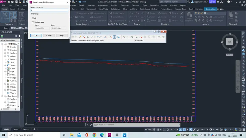
10. Now add the PVI along the tangent and create the profile.
11.Then add the curve radius of vertical curves then the profile is ready.
6.Corridor modelling and extraction of finished surfaces.
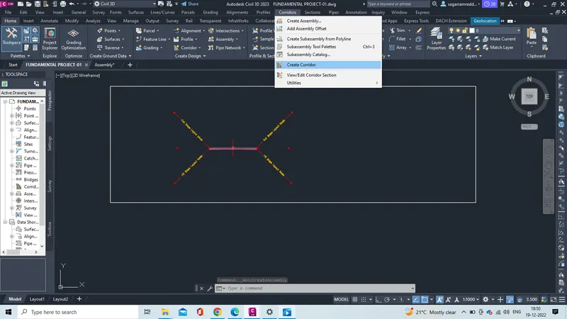
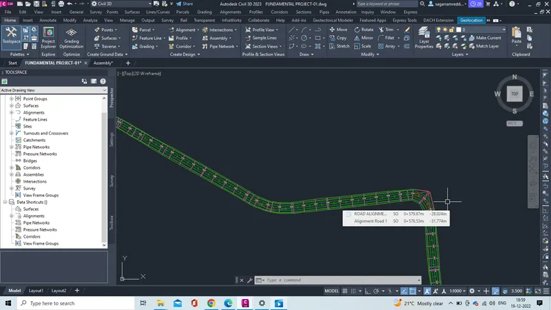
1.click on corrioder in menu option and select create corrioder
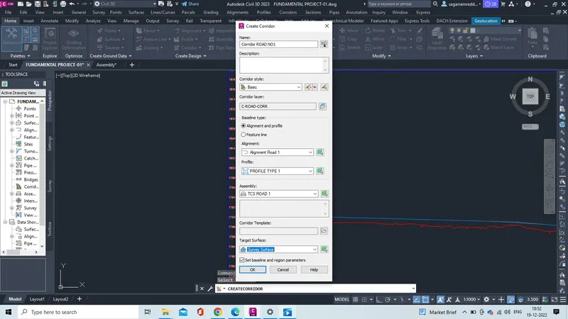
2.Then new tab opens create corridor then name the corridor,then select the alignment ,assembly and profile and target surface then click ok
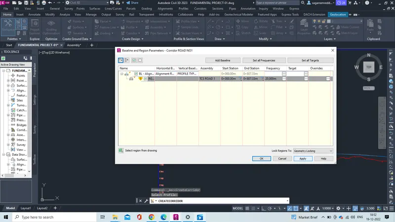
3.Then baseline and region parameter tab opens and check the alignment and click on apply and click ok
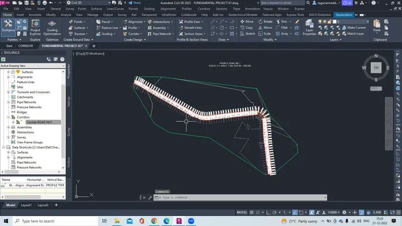
4.Then click on rebuild corridor then the corridor is created and go to corridor properties and change the station length upto which the corridor has to build.
5.Then the corridor is created.
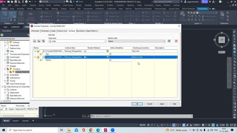
6.Then go to corridor properties and create the surfaces for top and bottom surfaces
7 Cross sections production based on corridor modeling.
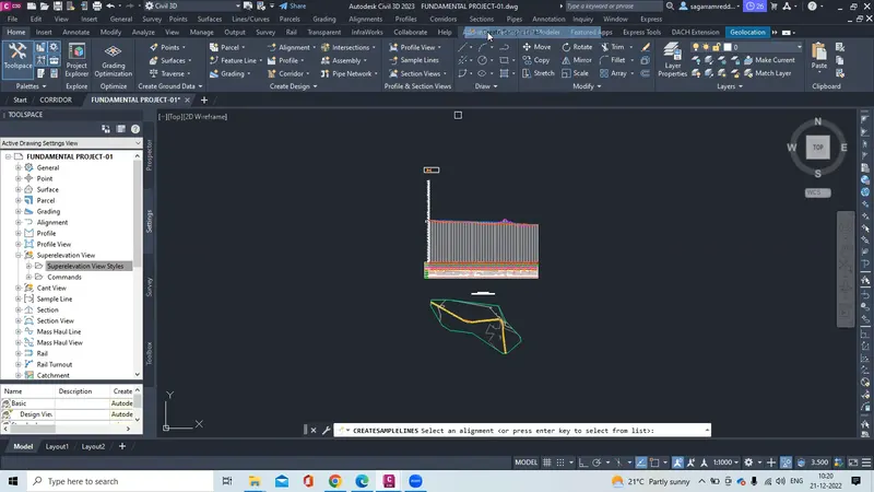
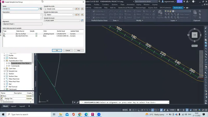
1.In menu bar click on section and select the create sample lines
2.Then select the alignment where u want to create sample lines
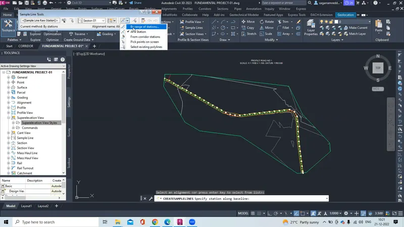
3.Then a panarama window open in that select the sample lines by range of stations
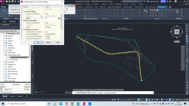
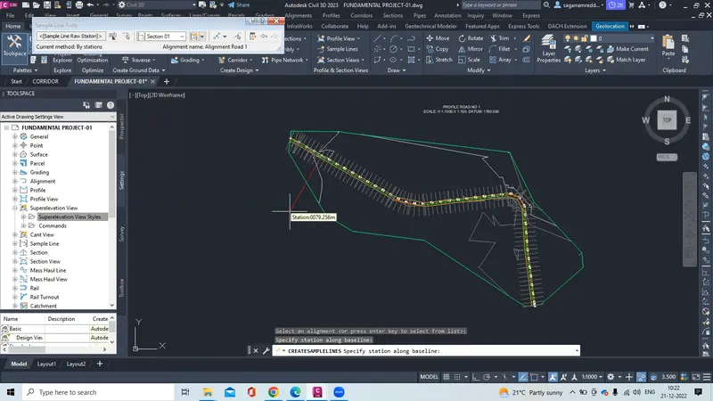
4.Then new tab open set the intervel upto what lengh sample lines to be created then set the range and do necesssary setting and click ok to create the sample lines
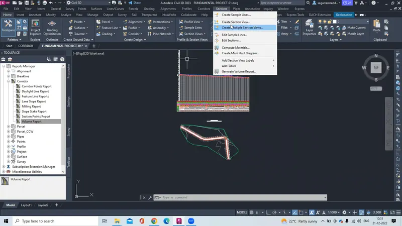
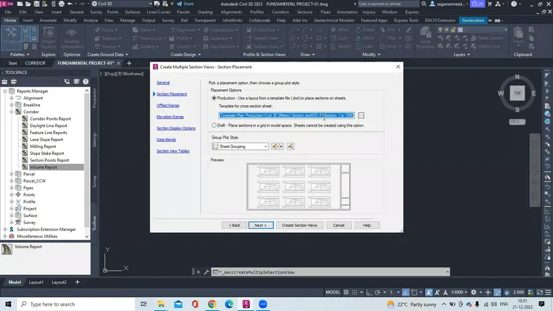
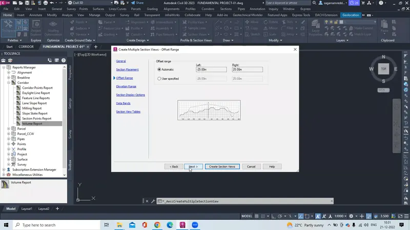
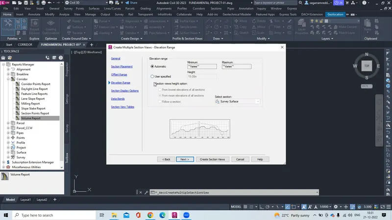
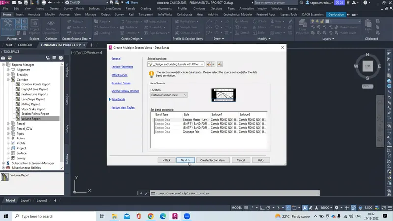
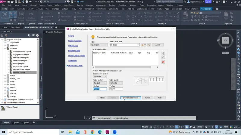
5. Click on section and click on create multiple section views and select the alignment ,profile and do the necessary setting and click on create section views.
8.Earthwork quantities and material quantities takeoff.
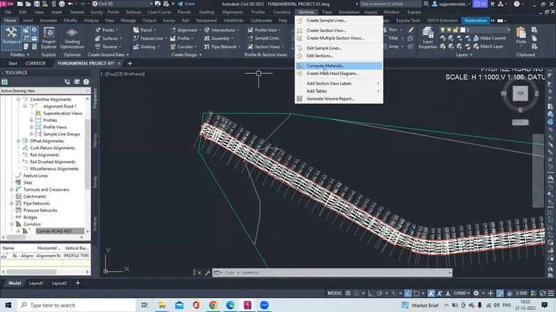
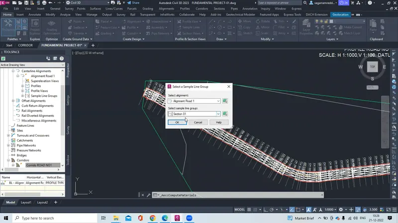
1.Now go to section and select the compute material , then select the alignment and sample lines and click ok
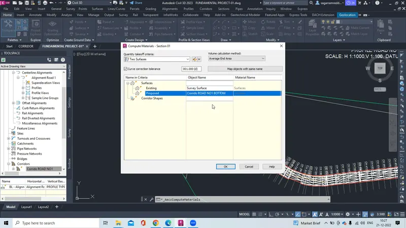
2.Then the surafce data and datum files are selected and click ok
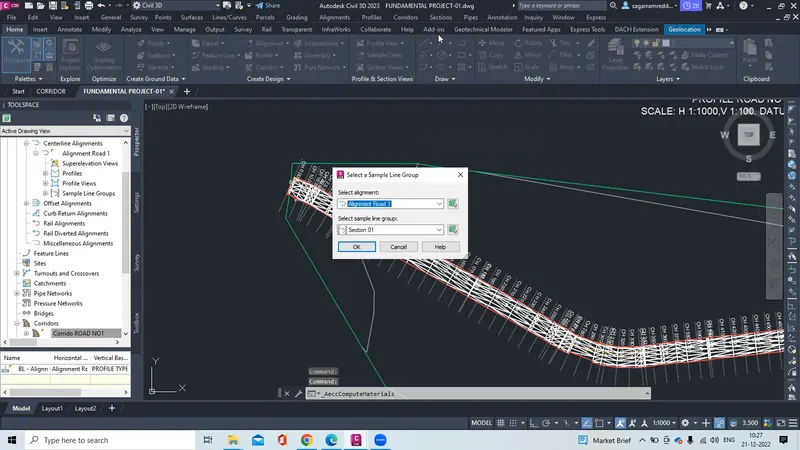
3.Then again go to section and again select compute materials, then aagain select the alignment and sample lines click ok
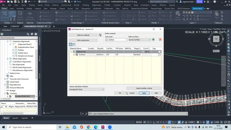
4.Then the material list is available, then click apply and click ok
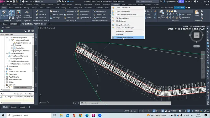
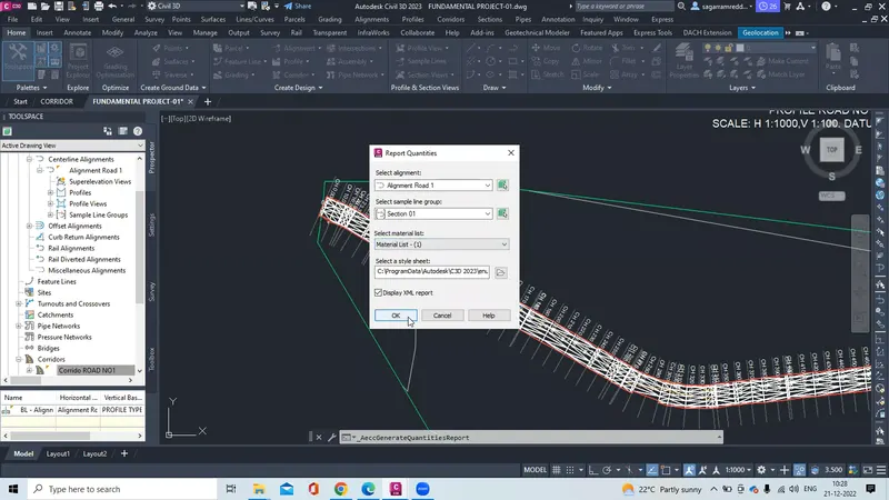
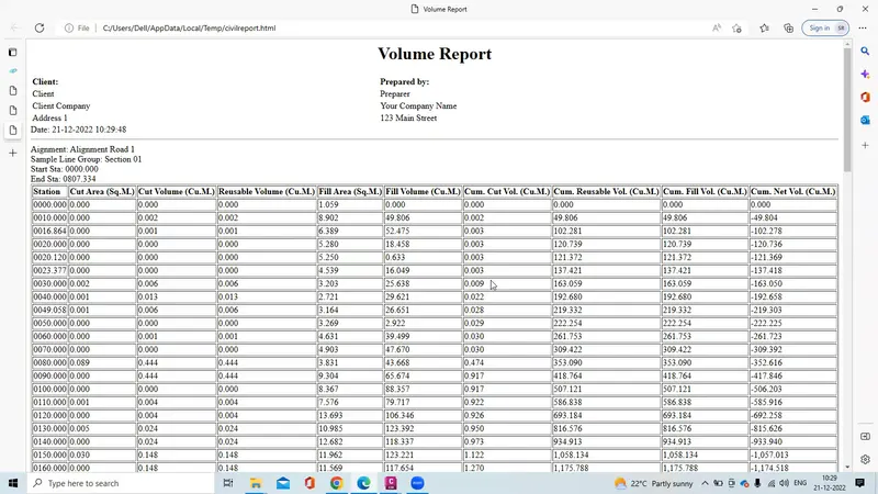
5.Then in section click on generate volume report then file opens and copy the quantity and paste it in the execel sheet
6. Now in sections click on create multiplte section view and set the raange,select alignment and sample group and set the intervel and range of sections then click create section view
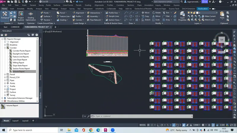
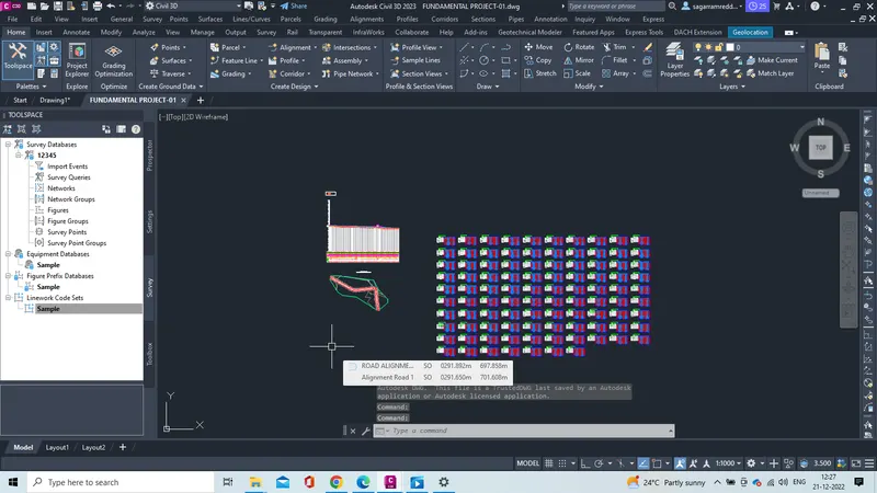
7.Now the sections views are created detailed section views