Project 2 - Lane National Highway Roadway Design in Civil 3D
1.Creation of surface
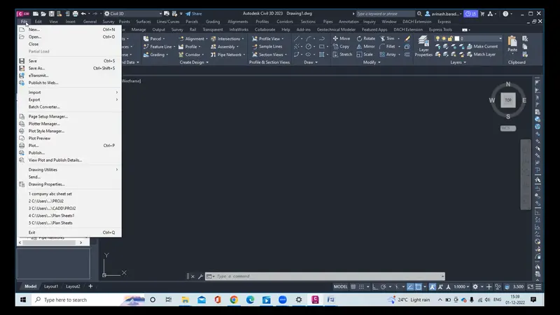
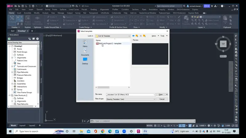
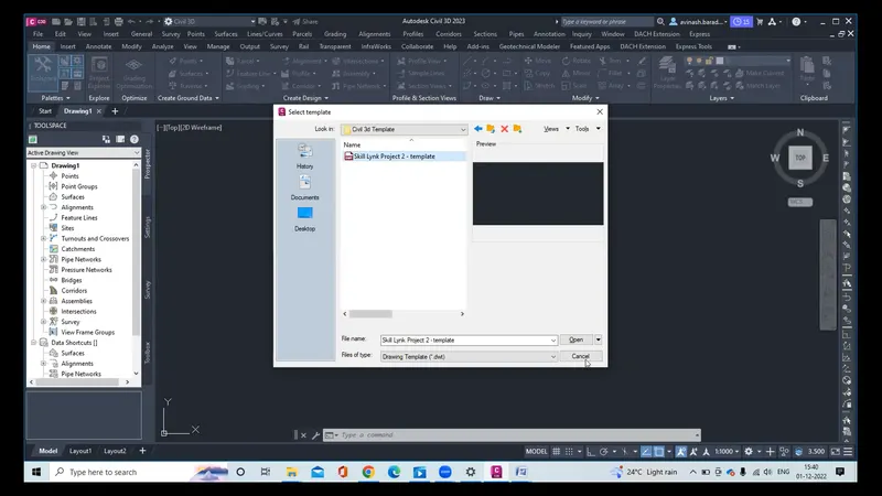
1.open new file go to templete provided from the dashboard and open it.
2.when the templete is open two viewports are avilable
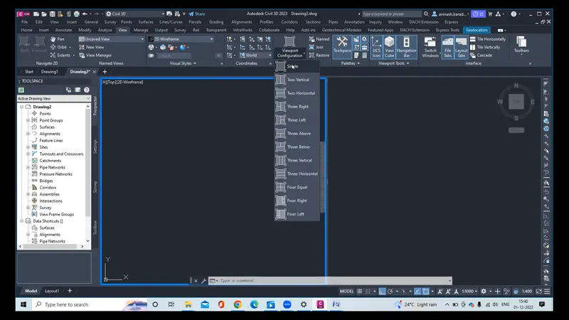
3.Go to view and click on single view then only one viewport is set
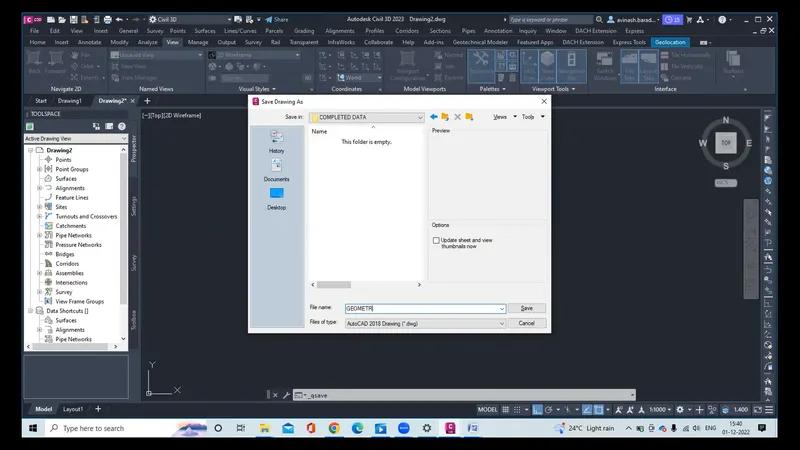
4.Then click on save as and save this file in completed assignment file and name as project file 2
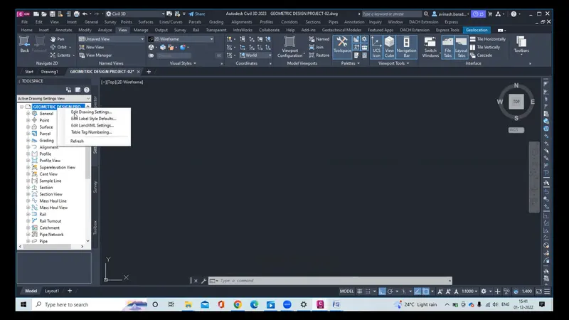
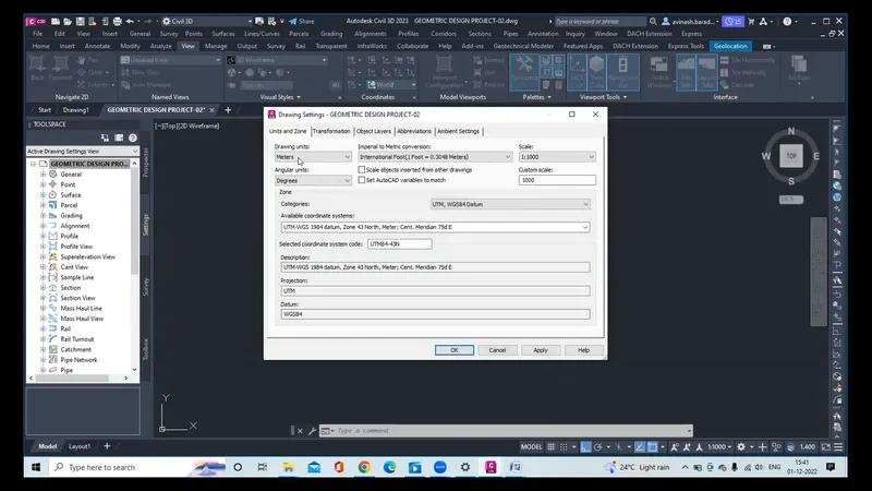
5.Now check the corridinates and save them
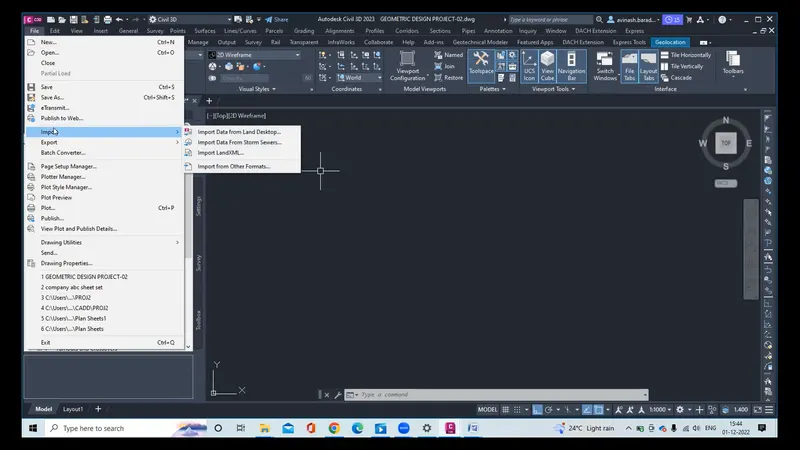
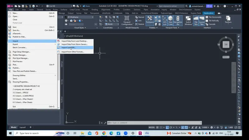
6.Now go file and click on import and click on import landXML
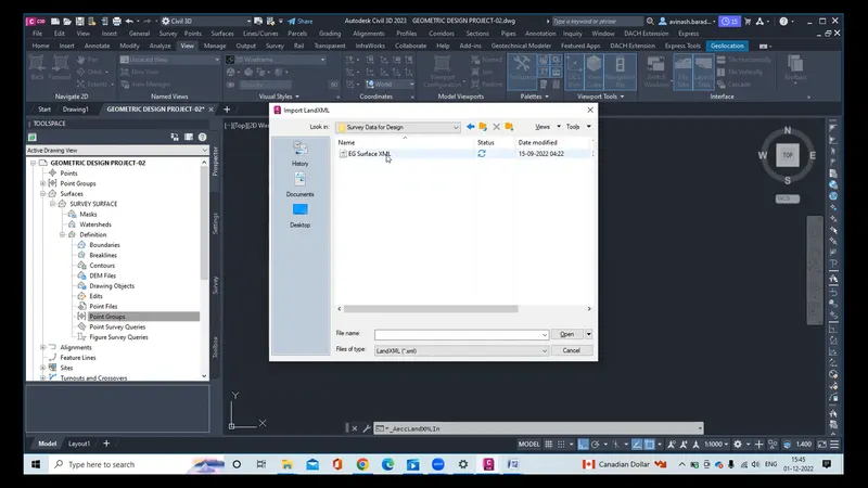
7.Then import landXML tab open select the loaction of file where u want XML document to import from
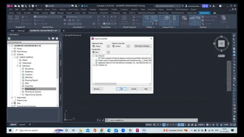
8.Then select and click open then the Survey data XML file opens.
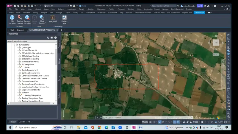
9.Now on the arial view check the loaction ,then select the survey data and click on properties and change the style.
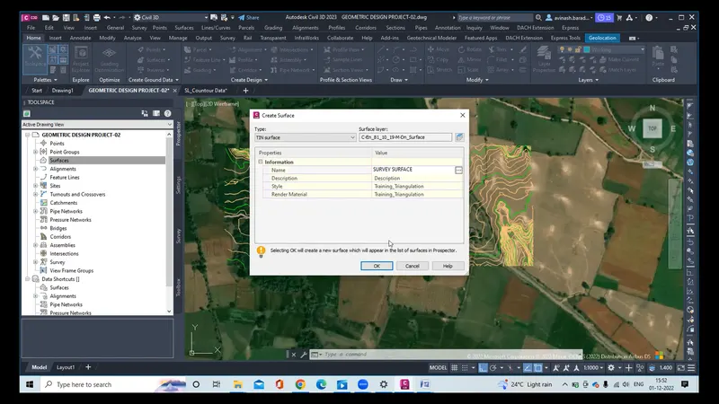
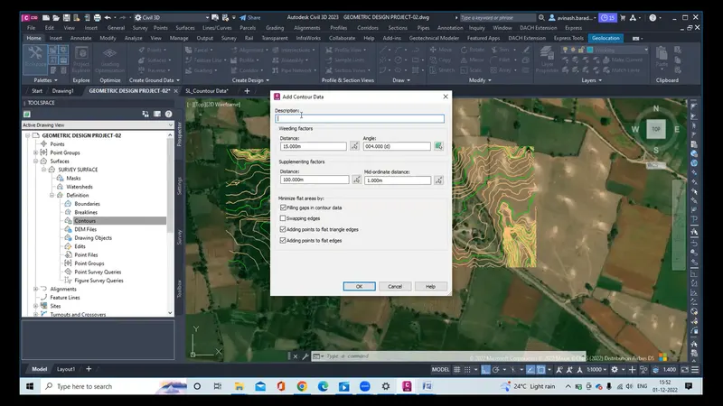
10.Now go survey in prospector tab click on crete surface and name it as survey surface
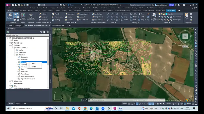
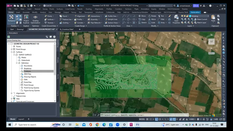
11.Now right click and add the surface data type its countors and name it and select the countours and surface file is created
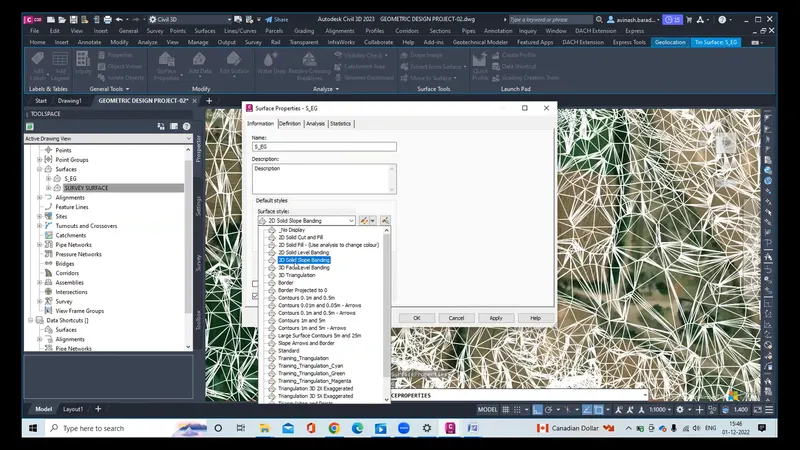
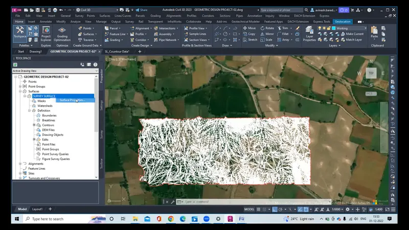
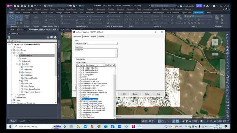
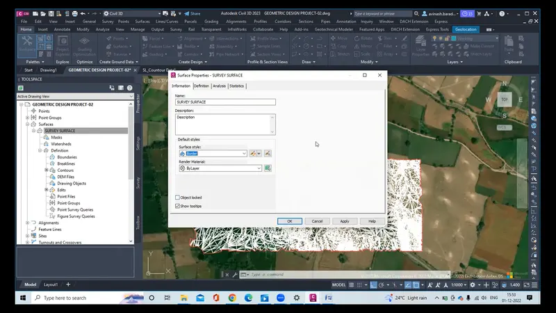
12.Now go to survey right click and select the surface properties and select to border style click ok
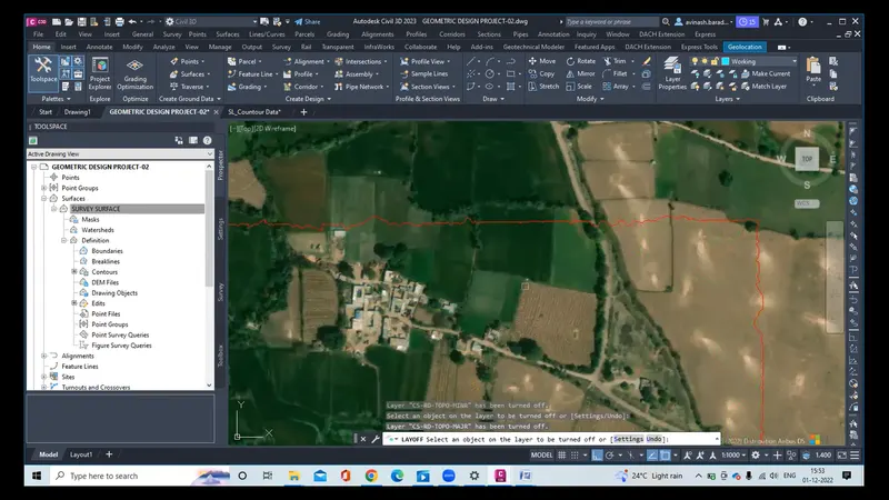
13.Then type layeroff and off the countour laayers.
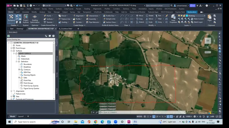
14.Now the surafce is created.
2.Alignment & profile design.
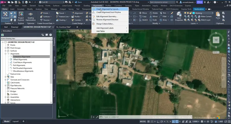
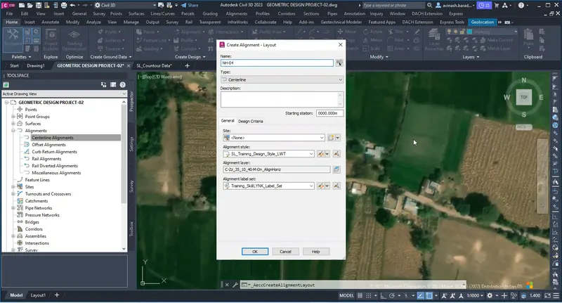
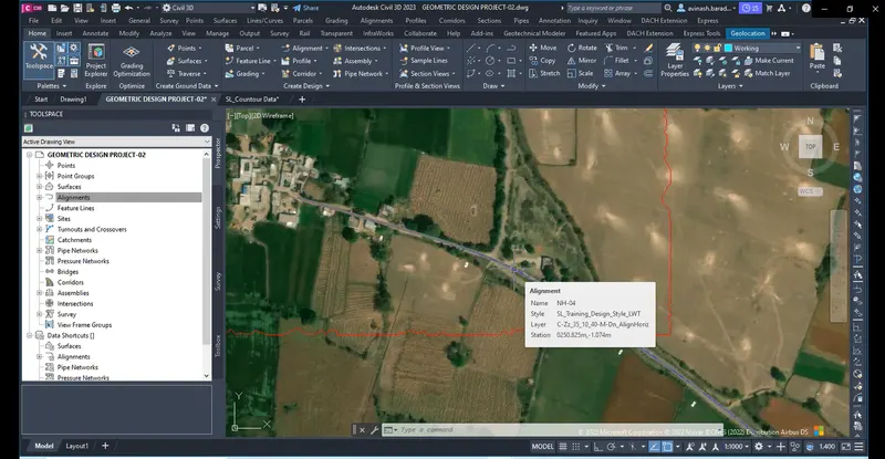
1.Go to alignment option in menubar and click on create alignment by layout.
2.Then create alignment tab opens and name the alignment as NH-o4
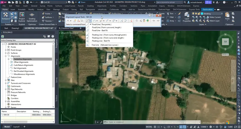
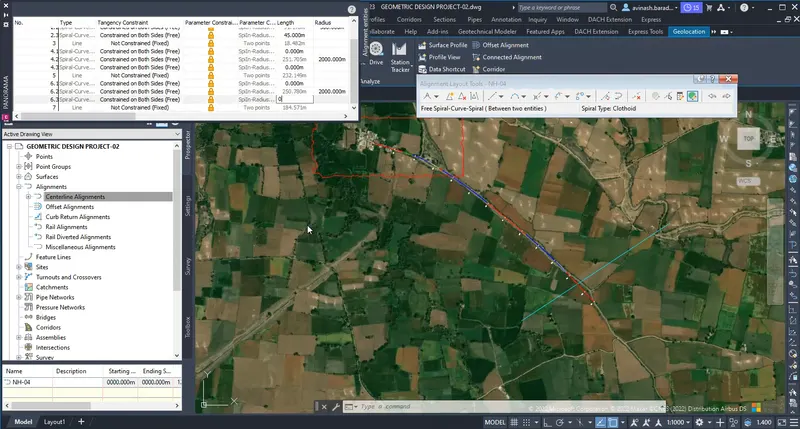
3.Then a panrama window open which has alignment creation tools
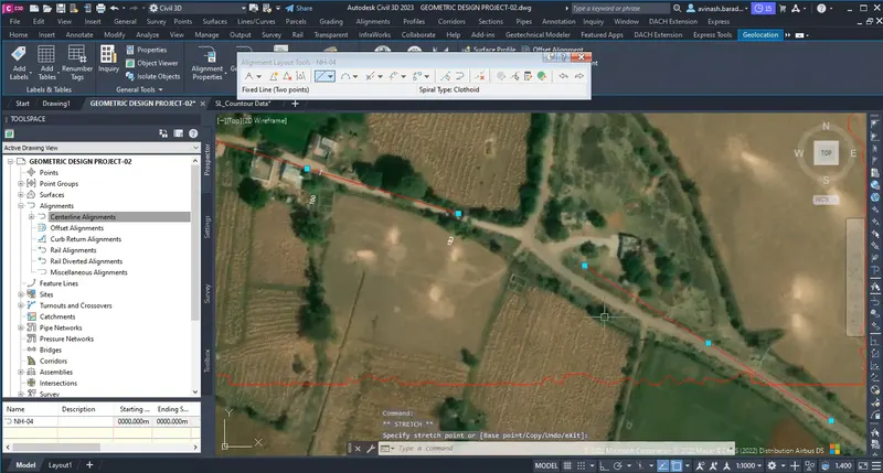
4.Then click on the line command and select the fixed line (two point) option and draw the lines .
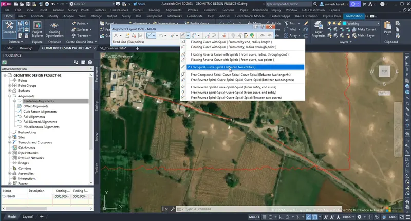
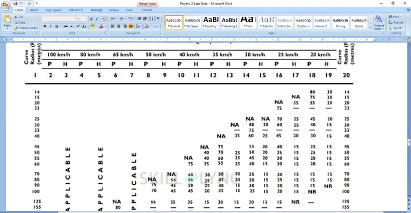
5.Then add the curve to it so click on free spiral-curve-spiral ( between to entities ) based on the curve radius select the lenght from the table 9
6.Now to the changes in curve radius and adjust if required then the alignment is ready
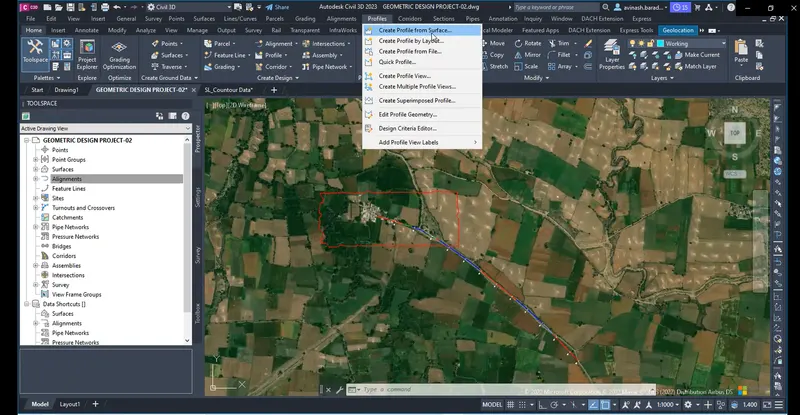
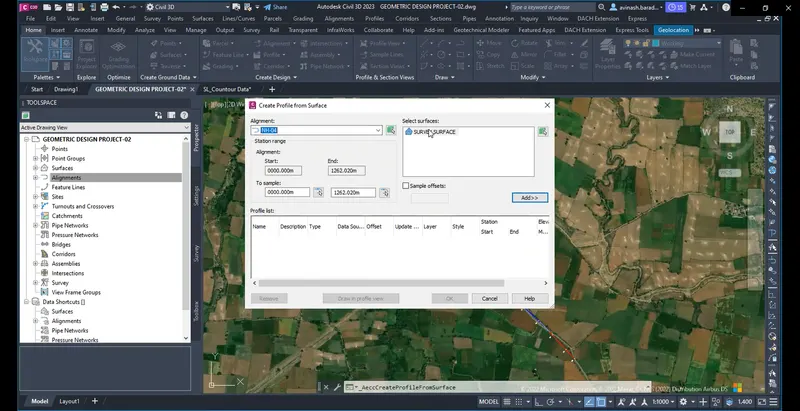
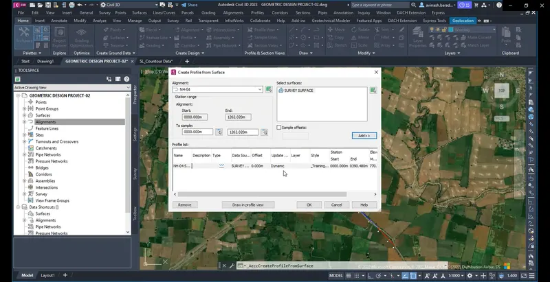
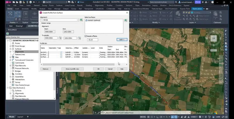
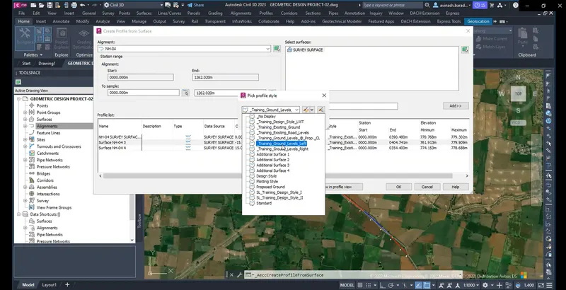
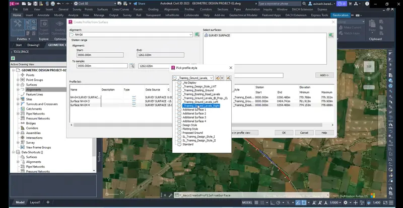
7.Now go to profiles and select create profile from surface option and a tab opens
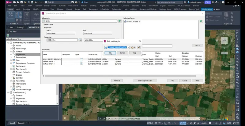
8.Name the profile and select the alignment and set the alignment offset to -15,+15 and click ok
9.Then select the profile style
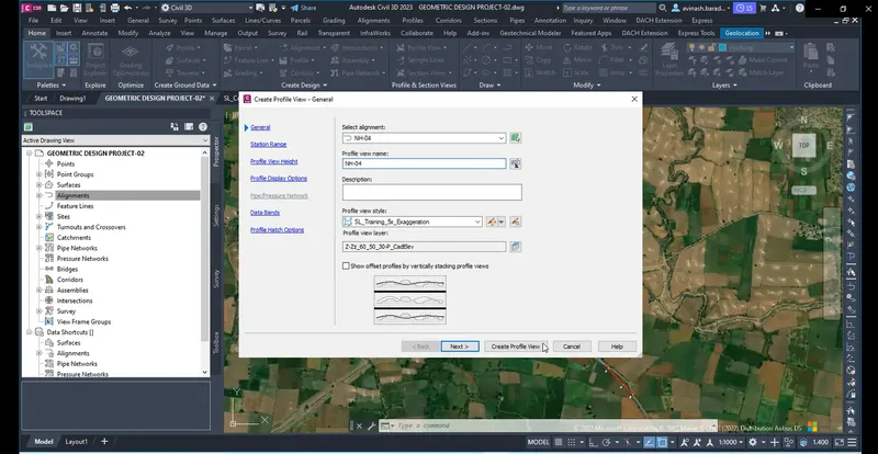
10Then click on draw profile.
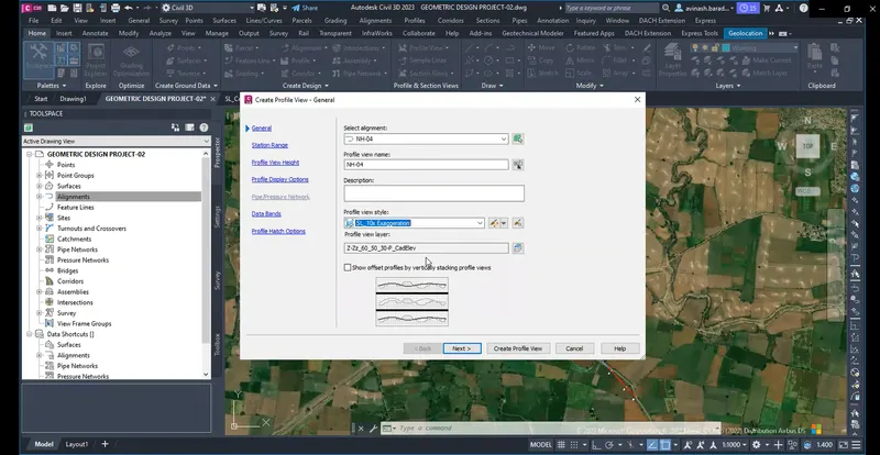
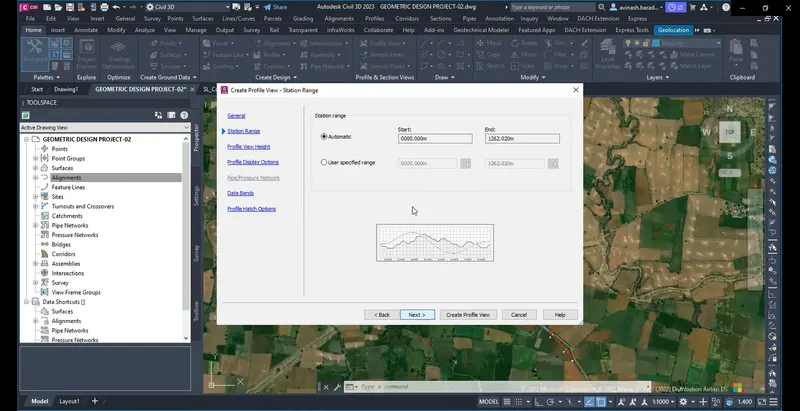
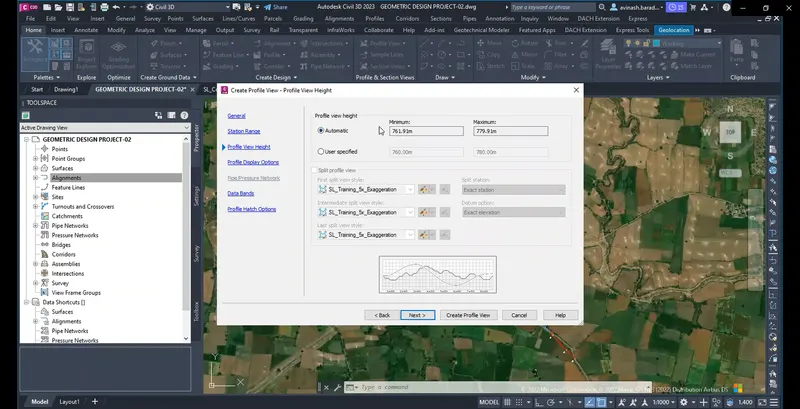
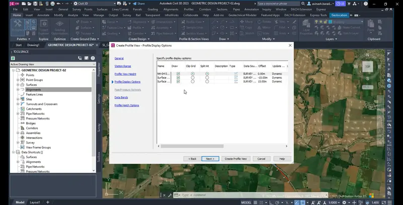
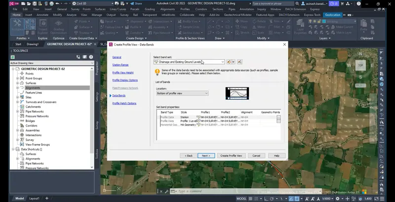
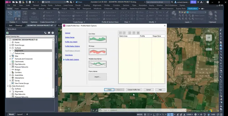
11.Then create profile general tab opens and do all the settings , set profile view height to user specified
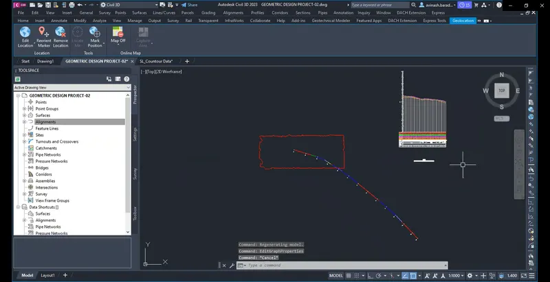
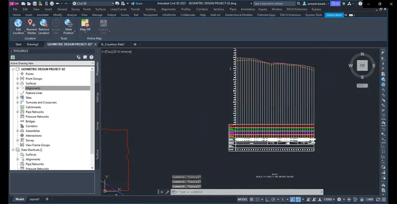
12.Then click on create profile view and the profile is created
13.Now profile design is done.
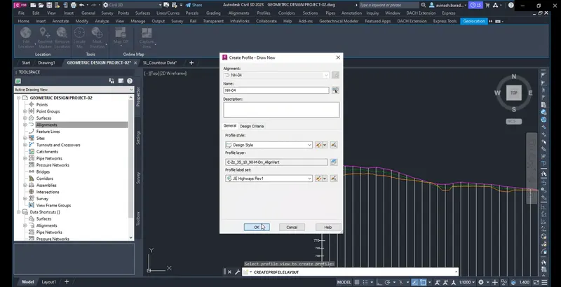
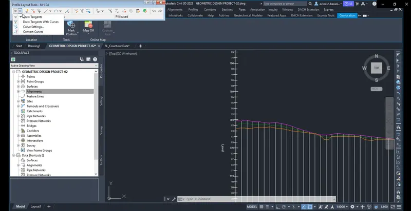
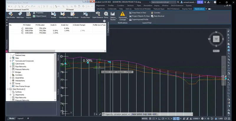
14.click on create profile by layout, a profile creation tool opens
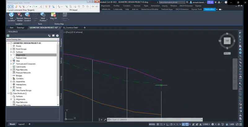
15. Now select the tanagent line open in profile creation tool and draw the tangent at first and last point.
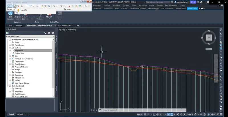
16. Now add the PVI along the tangent and create the profile
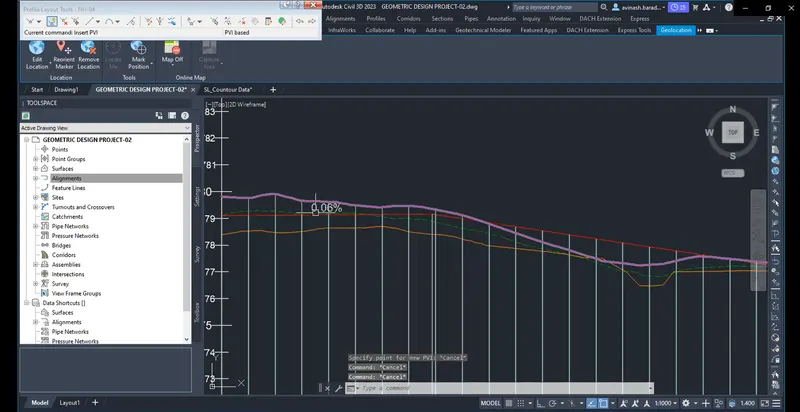
17.Then add the curve radius of vertical curves then the profile is ready
3.Creation of assembly & subassembly.
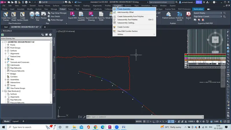
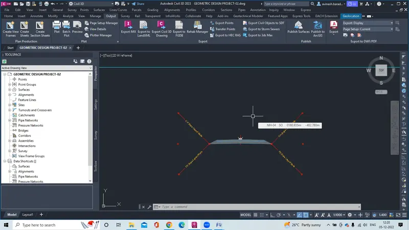
1.In menu bar click on corridor option and click on create assembly
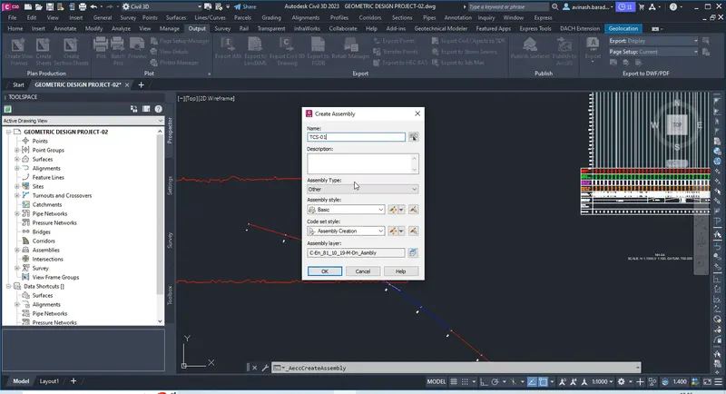
2.Then new tab opens create assembly and name it as TCS 1
3.Then select the location where u want to draw the assembly and draw the rectangle around it to esaily asses.
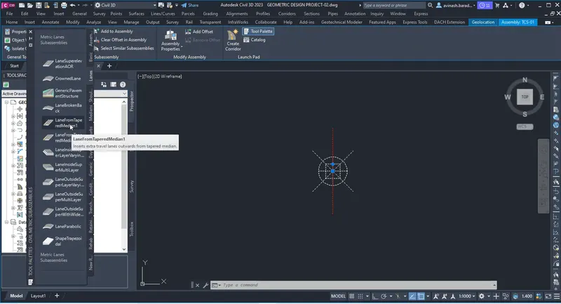
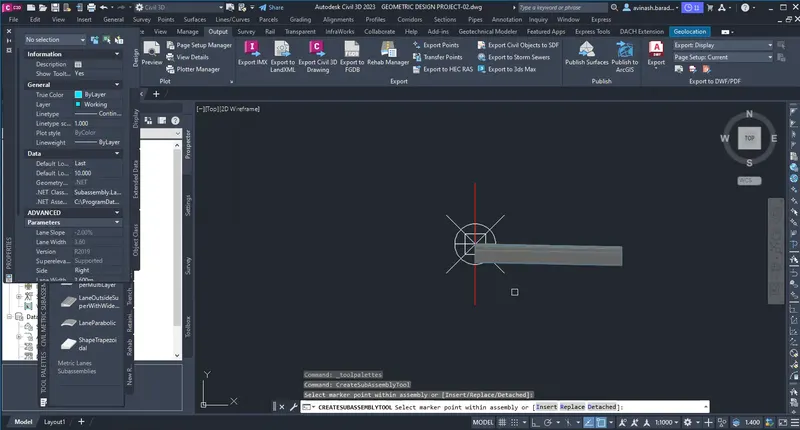
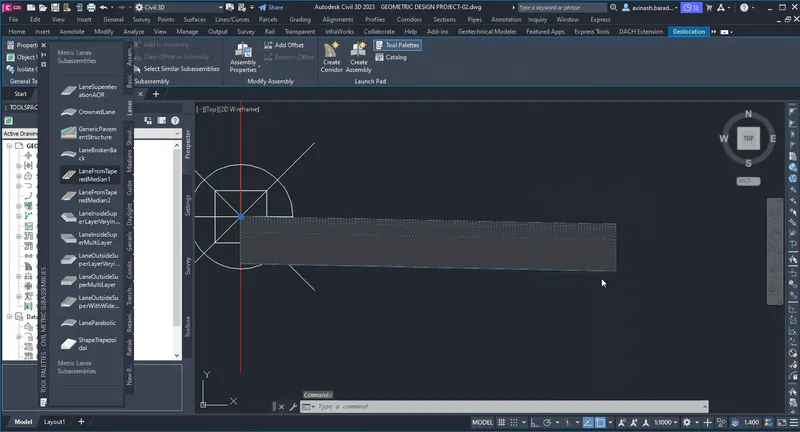
4.Select the assembly and click on tool plalet then the assemblies open then click on lane and select the lanefromtapred median 1
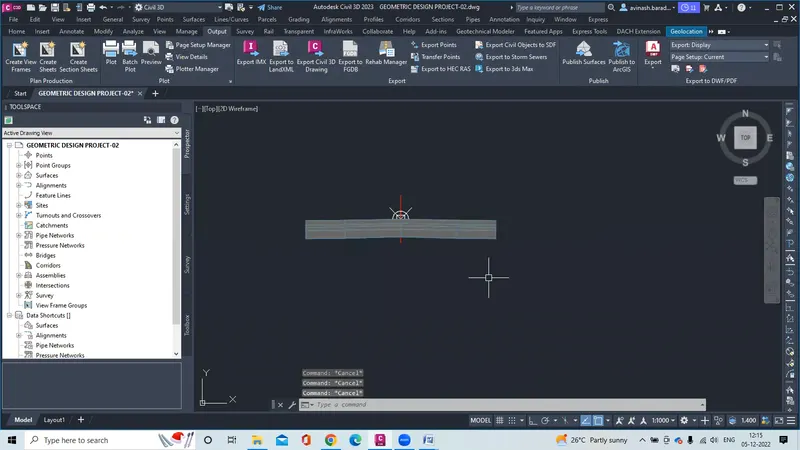
5.click on right side of TCS and the subassembly is created
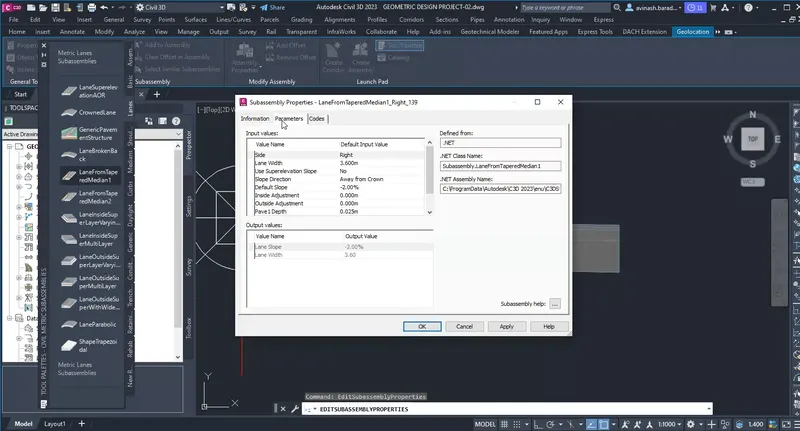
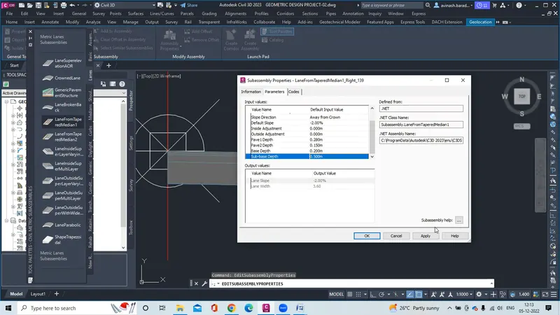
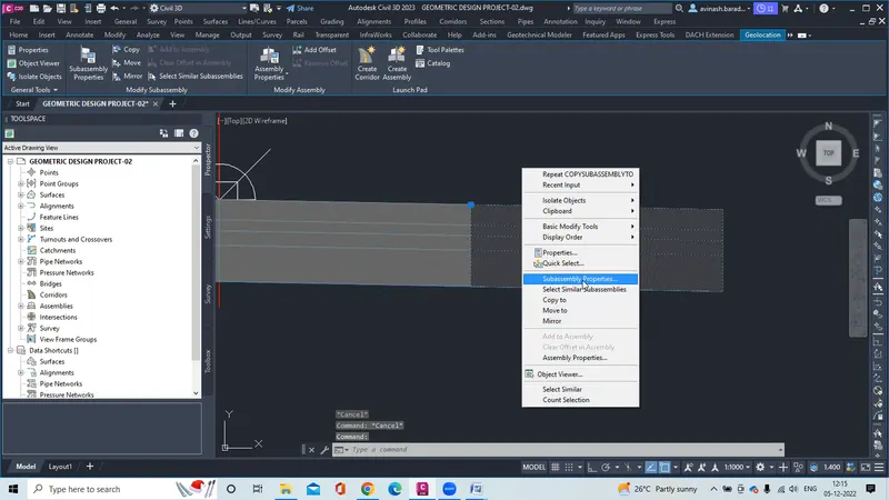
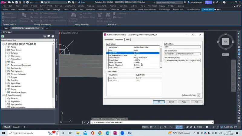
6.Then select the lane and click on the subassembly properties and set the lane width and layer thickness and slope
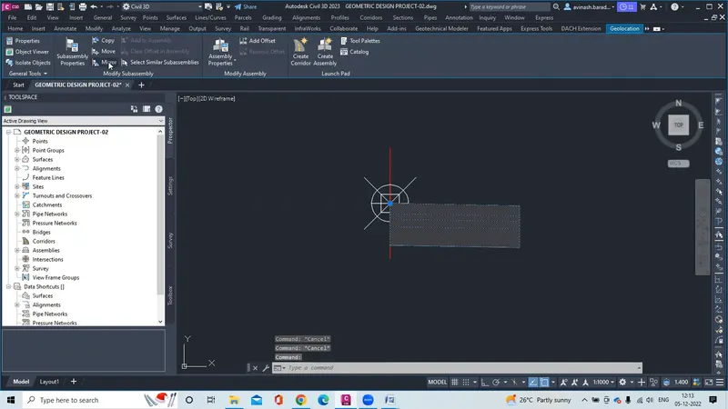
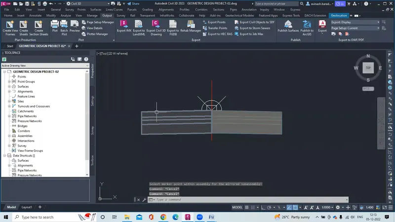
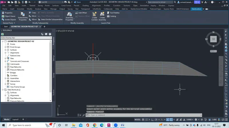
7.Then create the mirror image on this side also by selecting the lane on right side
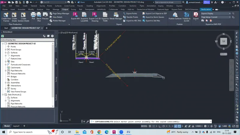
8.Now silimarly for paved shoulder the assembly is selected and copied and width and other properties are changed
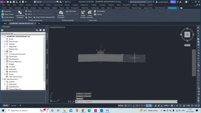
9.Then the mirror image is creadted .
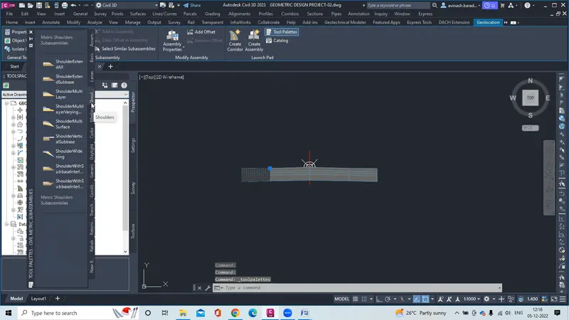
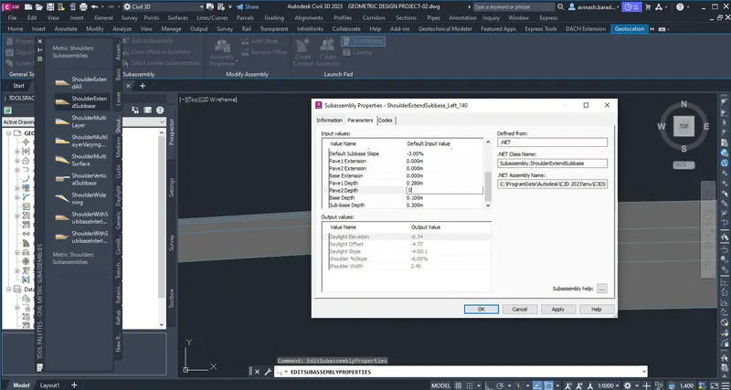
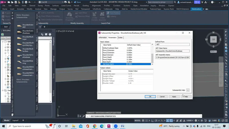
10 Then for unpaved shoulder then again go tool palet and select the unpaved shoulder extended assembly and again change the paramets and mirror on both sides and the carriage way is ready
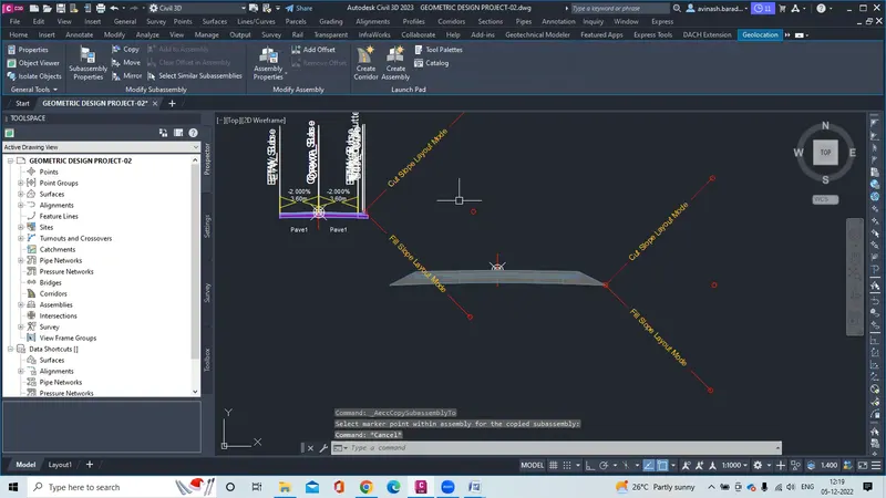
11. Then set the proper cut and fill conditions from copying it from the other assembly. Now select the cut and fill conditions and go to subassembly parameters and change the conditions of cut and fill
4.corridor development.
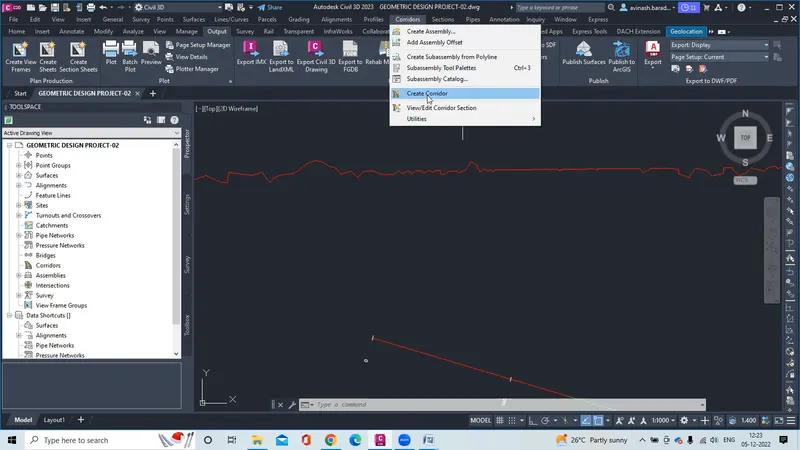
1.click on corrioder in menu option and select create corrioder
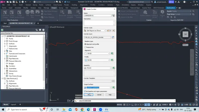
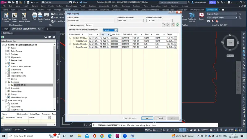
2.Then new tab opens create corridor then name the corridor,then select the alignment ,assembly and profile and target surface then click ok
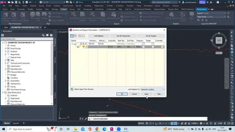
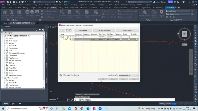
3.Then baseline and region parameter tab opens and check the alignment and click on apply and click ok
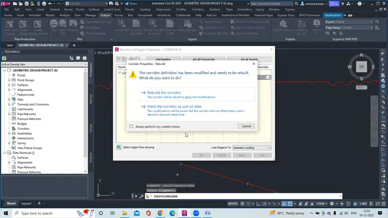
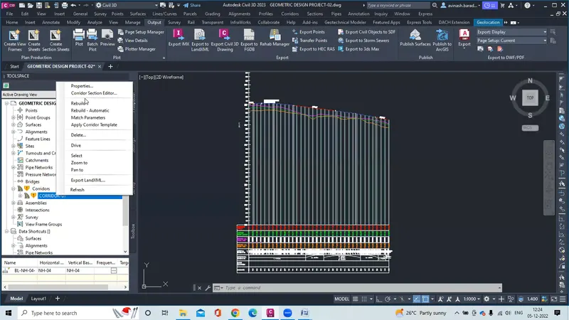
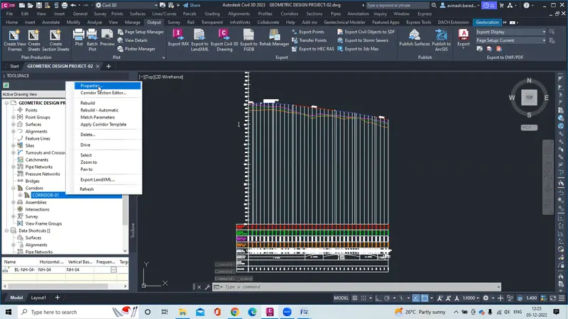
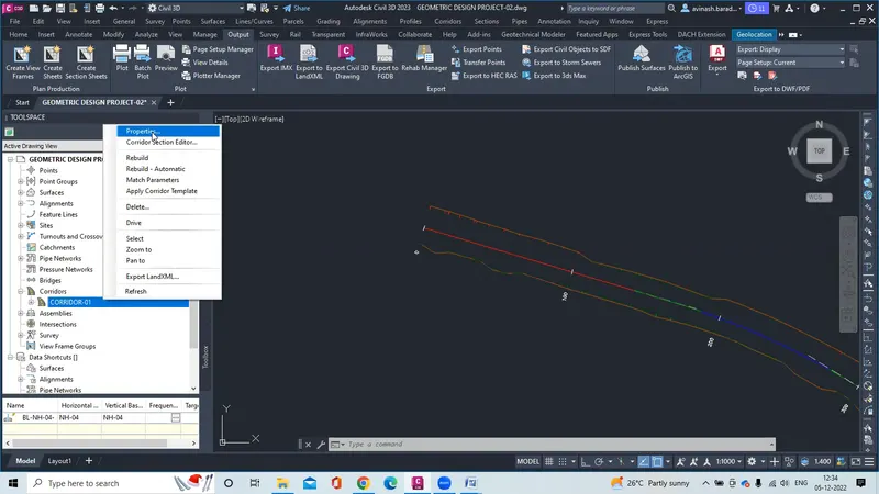
4.Then click on rebuild corridor then the corridor is created and go to corridor properties and change the station length upto which the corridor has to build.
5.Then the corridor is created.
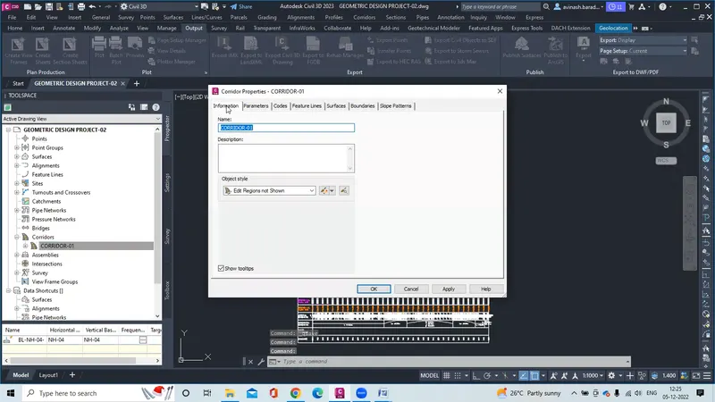
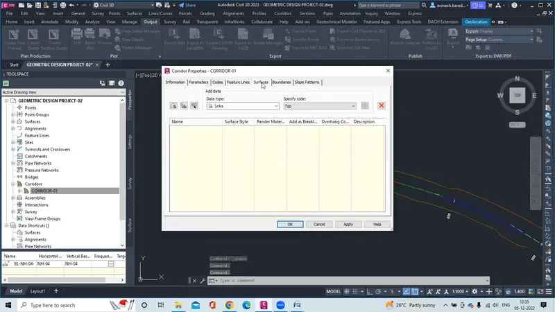
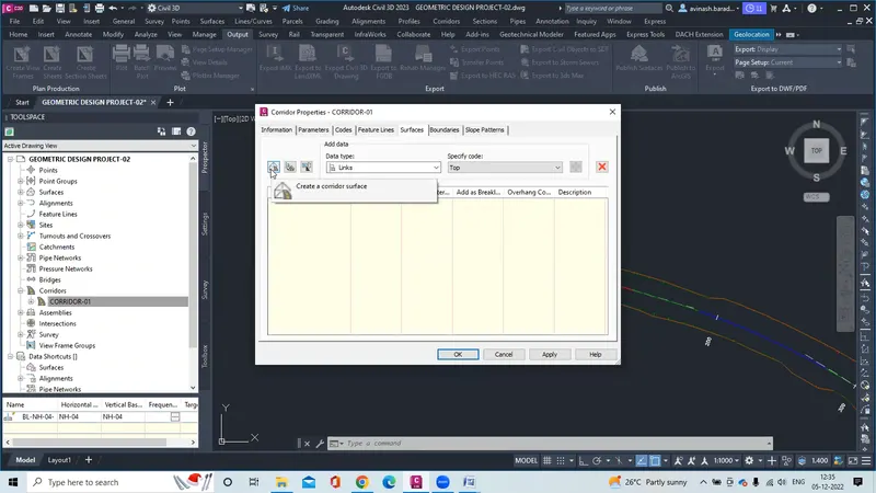
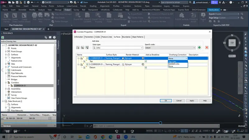
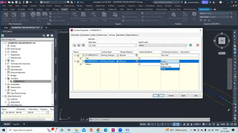
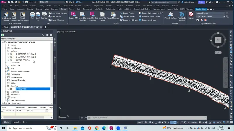
6.Then go to corridor properties and create the surfaces for top and bottom surfaces
5.Section line & detail cross section
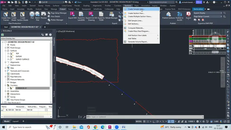
1.In menu bar click on section and select the create sample lines
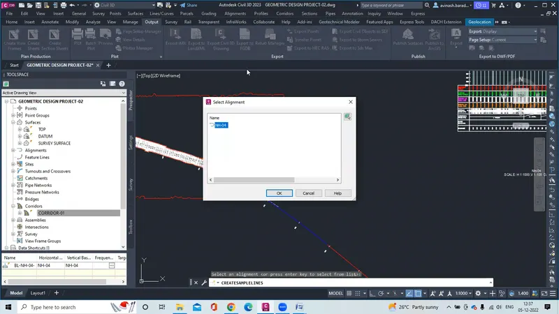
2.Then select the alignment where u want to create sample lines
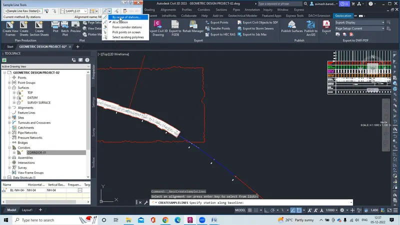
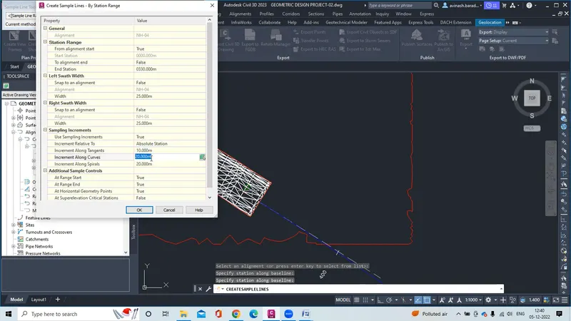
3.Then a panarama window open in that select the sample lines by range of stations
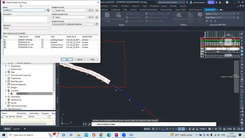
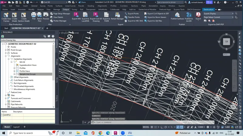
4.Then new tab open set the intervel upto what lengh sample lines to be created then set the range and do necesssary setting and click ok to create the sample lines
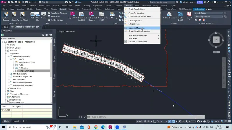
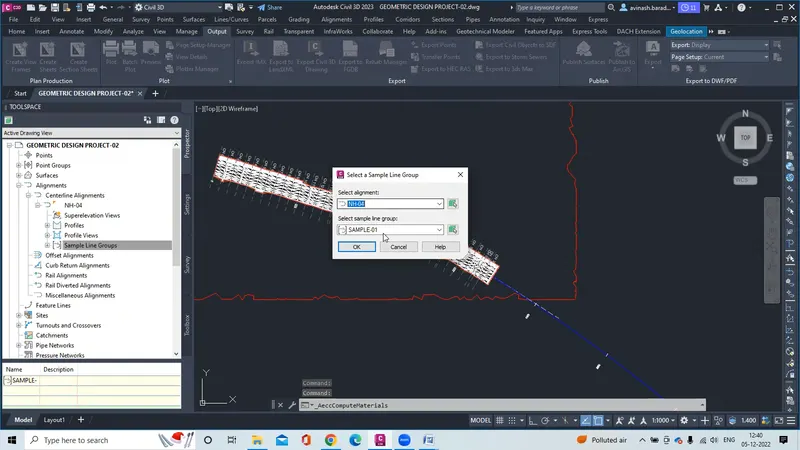
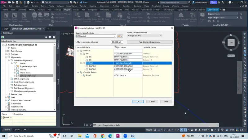
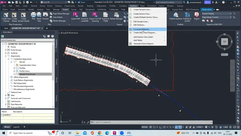
5.Now go to section and select the compute material , then select the alignment and sample lines and click ok
6.Then the surafce data and datum files are selected and click ok
7.Then again go to section and again select compute materials, then aagain select the alignment and sample lines click ok
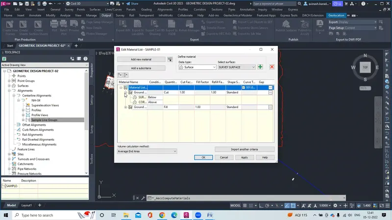
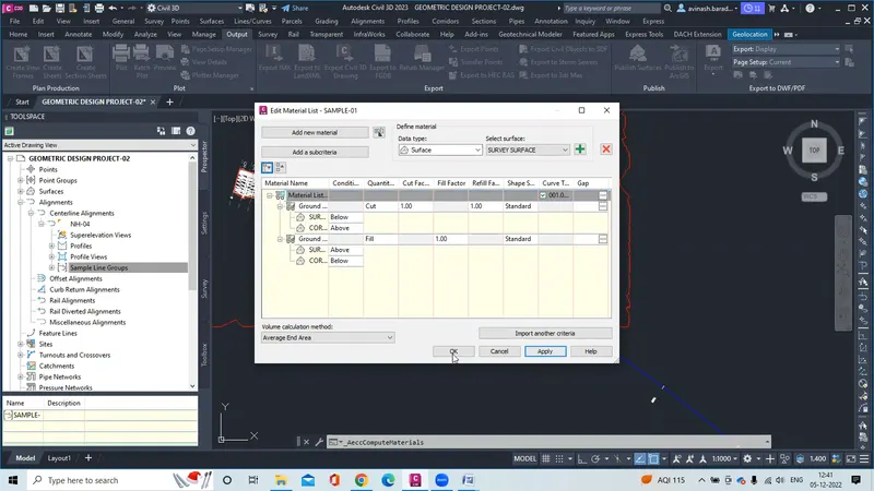
8.Then the material list is available, then click apply and click ok
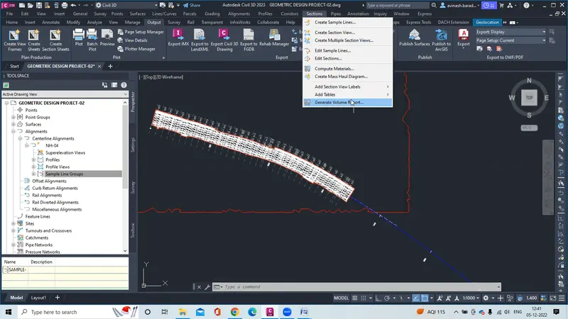
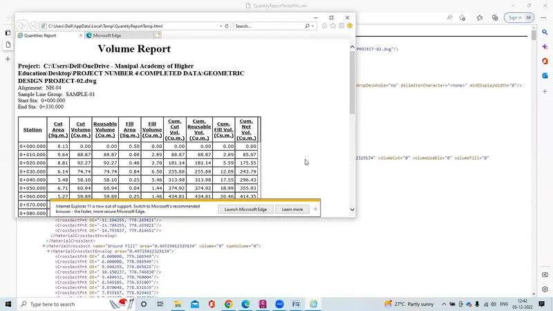
9.Then in section click on generate volume report then file opens and copy the quantity and paste it in the execel sheet
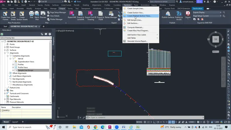
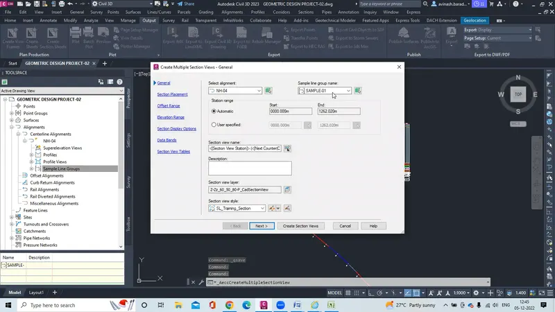
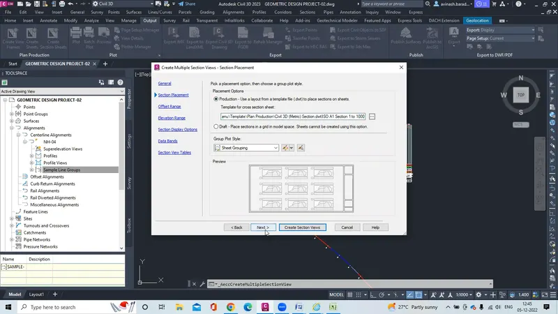
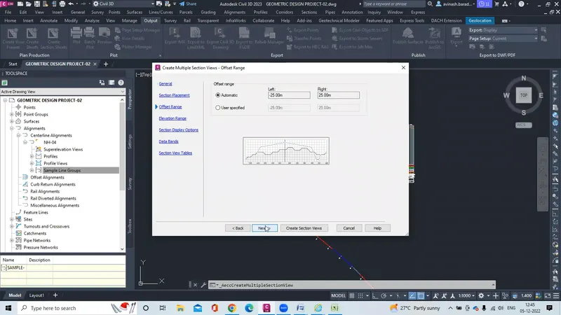
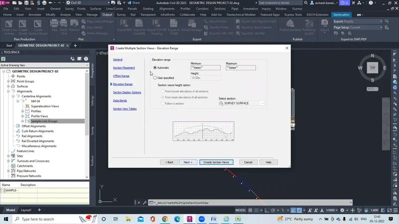
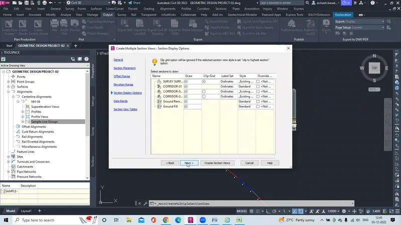
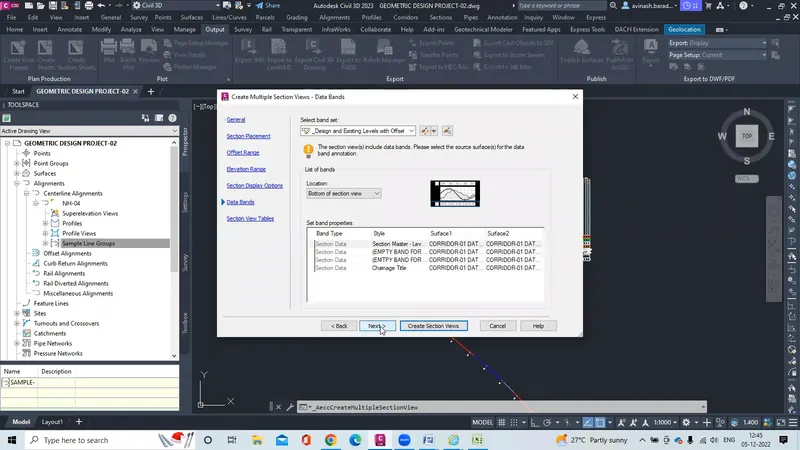
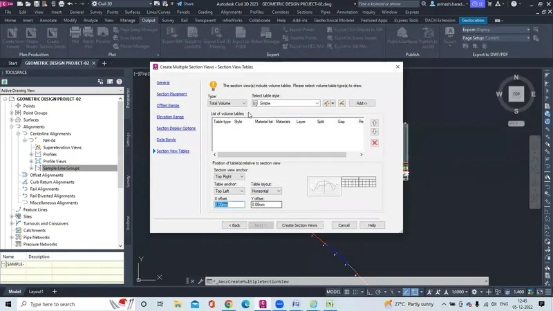
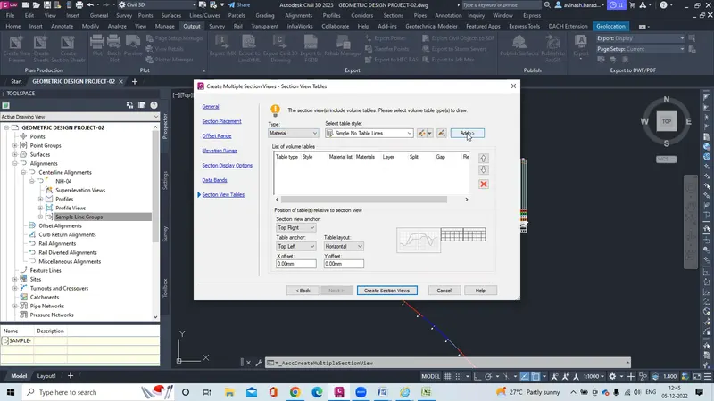
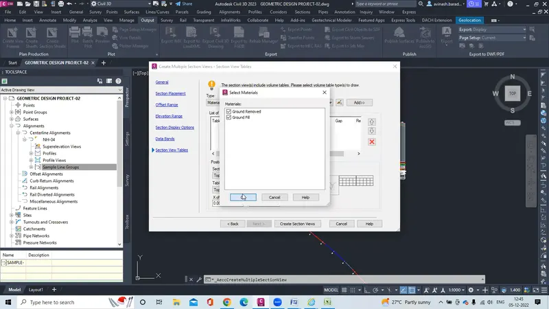
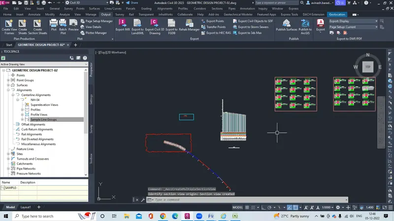
10 Now in sections click on create multiplte section view and set the raange,select alignment and sample group and set the intervel and range of sections then click create section view
11.Now the sections views are created detailed section views