Project - A project on design of road from a given topographic data
Point creation and grouping them with the help of a description.
creating the points :
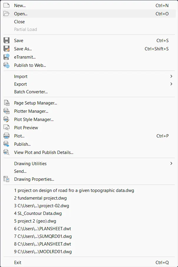
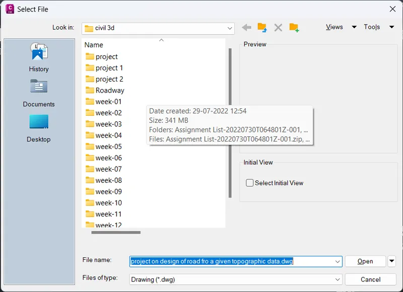
- click file - dialogue box opens - click open - name the file and click ok
- next open the provided file - change the format - go to civil 3d.
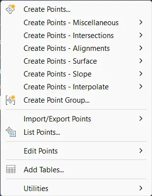
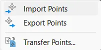
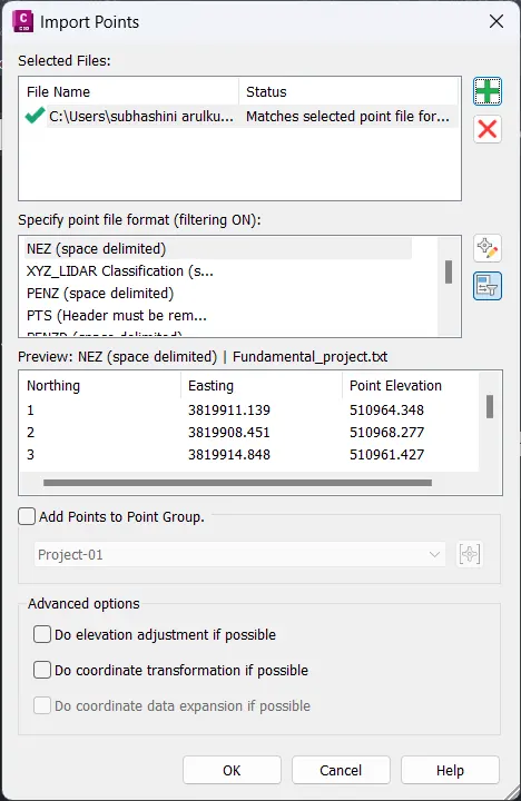
- click points in the ribbon bar- click imports points - select the provided file and click the PNEZD format and click ok
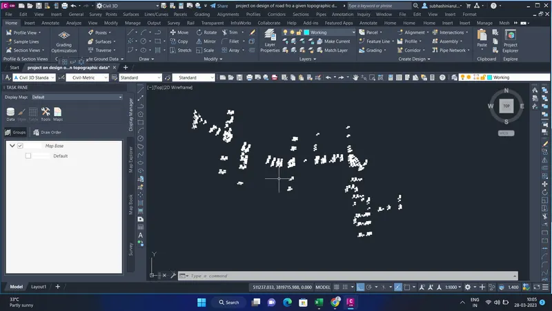
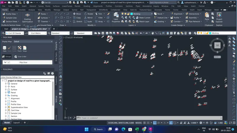
- next the points will be shown in the window
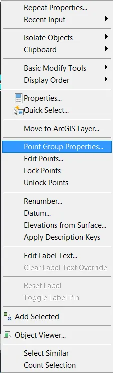
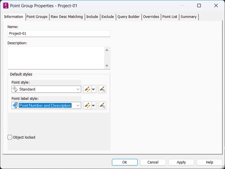
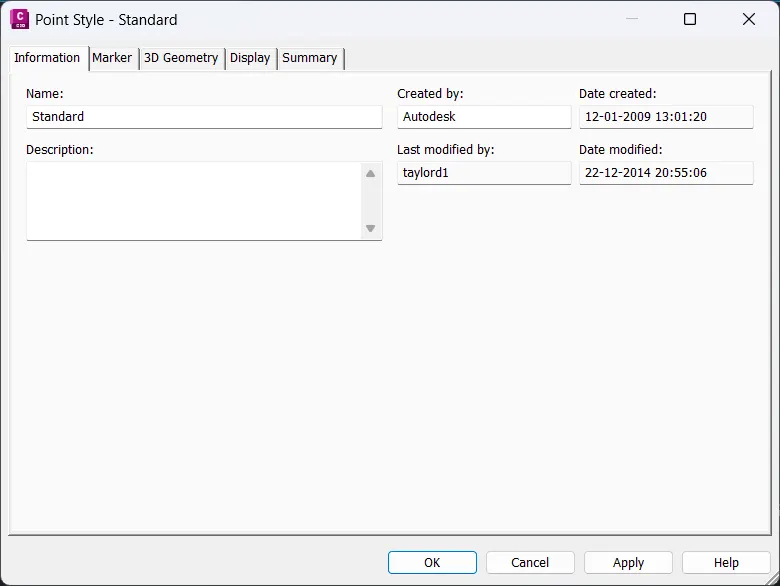
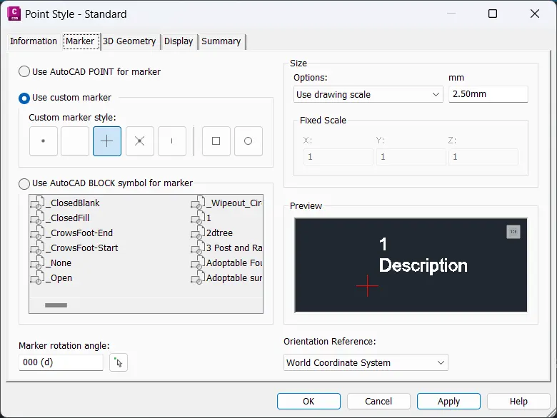
- Net select the points and right click - point group properties- open edit the points style and click ok
Preparation of surface and importance of break lines.
- next, we have to create the surface from the given survey data.
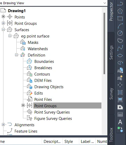
- go to the tool space, click prospector
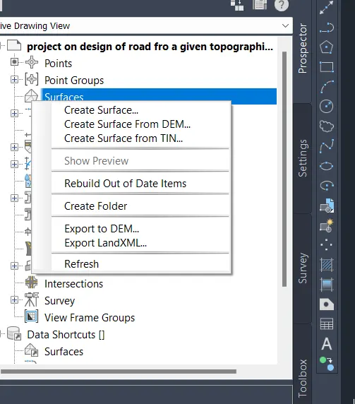
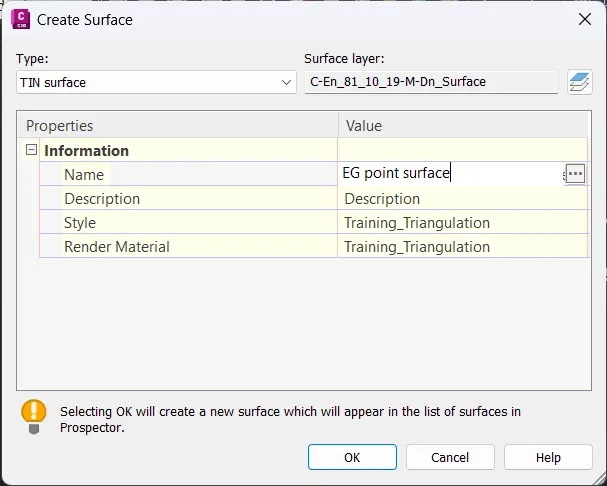
- click surface and right click and the dialog box opens, click create surface and click ok
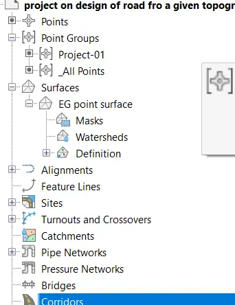
- next we have to click the surface-created file "eg point surface"-definitions-point groups
- click point groups - right click- click add
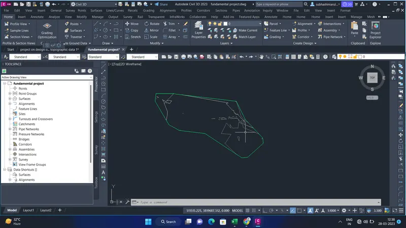
- and click ok. the surface is created.
Horizontal alignment design and adding superelevation.
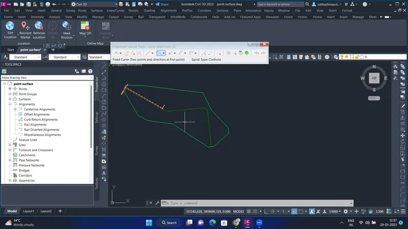
- in the ribbon bar, go to ribbon bar - select alignment
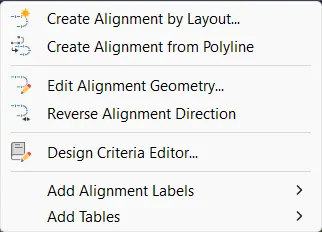
- click alignment-create alignment- select the fixed curve alignment
- next draw the alignment along the road and click ok
superelevation:
- next, we have to create superelevation.
- Get to ribbon bar- superelevation- calculate/edit superelevation
- next, calculate superelevation- enter the lane's width and slope value.
- enter shoulder outside edge value.
- next check mark for automatically- click resolve to overlap and give a finish.
4.Vertical profile design.
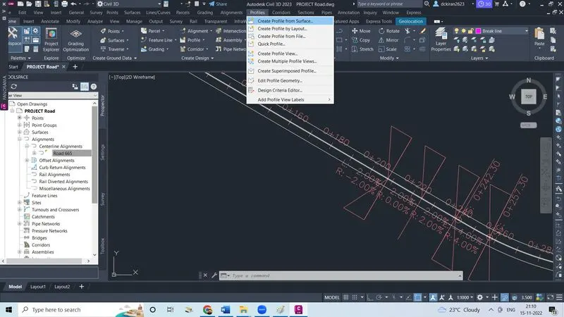
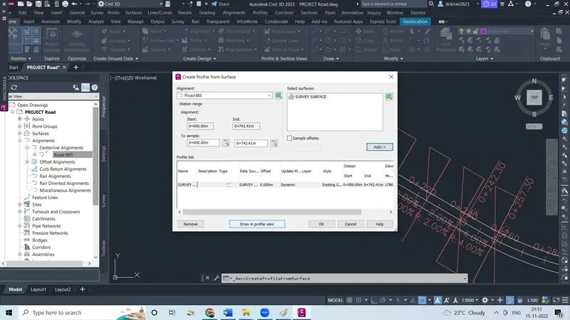
- Now click on create profile from surface
- Select alignment and select surface, Click on add
- Click on draw in profile view
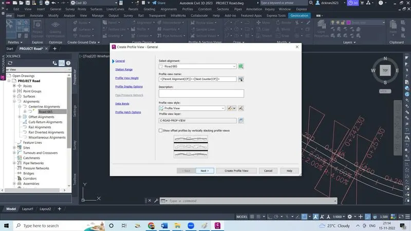
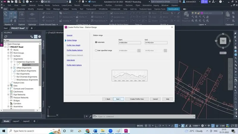
- Select alignment, click next
- Make dot mark on automatic click next
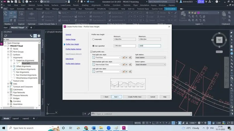
- Make dot mark on userspecified give minimum and maximum height,click next
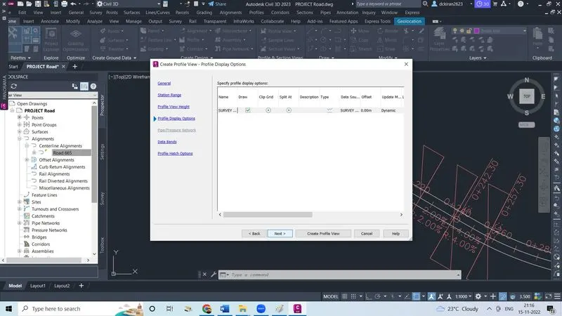
- Click next
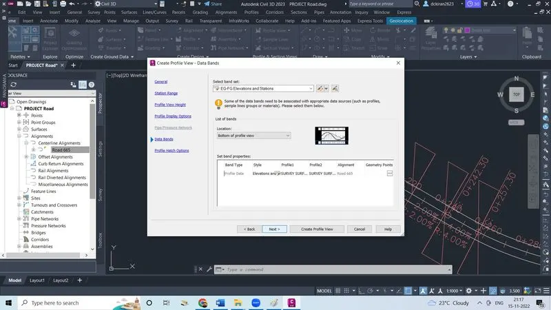
- Select band set, click next
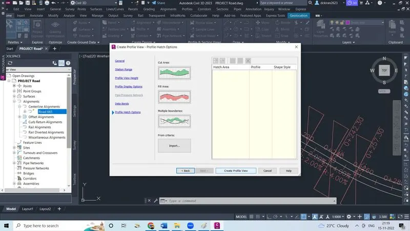
- Click on create profile view
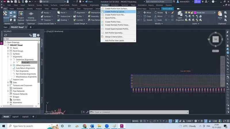
- Click on profile,click on create profile by layout and select profile
- Give name , click ok
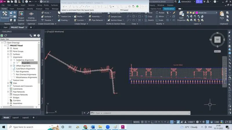
- Select the fixed tangent, draw the line from starting station to end station
- Select free vertical curve(parabola) to give find out the K value
- Select 1st entity, 2nd entity press enter , give the radius like wise do the same procedure for all and findout K value
- Profile view is created
5.Cross section template creation based on proposed conditions.
- After creation of profile now want to create assemblies and subbassemblies to create corridor so
- Click on assembly click on create assembly
- Click ok
- Click on somewhere to create the subbassembly
- Type command 'MT' after type CTRL+F select the objects infiled category/in object type click green mark and go and click on the assembly mark automatically dailogbox will open there we have to select name in preview we want uppercase
- Click on the assembly mark, Click on the toolpalette
- Tool box will open in the lanes section select the"lane from tapered median 1 or 2" again properties box will open
- Click on the mark, if the text sixe big then select the text right click on label properties their we can edit
- If lane text size is big then select and right click, click on the subbassembly properties their we can change
- Now we have to create the shoulder
- Click on the assembly/toolpalet/in the generic/select link width and slope and click on the right lane, then select shoulder and right click/subassembly propertieis/parameter here we can change width of the shoulder and slopeas per TCS click apply and ok
- Now we have do cut and fill so
- Click on the assembly/toolpalet/in the consition/select condition on cut and fill create the cut and fill 1:4 click apply and ok
- Now we have to add the ditch
- Go on the generic/link width and slope and click on the cut and fill line/give slope and width click apply and ok
- Go on the condition section/select condition cut and fill
- Same thing mirror all right sub assemblies to the leftside
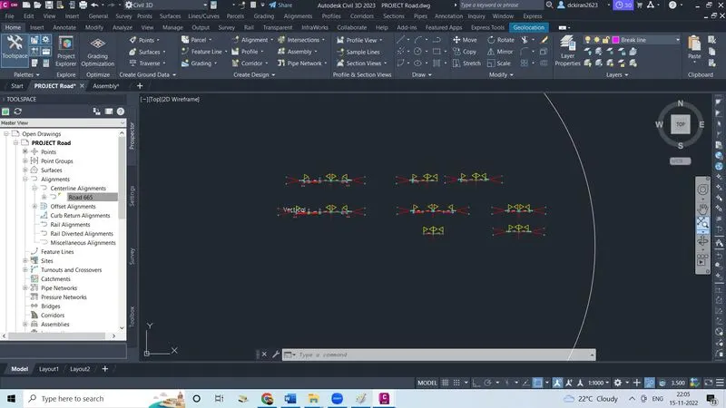
- Then assembly is created
6.Corridor modelling and extraction of finished surfaces.
- After creating assembly lets create a corridor
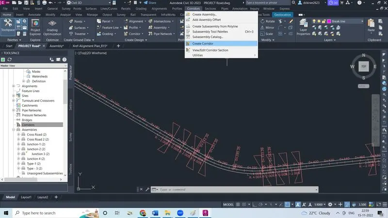
- Click on corridor
- Click on create corridor
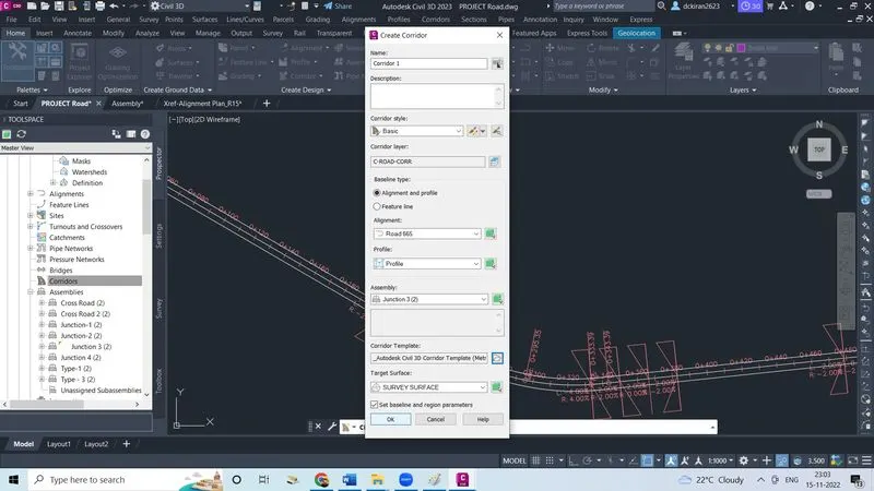
- Give the name
- Select the alignment as Road 665
- Select the profile
- Selct the assembly as junction3(2)
- Select the target surface as survey surface
- Select the coridor template as metric
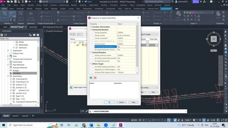
- Set the frequency and click ok
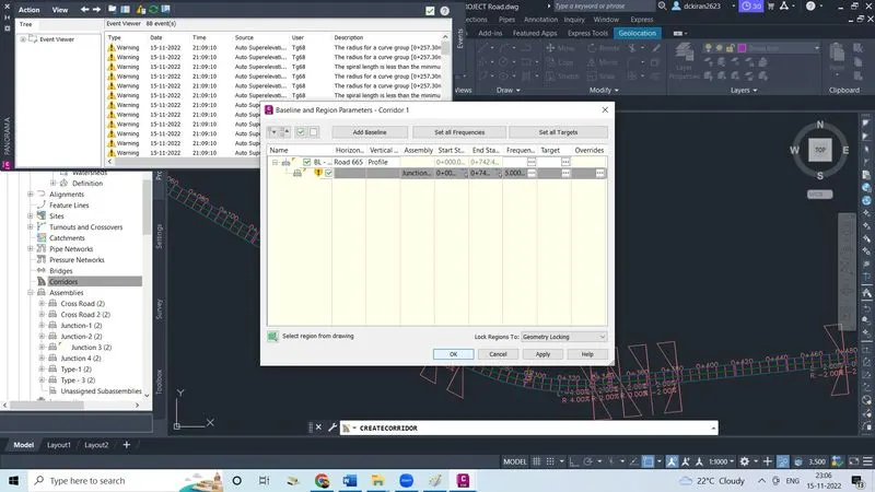
- Set the target, select the surface
- Click apply and ok
- Corridor is created
7.Cross sections production based on corridor modeling.
- Before creating a cross-section view 1st we have to create sample lines so
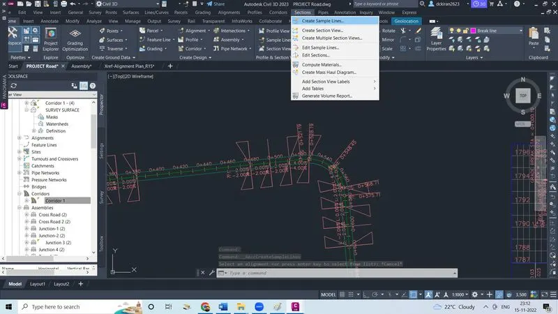
- Click on section
- Click on create sample lines
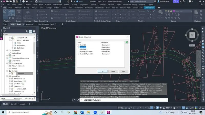
- Select an alignment and press enter and then
- Select on alignment and click ok
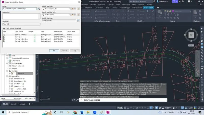
- Click ok in sample line group press enter
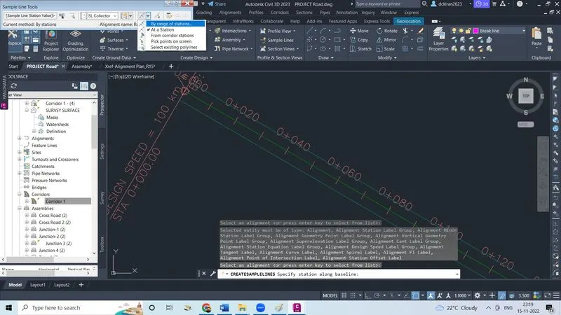
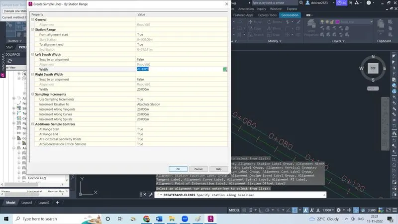
- In sample line tool box select "by range of stations"
- Make true for at range start, range end, at horizontal geometry points, at superelevation critical stations
- Click ok sample lines are created
- Now delete the unwanted sample lines which we won't need
- Now we have to create crossection view so
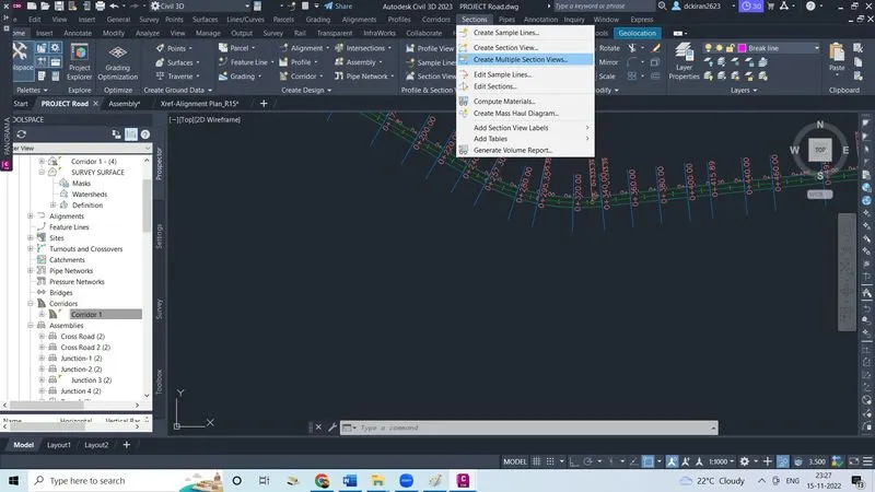
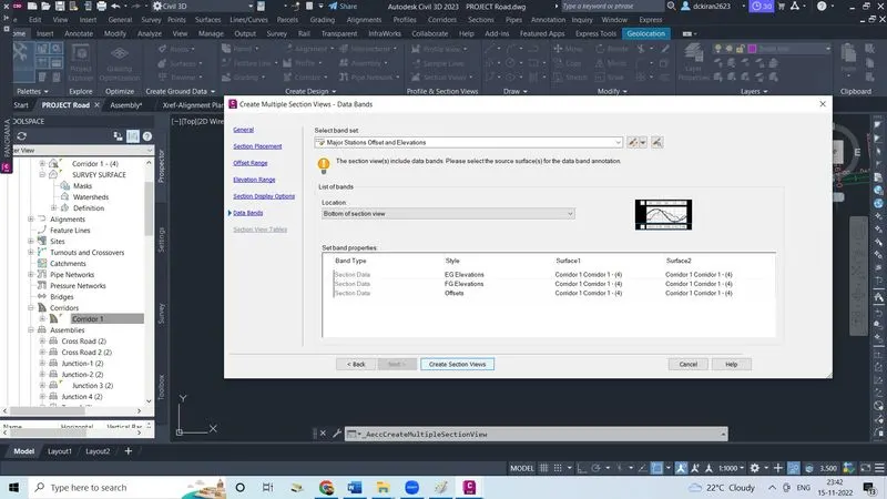
- Click on section, click on create multiple section views
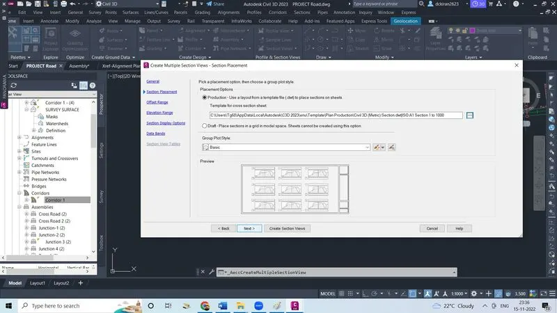
- Select alignment and give the section view name,then
- Click next
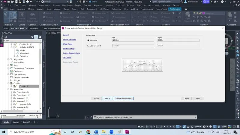
- Make dot mark on the user specified and give the height select the section click next
- Click next
- Select the band set
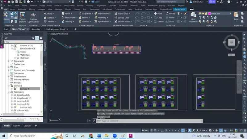
- Click on create section view
8.Earthwork quantities and material quantities takeoff.
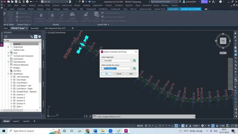
- Select one sample line then one ribbon will reflect in that ,click on compute matiral after that
- Select the alignment and select sample line group click ok
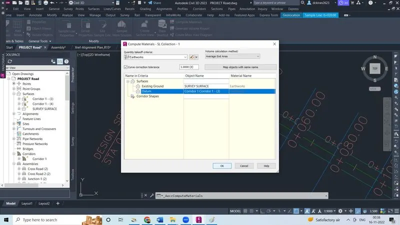
- Do first select the quantity takeoff criteria is earthwork
- For existing ground select the object name as survey surface and datum as corridor 1 corridor 1
- Click ok , it will take some time to compute
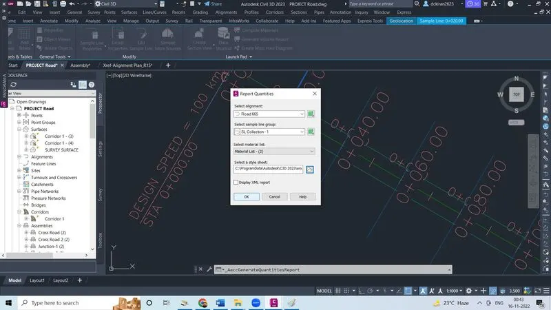
- Now select one sample line click on the generate valume report. because we want quantity volume report one quantity box will open in that select an alignment, select the sample line group
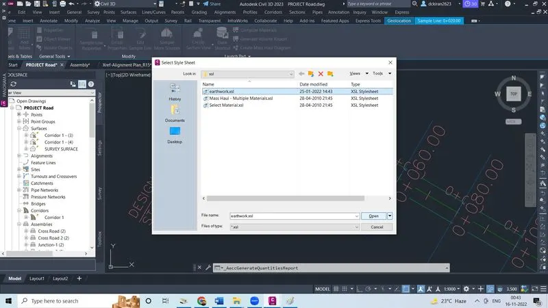
- Select the style sheet, click on that image, select the earthwork.xsl in the file manger loaction click open
- Make check mark on display xml report
- Click ok
- Then volume sheet is created for fill and cut quantites
- Again click on the compute matrial and select alignment and sample line gruop click ok
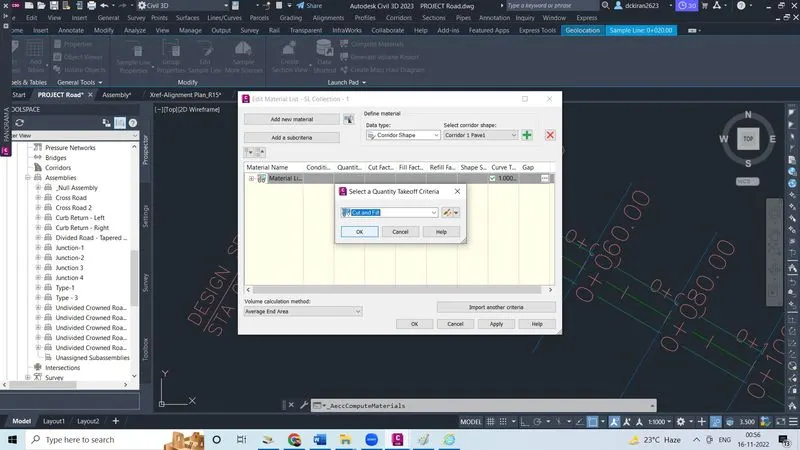
- Now select another data type as corridor shape
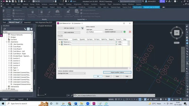
- Click on import another criteria
- Select the quantites takeoff criteria cut and fill Click ok, one dailogbox will open it will ask which is required for that, so for criteria give a proper object name
- For EG give a object name as survey surface for datum give object name as corridor 1 corridor 1 and click ok
- Like wise do the same procedure for all the earthwork quantites like pavement,ashphalt,cut and fill ,kerb..etc and get the volume of quantites of each one