Project 2
1. Complete a project based on all previous lectures.
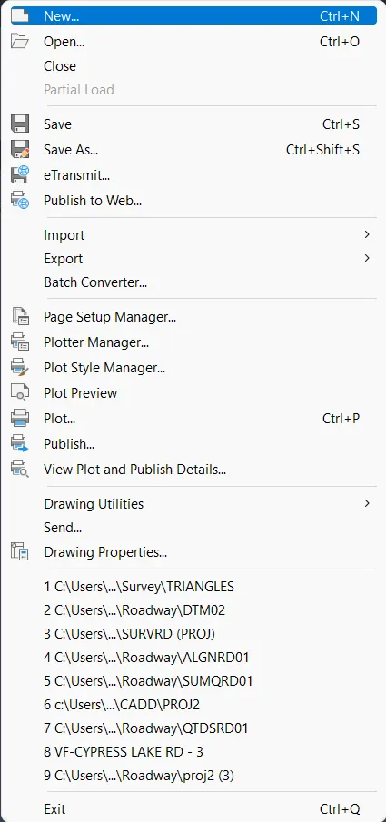
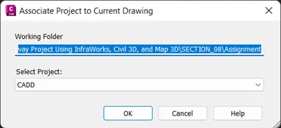
step 1: Create a file
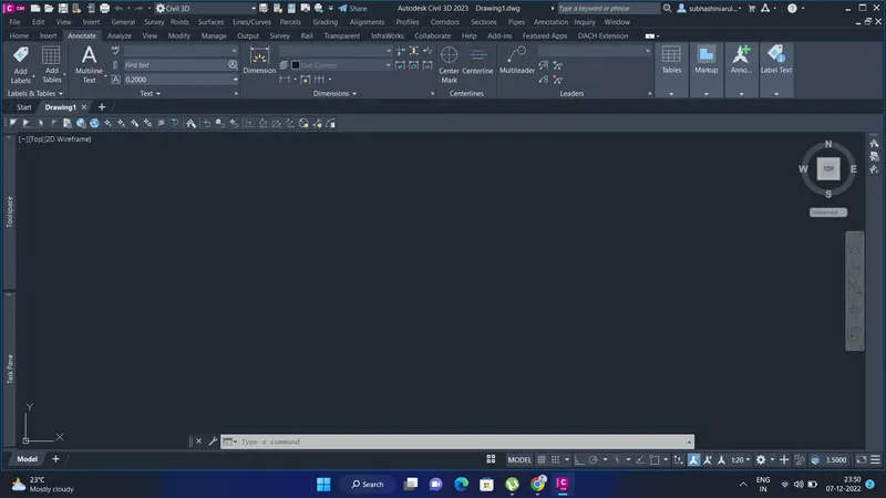
- the new file is opened
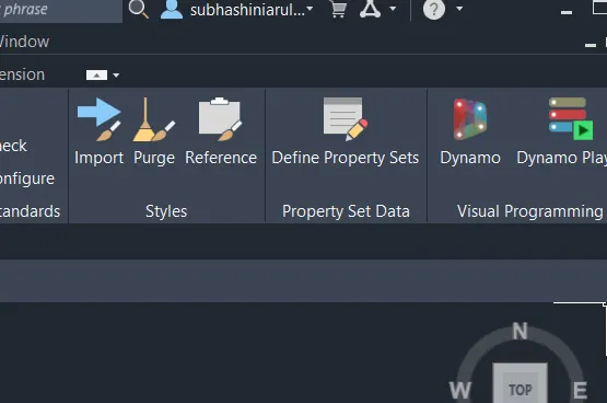
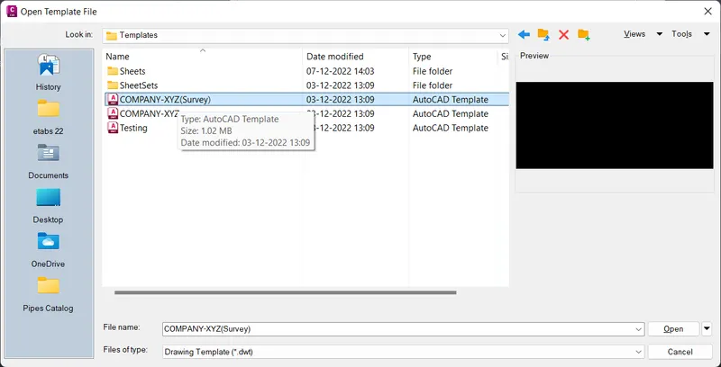
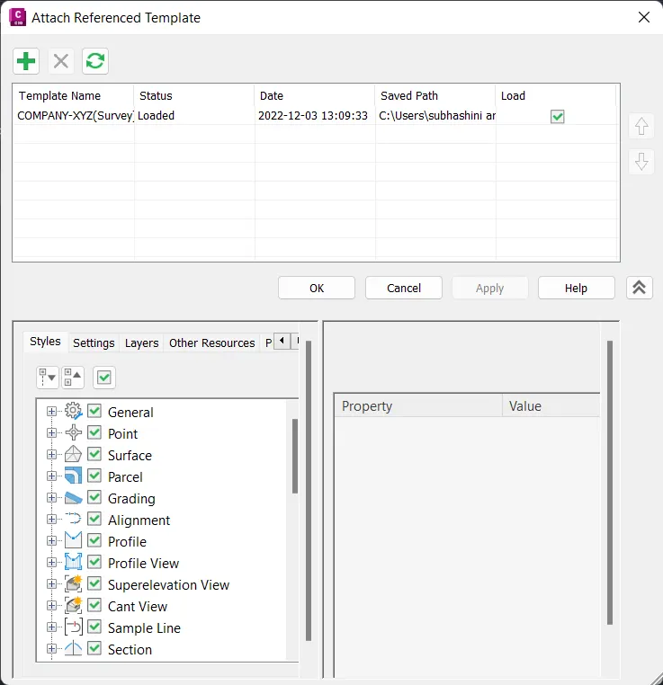
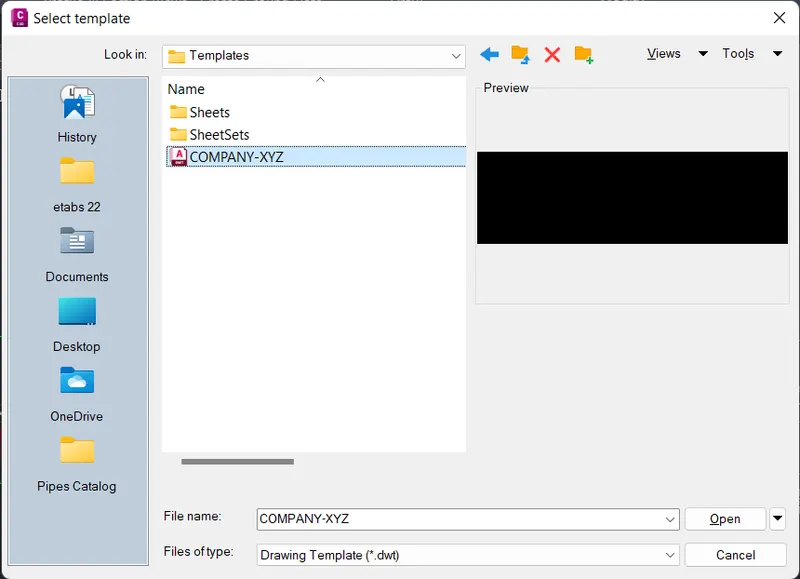
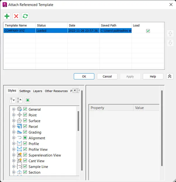
- go to the home tab click on template reference add the company template provided.
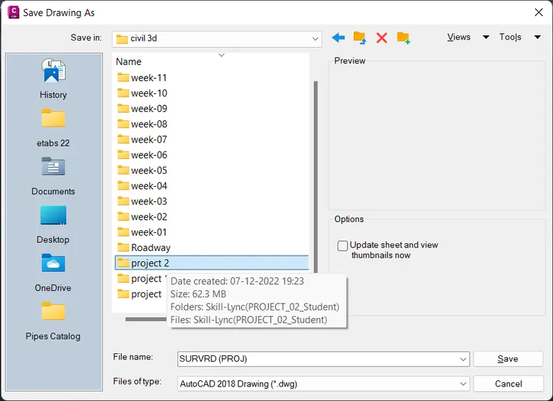
- add the company template to the newly opened file and then save the file
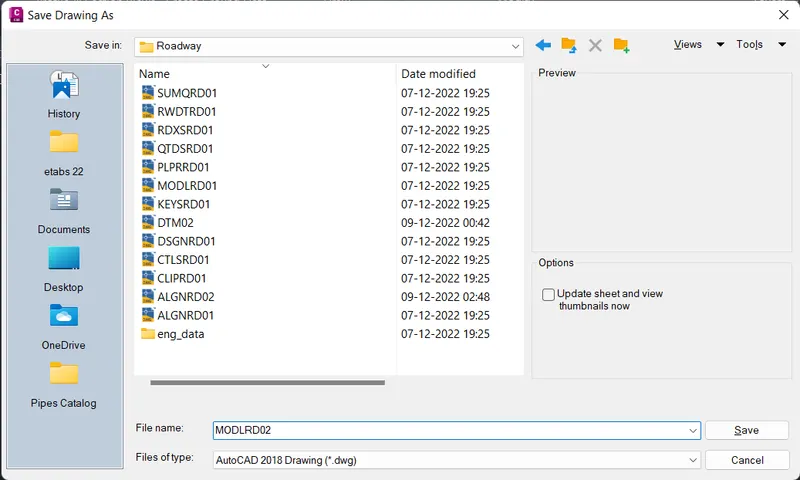
- name it as {SURVRD(PROJ)}now the file is created

step:2 creating description key set
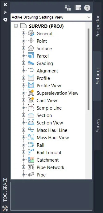
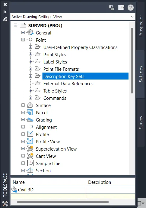
- go to tool space and click setting
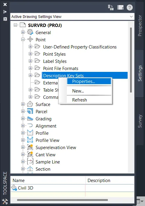
- Click points and go to description key sets
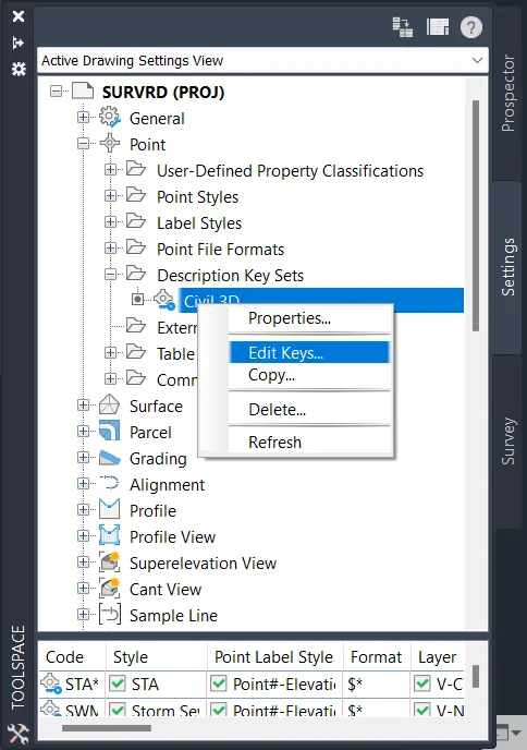
- and then select and right-click the civil 3d
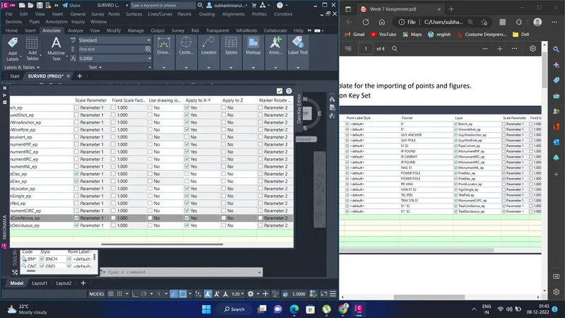
- PANORAMA table will open, and add all the data to it as per the assignment pdf and click ok
- description key set is now prepared.
step:3 FIGURE PREFIX DATABASE
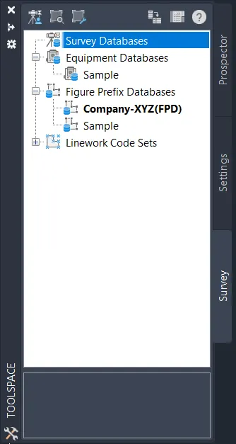
- now in the [SURVRDO (PROJ)], go to tool space /survey/
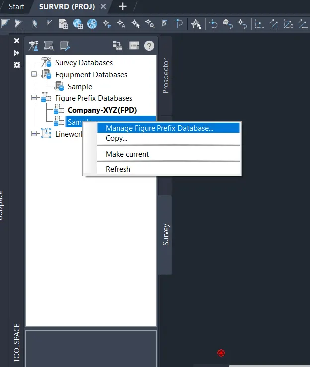
- Click on the manage figure prefix database, click it another thing opens and click on the sample as shown in the figure
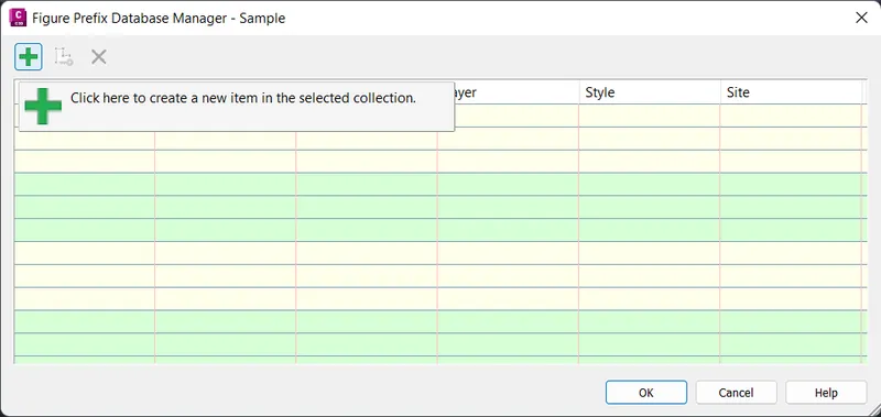
- right-click the dialog box opens for manage the figure database of the sample
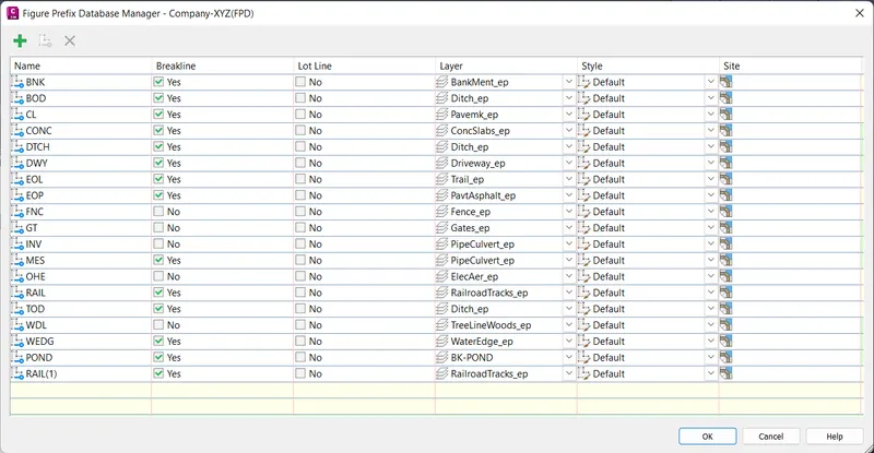
- Click on the plus sign and import the data
STEP 4: SURVEY THE DATABASE
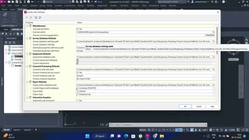
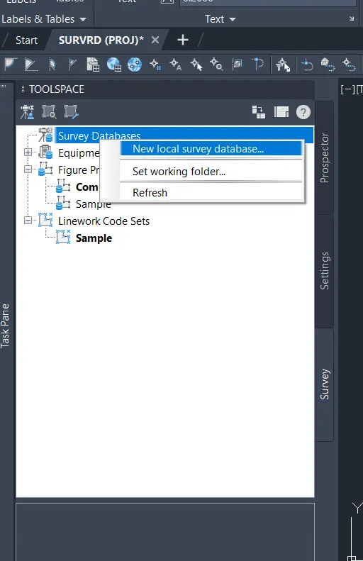
- go to the survey database and right-click a dialog box that opens
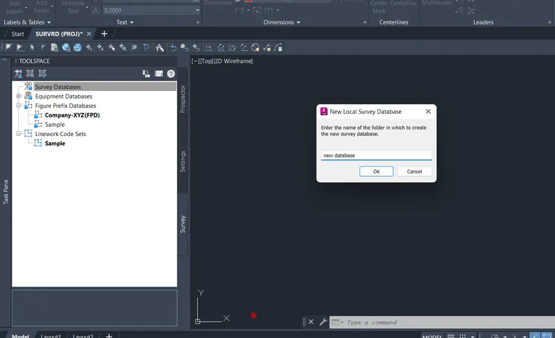
- click "new local survey database "another dialog box opens, name it "new database"
- and click ok
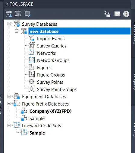
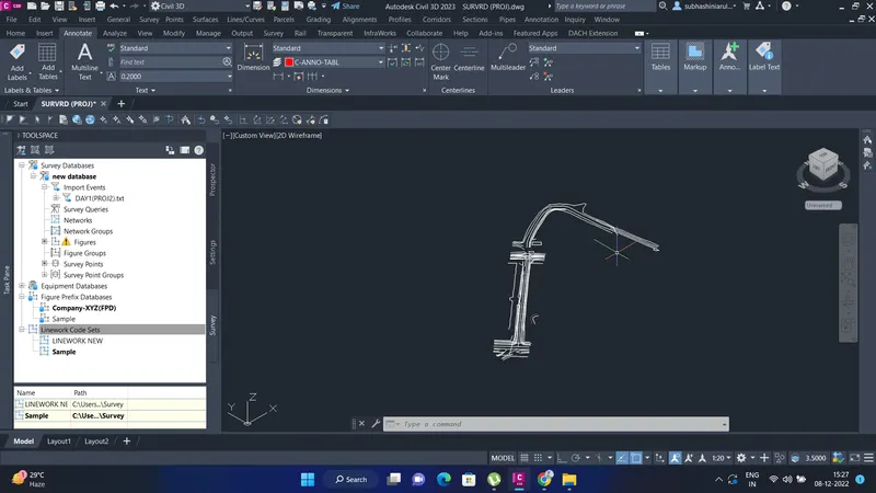
- now the new database is shown in the survey database
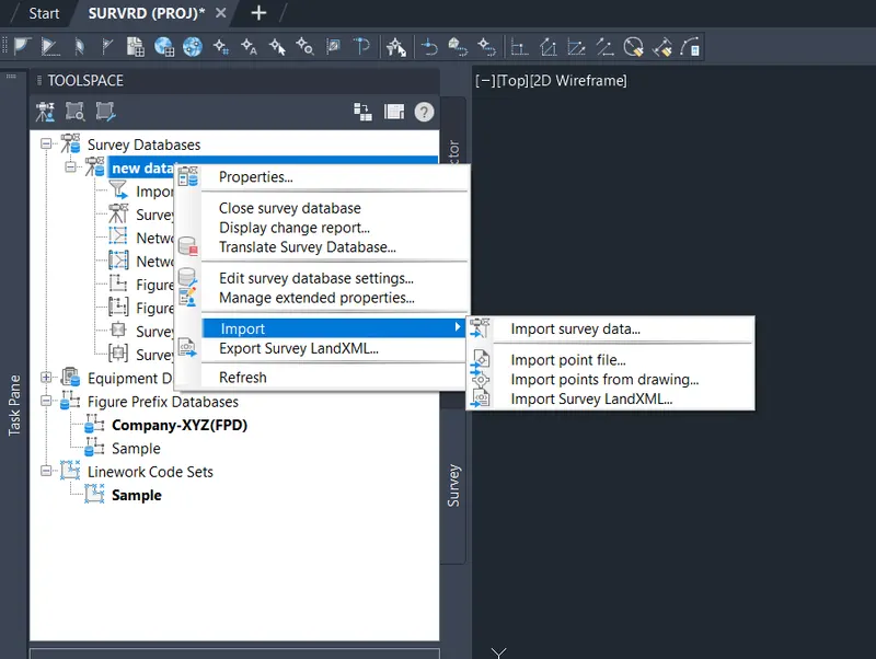
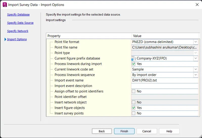
- next click on the new database, and select import.
- in the import, many options open such as import survey data, import point file, import points from drawing, import survey land XML
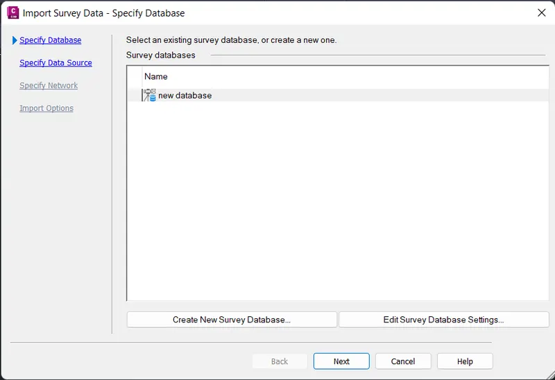
- among that select the import survey data
- an import survey data-specific database dialog box opens
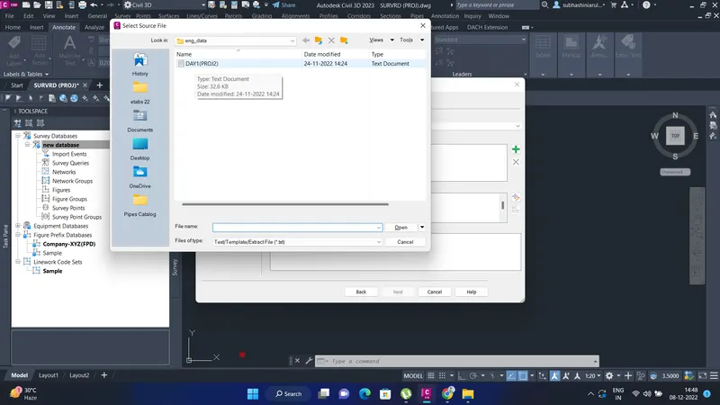
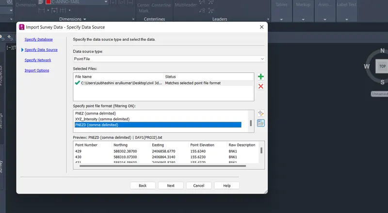
- in that select point file and click ok plus sign and add (day1(PROJ2).txt file and click ok
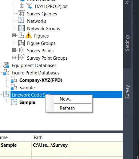
- Go to survey database/linework code sets/
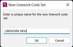
- right click linework code sets, click new and name it as " linework new"
- and click ok
STEP:5 importing land XML file
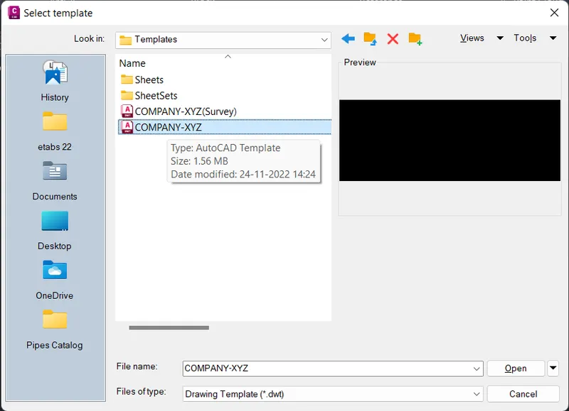
- New file open with company template -XYZ (survey)
- save it as "DTM02"
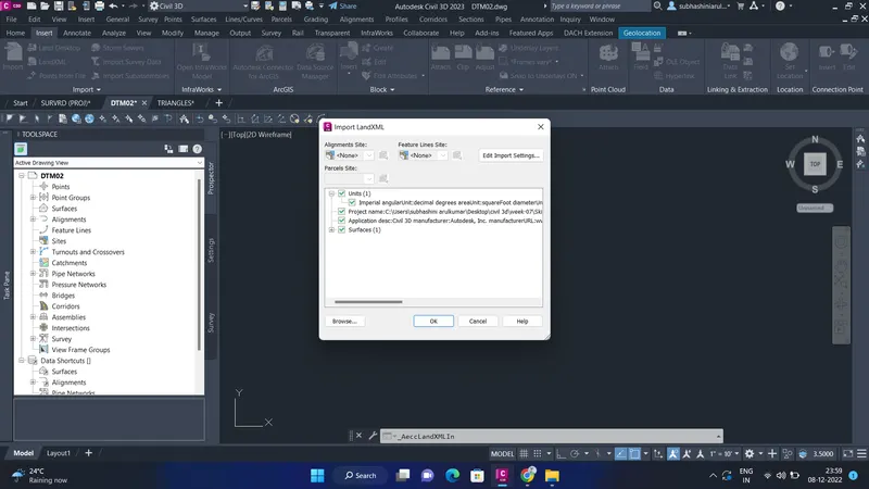
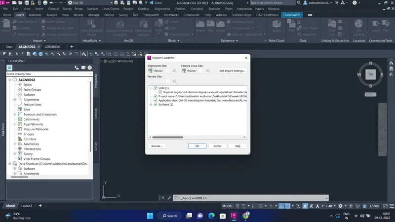
- next, we have to import the land XML file
- open triangle files from assignment 7
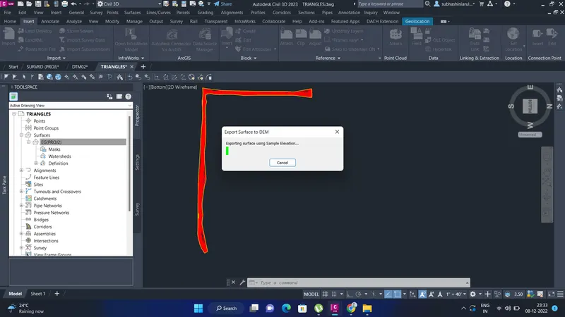
- go to tool space, click surface and select export XML
- the exporting will happen, then click ok dialog boxes open again click ok
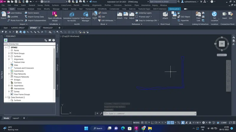
- the XML is imported.
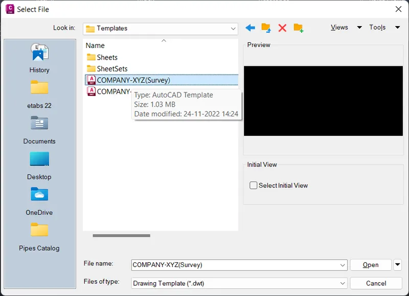
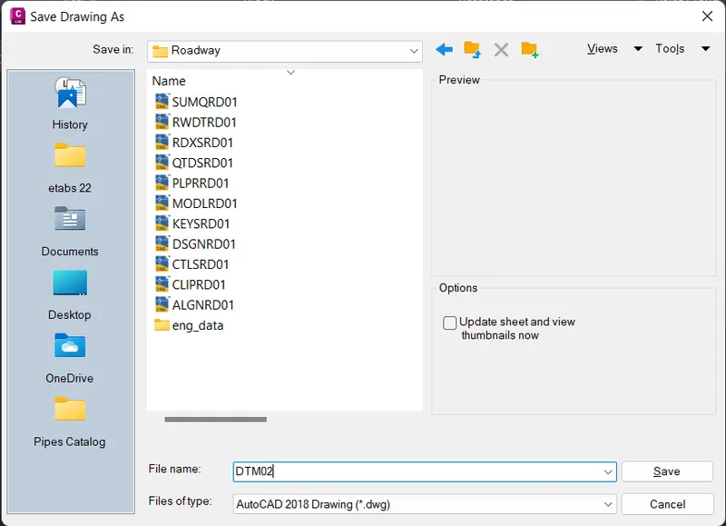
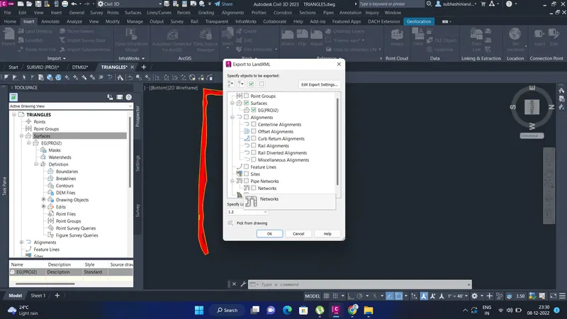
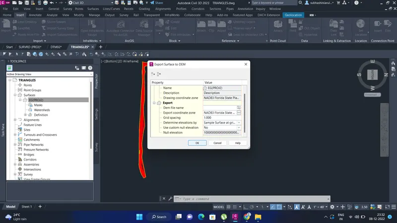
step:6 creating alignment
- Click the new file with the company template ("Company XYZ") and save it as ALGNRD02.dwg
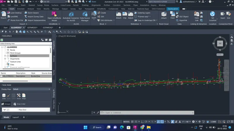
- next, go to the surface and click land export XML from (GDTMRD02)
- Next type "xref" to import the (TOPOD01) topography file into the (ALGNRD01) file
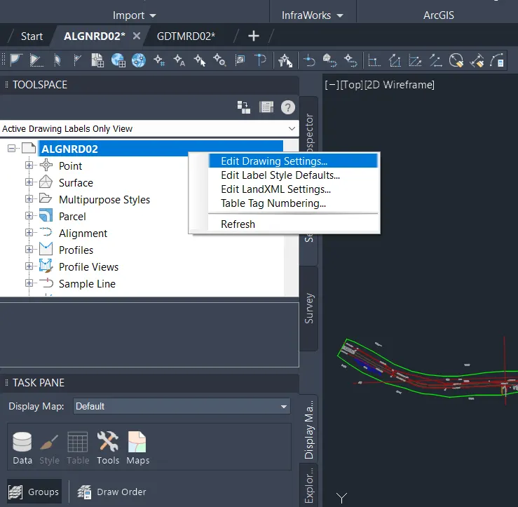
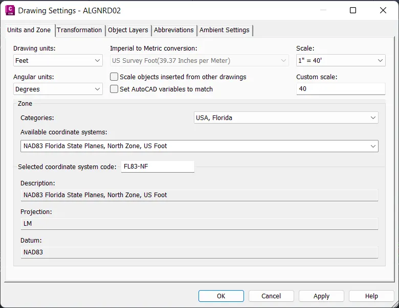
- next ALGNRD01, go to settings in tool space click edit drawing and select coordinate as"FL83-NF"
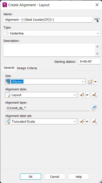
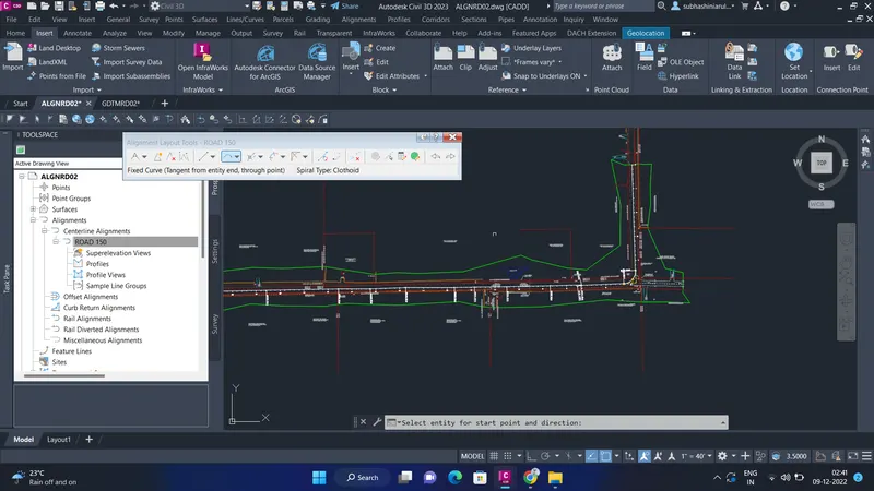
- go to the ribbon bar and click alignment /create alignment by layout.
- create alignment dialog box opens and creates the alignment [road150]

step 7: creating superelevation
- next, create superelevation
- Click on the alignment and select edit superelevation
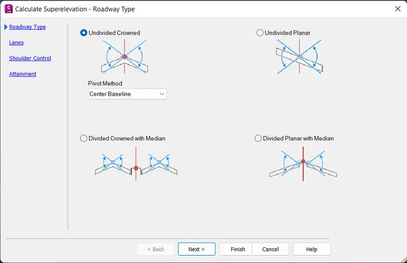
- calculate superelevation -roadway type dialog opens
- in roadway type select undivided crowned, click next
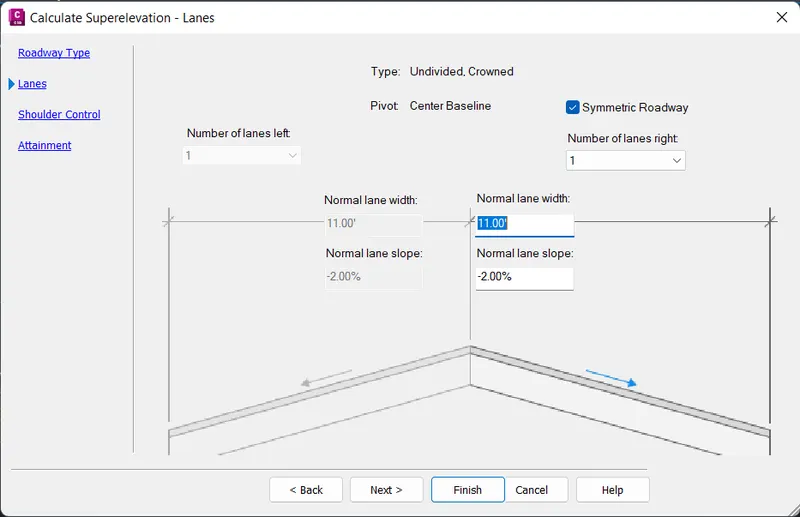
- next in lanes normal lanes as width '11' and for lane slope '-2%' and click next
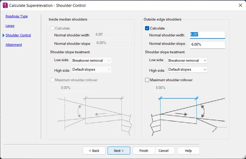
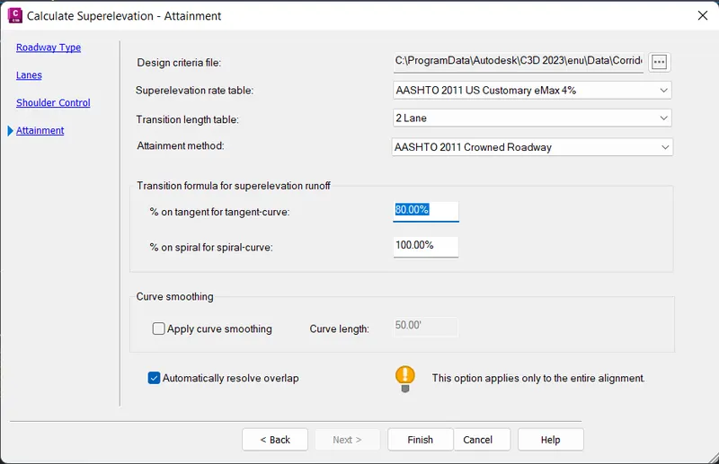
- in shoulder control, assign normal shoulder width as 6.00 and normal shoulder width - 6.00% click next and f=click finish
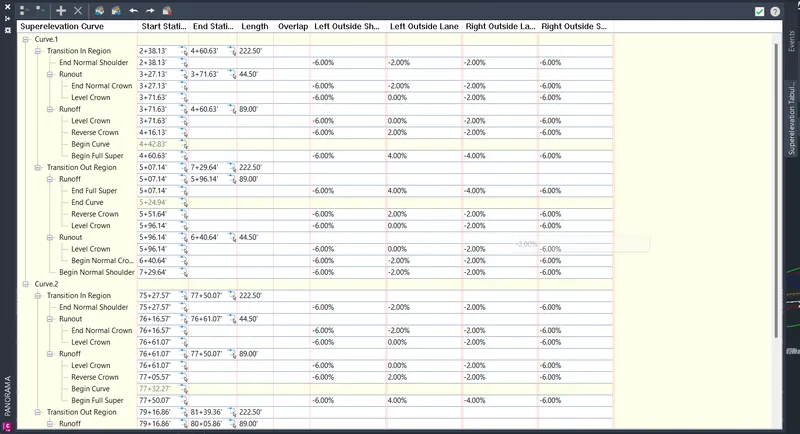
- now superelevation is calaculted.
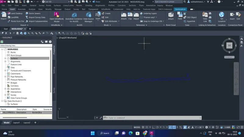
step:8 creating the "MOLDLRD" file
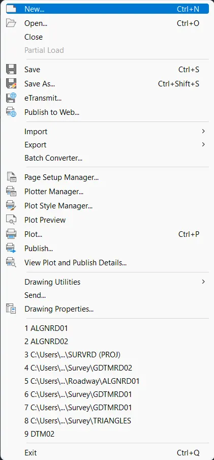
- Click the new file with the company template ("Company XYZ") and save it as MOLDLRD.dwG
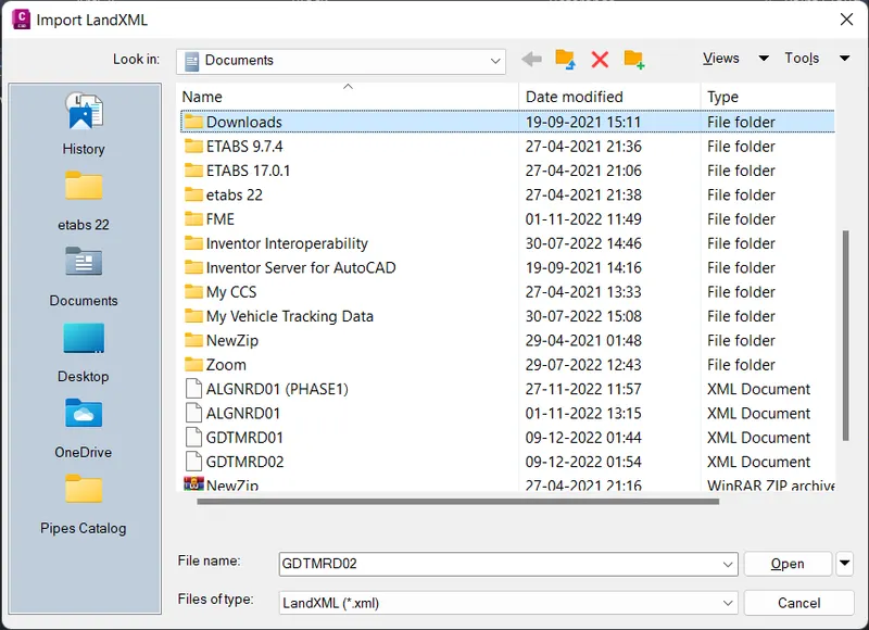
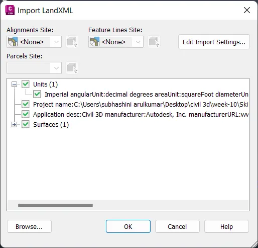
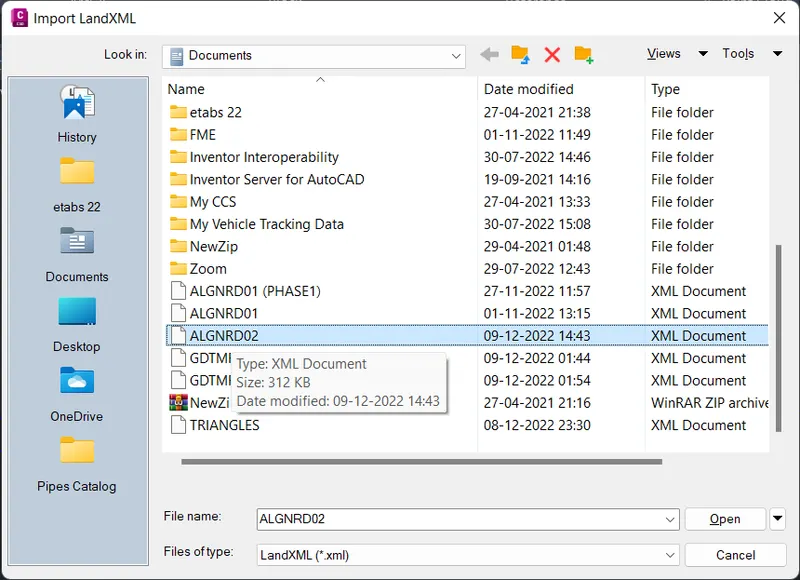
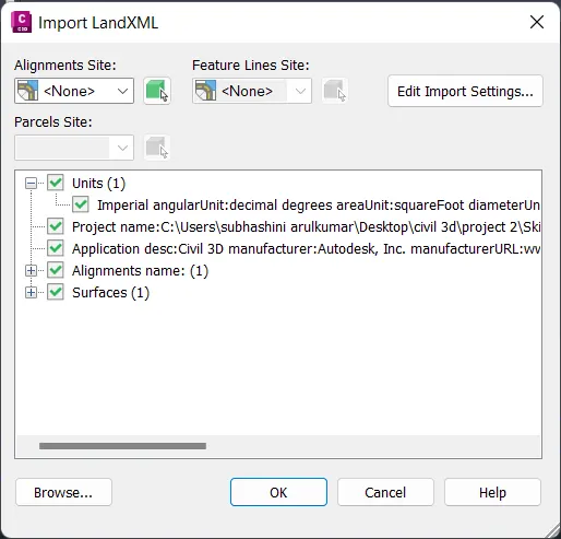
- next import land XML of the GDTMRD02 file and click ok
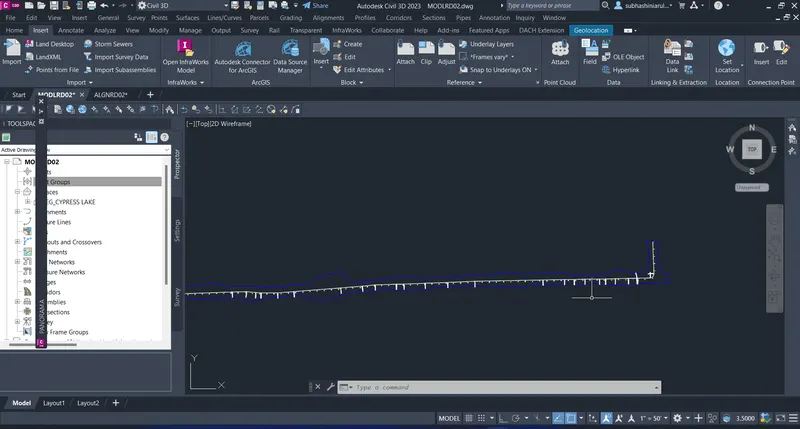
- next, import the ALGNRD02 file and click ok
- now the MOLDLRD file is created with all imports
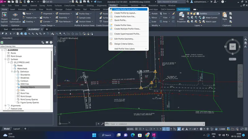
step 9: Create a profile view
- in the toolbar, click a profile
- right profiles and select create profile view
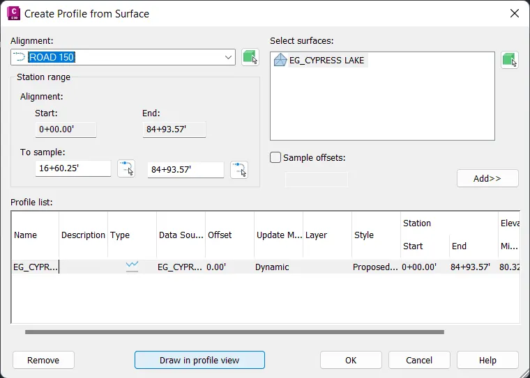
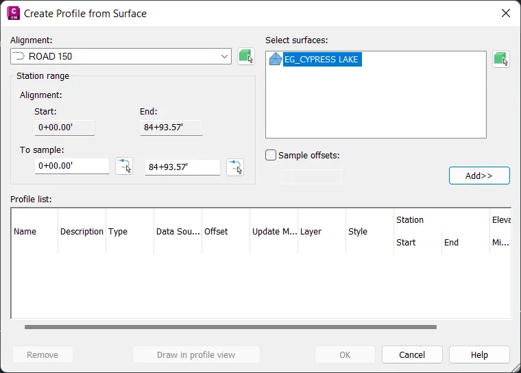
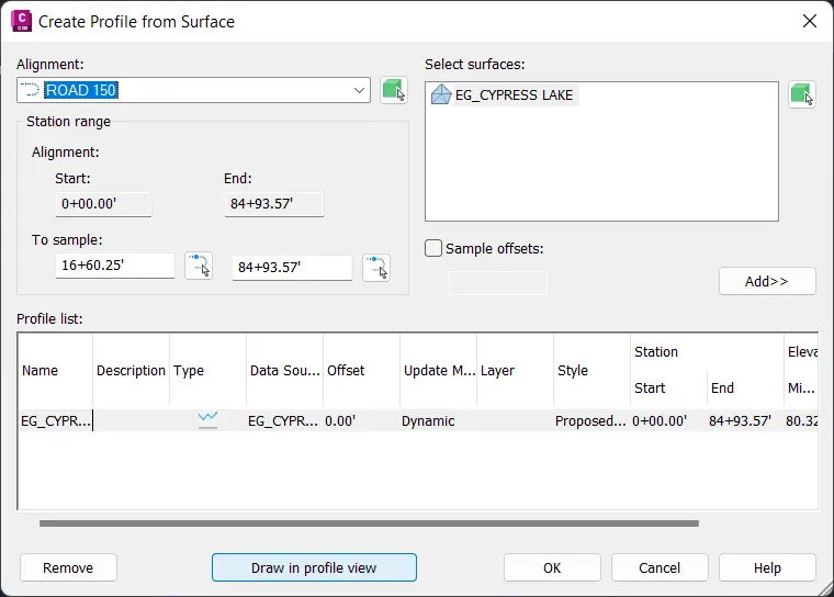
- create a profile from the surface dialog box opens
- select the surface and add it to the profile list
- set all the data one by one and click create profile view
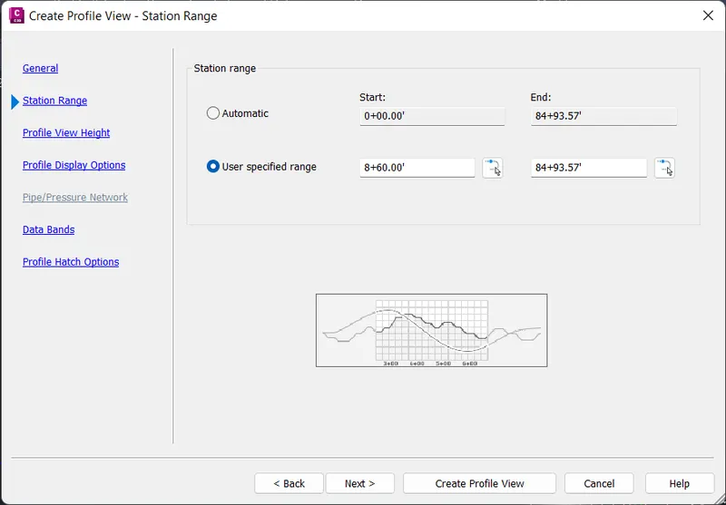
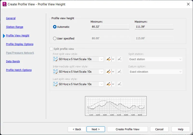
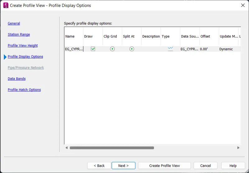
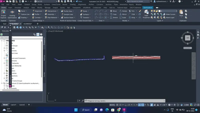
step:10 creating assemblies and subassemblies
- Go to the alignment file that was created
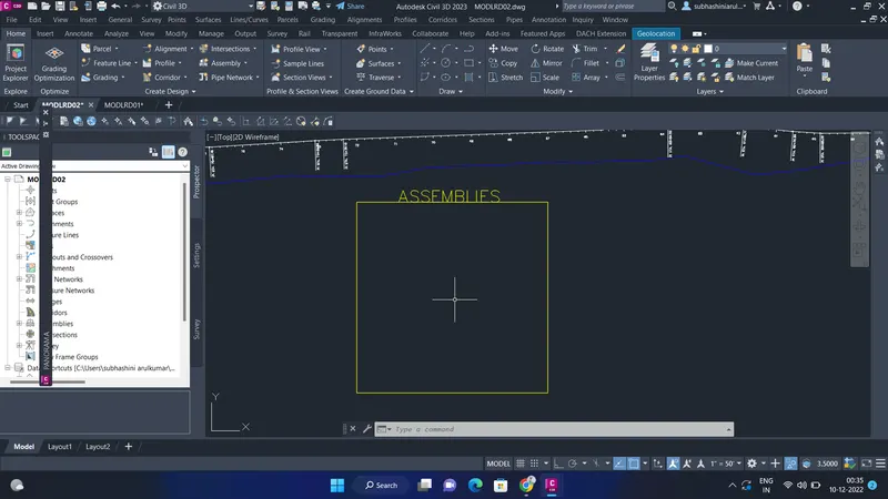
- next, draw a rectangle by typing the "rec" command
- next type the "MTEXT" dialog box opens, draw a rectangle above the previously created rectangle
- then type "ASSEMBLE" and hit ok
- the selected things are created assemblies (shown in the figure)
- Go to the home tab and click assembly and then click create assembly
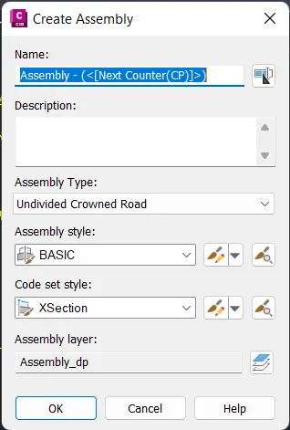
- Next assembly dialog boxes open, the name is typed and assembly styles are selected and click ok
- Next, go to tool plates and select lane superelevationAOR, give the name of the subassembly
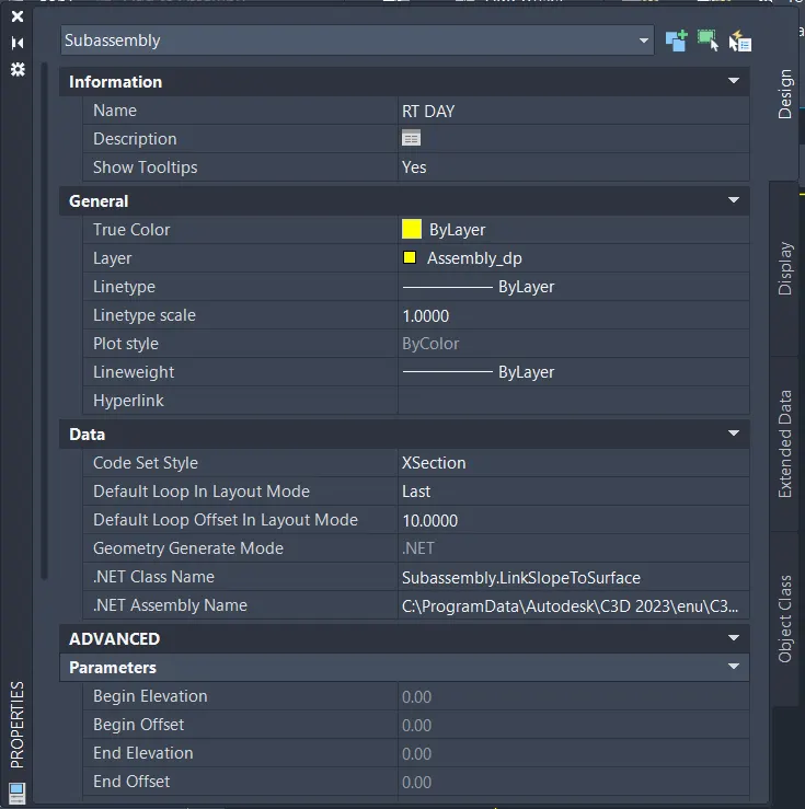
- Click the subassembly/commands/create subassembly and click it, the dialogue box opens as shown below ,check the requirements and click ok
- next, go to condition select conditional horizontal target and click
- after selecting go to properties and the select target is not found as an option in the properties ,name it "RT_STD".
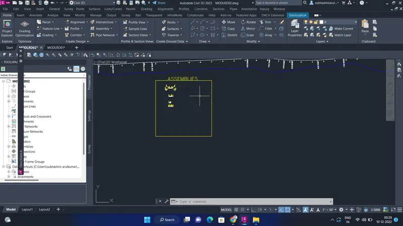
- created things are shown below
- mirror copied the thing that created

step 11: creating a corridor
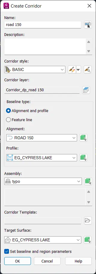
- next is creating corridor, go to the home tab, select corridor, and click create a corridor
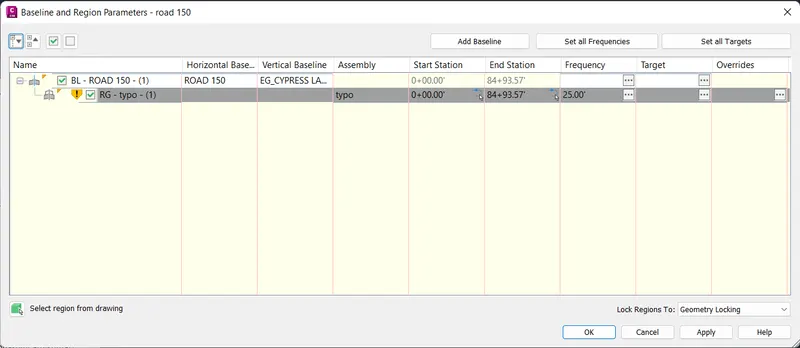
- check the requirements
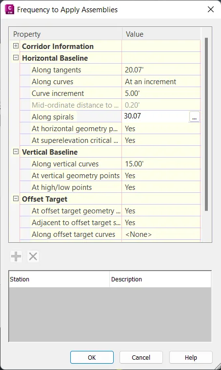
- change the along vertical curves for the better view
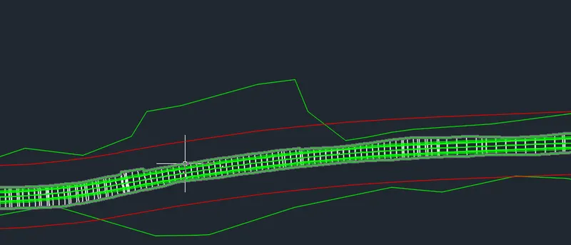
- and click ok the corridor is created
step:12 creating intersection
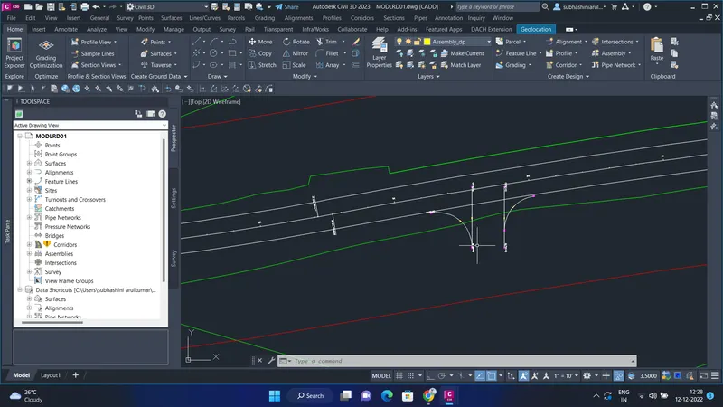
- we have to create a new alignment for that
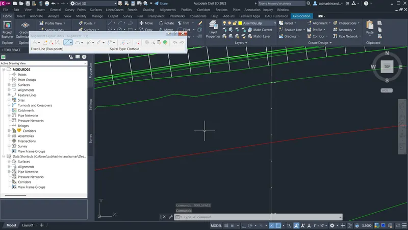
- first, we have to create a new alignment, click alignment select the alignment and draw it
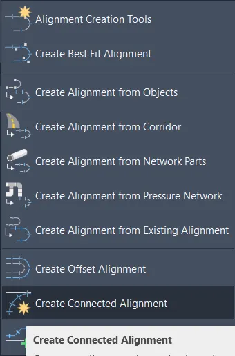
- next click on connect the alignment and select first alignment and second alignment and click ok
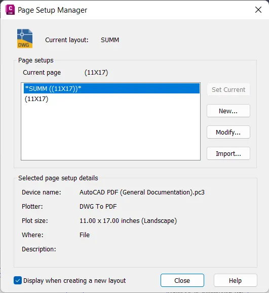
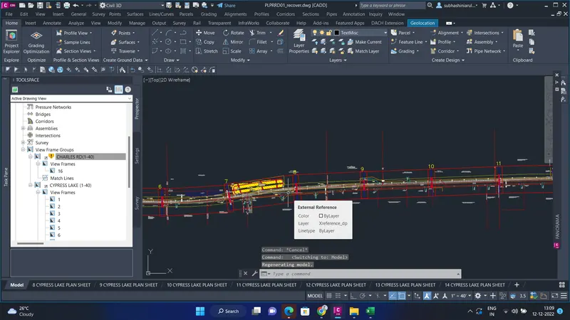
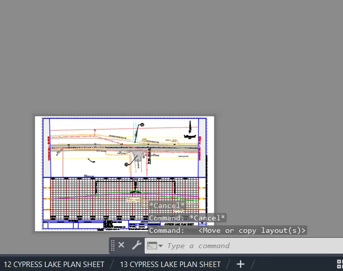
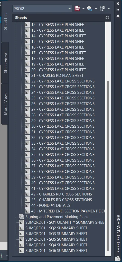
step: 13 creating a plan sheet and view frames
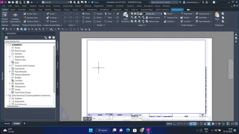
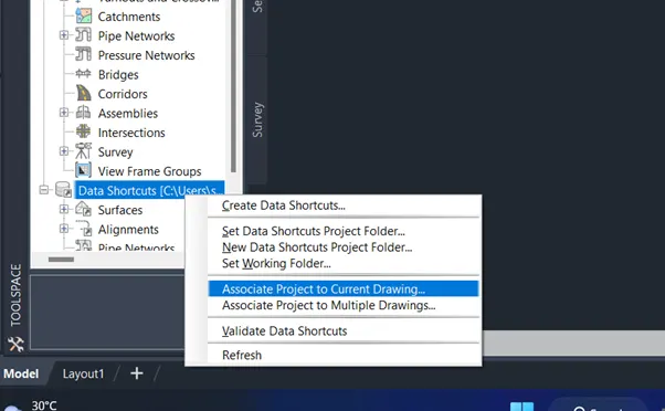
- open a new file with the company and template and create the data shortcuts for the file
- open the plan sheet in the civil 3d which is provided
step:14 creating estimation
dating all the excel sheets according to the given data 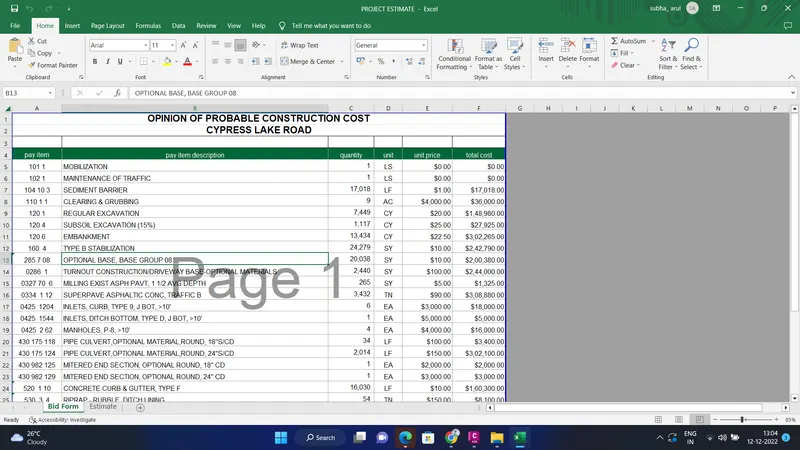
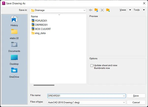
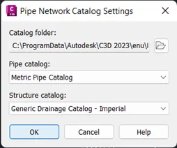
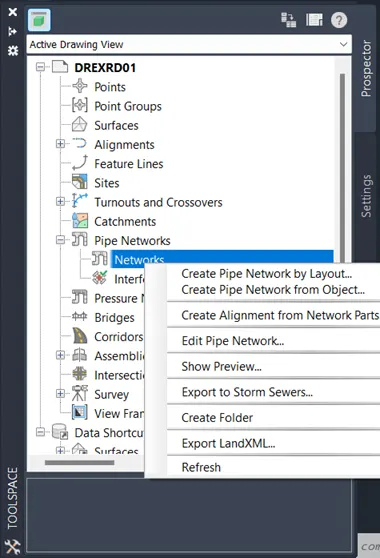
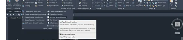
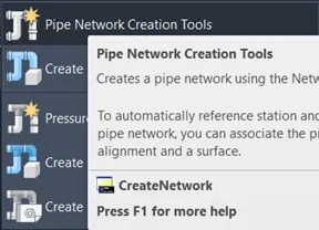
step :14 creating pipe networks
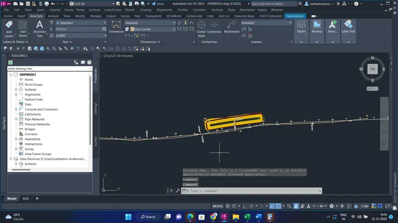
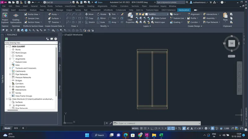
step: 15 creating box culvert