Project 2 - Lane National Highway Roadway Design in Civil 3D
Develop the road geometric design for a 2-lane NH concrete road with a paved shoulder for 80kmph design speed from the provided data.
1. Creation of surface.
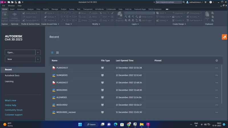
- click open civil 3d
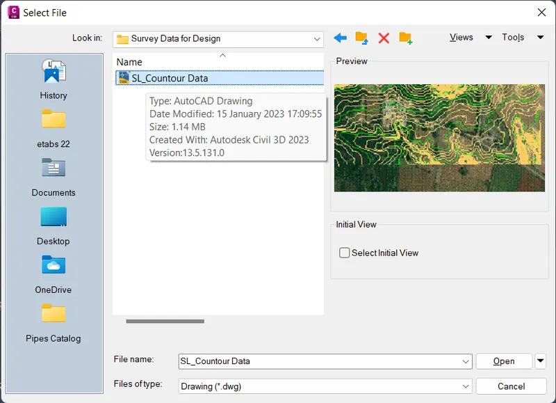
- open the SL-contour Data file
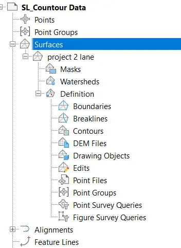
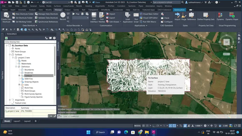
- Select contours from the prospector tab
- next, we have to surface for that click surfaces
- name the created surface ""
- Click Okay
2. Alignment & profile design.
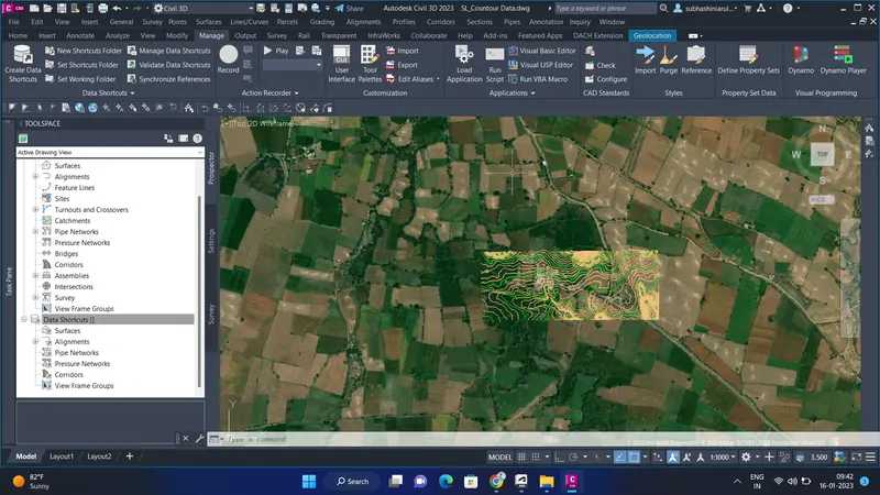
- after creating surface, type layoff in the comment box
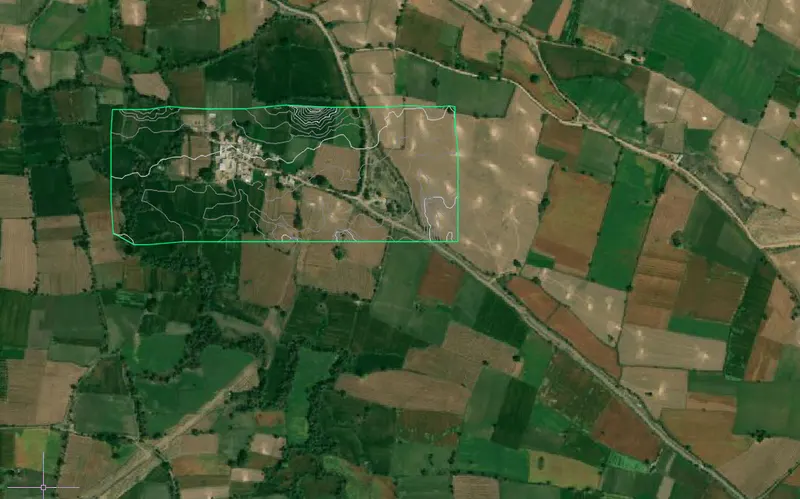
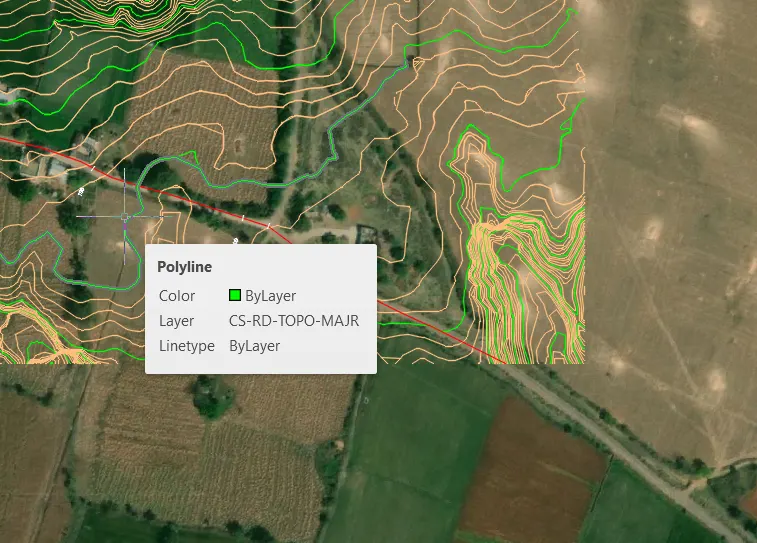
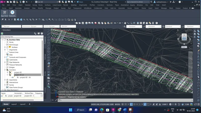
- the above image shows that created surface
- after creating the surface, the next step is to create the alignment
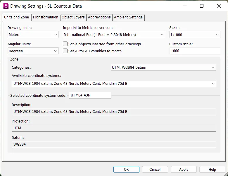
- for that we have to set a coordinate system.
- go to settings - edit drawing settings- enter the coordinate and click ok
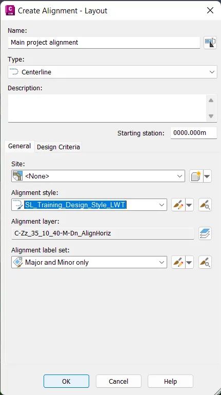
- next in the ribbon bar, click alignment and select create alignment by layout
- and select the alignment styles and necessary data for creating alignment.
- after clicking ok, the alignment tool will be opened
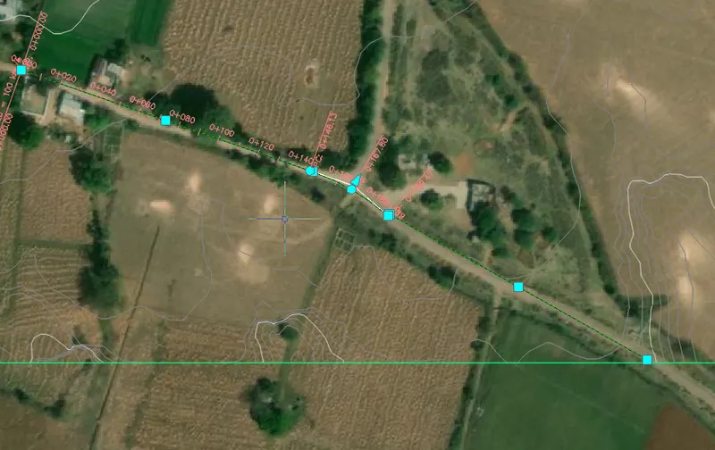
- next draw the alignment for the available surface
- and click ok alignment is created.
- in between if any curve is needed select accordingly and finish the alignment.
creating profile view:
go to profile
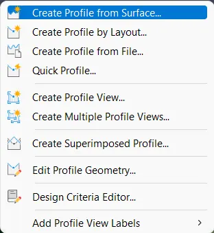
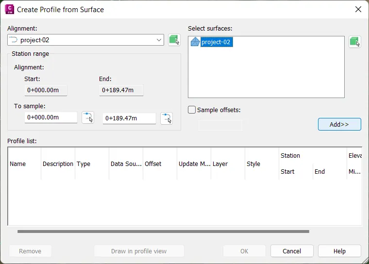
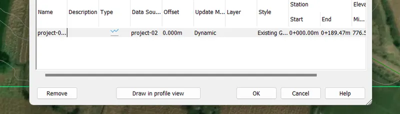
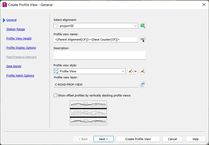
creating profile:
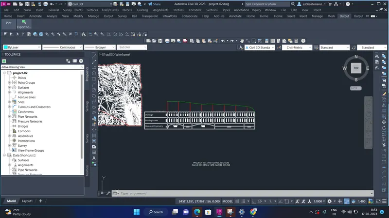
- Go to profile, select create a profile by layout
- and then create a profile-draw new toolbox will appear
- next give the name for the profile, profile label set, and profile style as per requirement and click ok
- In the profile layout toolbar
- Select fixed tangent(two points)
- click on Insert PVI and Select PVI to click on the profile and Esc, and select the free vertical curve(parabola)
- select the first entity & second entity as well as specify the curve length.

3. Creation of assembly & subassembly.
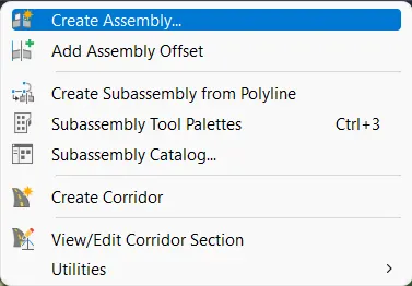
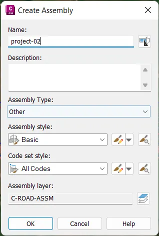
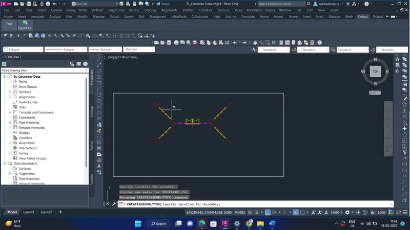
- next, we have to create an assembly
- go to the corridor, and select create assembly
- after clicking create an assembly, the assembly is created
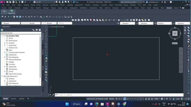
- next, we have to put a rectangle box outside the assembly.
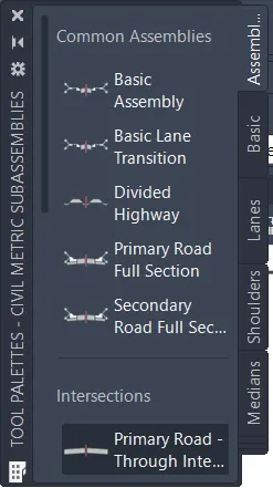
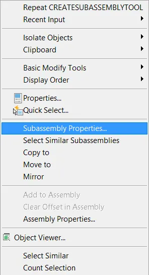
- after creating the assembly we have to create a subassembly.
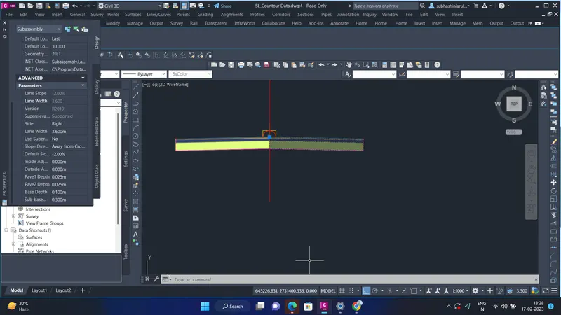
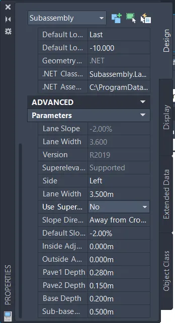
- after that click tool palettes, all the data are entered and click ok
- the assembly and subassembly are created.
4. corridor development.
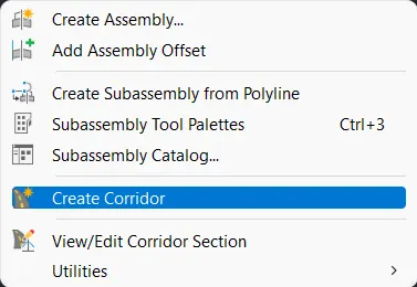
- next, we have to create a corridor for that go to the menu bar and click corridor
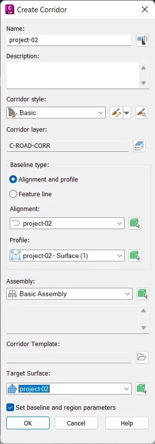
- click to create a corridor
- next the dialogue box open, and enter all the necessary data into the dialogue box
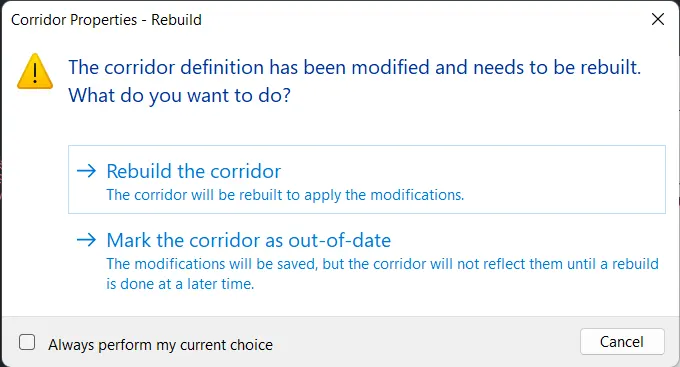
- and click ok, next in prospector right click corridor and select properties
- next dialogue box opens, click on information select object styles, next got to surface add surface for top link and bottom links and click ok
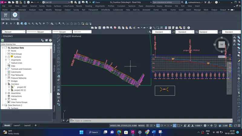
- acter finishing all the required data , click apply and close it
5. Section line & detail cross-section.
creating of section line
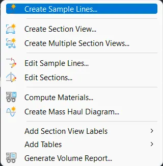
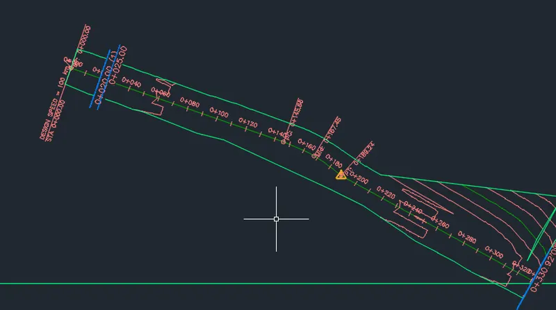
- click on the section on the menu bar, and next click on the create sample lines.
- the cursor opens, click on the alignment
- next, the dialog box opens, select the station
- net enter the value for the right swath length and left swath length
- next enter the baseline length and click ok
- the sample line is created

detailed cross-section:
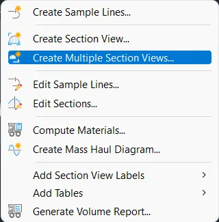
- next, we have to create a cross-section, for that click on the section
- the dialogue box opens and then select create multiple section views
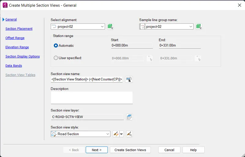
- after selecting create multiple section views.
- next, the dialogue box opens
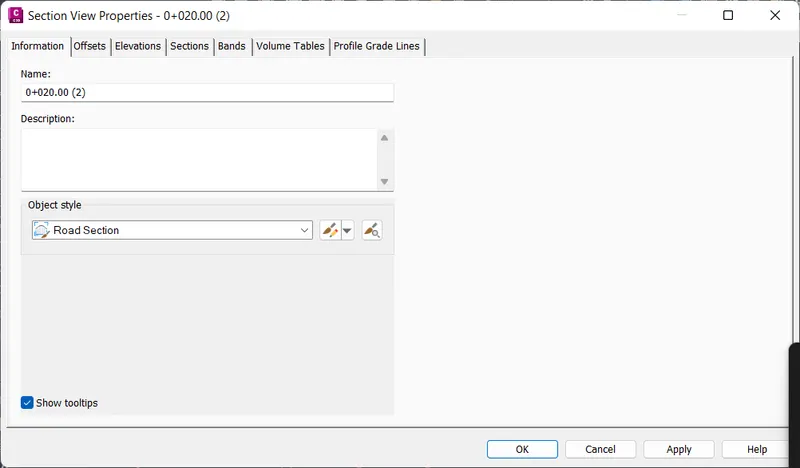
- next click on the cross-section and select section view properties
- the dialog box opens and types all the required data
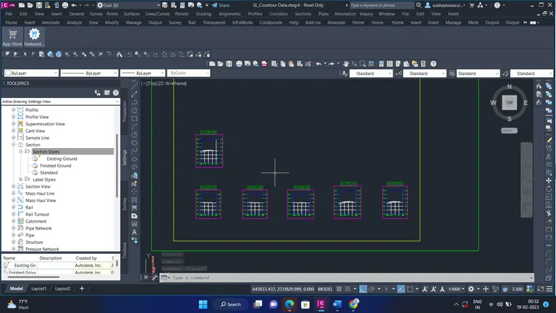
- now the detailed cross-section is created.