Project 1 - Geometric Design Parameter- Prerequisites
List all the highway elements required for Road Geometric Design as prerequisites & necessary checklists during design. eg. Design Speed, Design Vehicle etc.
ANSWER:
The geometric design of the highway:
Highway geometric design is concerned with all of the dimensions and layout of visual features of the highway to provide maximum efficiency, minimum cost, and reasonable safety.
The geometric design of a highway depends on several design factors.
- The following are the most important factors that control the geometric elements:
1. Topography
2. Design speed
3. Traffic factors
4. Design hourly volume and capacity
5. Environmental and other factors
1. TOPOGRAPHY OR TERRAIN
- The design speed is influenced by the topography or terrain conditions, which in turn governs the design of highway elements.
- The country's topography is classified as Plain, Rolling, Mountainous, or Steep based on its cross slope.

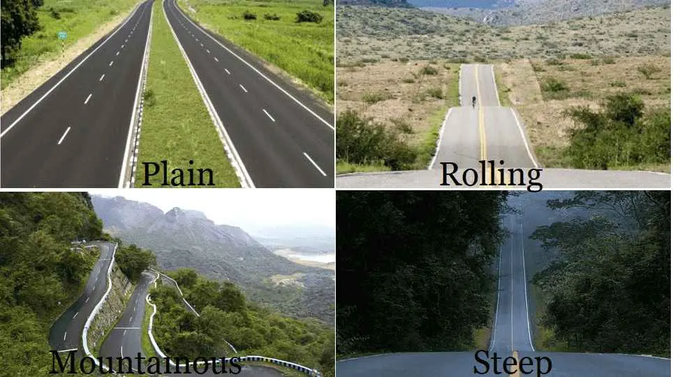
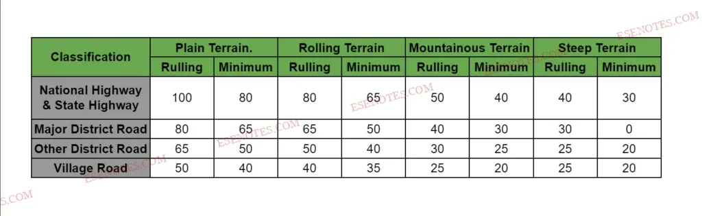
- For instance, in flat terrain, The maximum design speed on a state highway is 100 km/h, while the same speed on rolling terrain is limited to 80 km/h and 50 km/h on mountain terrain.
2. DESIGN SPEED
- The design of the vehicle's speed influences the following parameters: cross-section element, width, clearance, side distance, the radius of the curve, superelevation, transition, gradient, length of the submit curve, and so on.
- The design speed of a vehicle is determined by the type of topography or terrain classification and the road over which it travels. National Highway, State Highways, Major District Road, Other District Road, Village Road, and so on are examples.
- Since there are wide variations in the speed adopted by different drivers, and by different types of vehicles, design speed should be selected such that it satisfies nearly all drivers.
- At the same time, a higher design speed has a cascading effect on other geometric designs and thereby cost escalation. Therefore, an 85th-percentile design speed is normally adopted. This speed is defined as that speed which is greater than the speed of 85% of drivers. This is as high as 95 to 98 percentile speed in some countries.
3. Traffic factor
- Vehicle and human characteristics are examples of traffic factors.
- In the case of mixed traffic operations, the standard size of the vehicle (car) is considered when designing highway elements.
- Physical, mental, and psychological characteristics of the driver and pedestrian are examples of human characteristics.
4. DESIGN HOURLY VOLUME &CAPACITY
-
Because traffic volumes fluctuate over time, designing for peak hours is necessary, but it is highly inefficient.
-
As a result, "Design Hourly Volume" is used to design for a reasonable value of traffic volume.
5. ENVIRONMENTAL FACTOR
- The design of highway elements is also influenced by environmental factors such as aesthetics, air pollution, noise pollution, and landscaping.
Elements Of Highway Geometric Design:
The elements of highway geometric design include the following: cross-section elements, sight distance, horizontal alignment details, vertical alignment details, and intersection details.
- Cross-section element.
- Sight distance.
- Horizontal alignment details.
- Vertical alignment details.
- Intersection details.
1. cross section element:
These are the features of the pavement's cross-section that affect the pavement's life, riding comfort, and safety. The following are the pavement cross sections:
- Pavement surface characteristic
- Cross-Slope / Camber
- Width of Pavement or Carriageway
- Divider /Medians / Traffic separators
- Kerb
- Shoulder
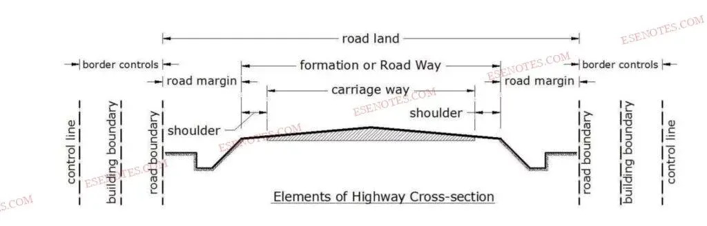
- Road Margin
- Roadway / Width of Formation
- Road Land / Right of Way
i.Pavement surface characteristic:
Pavement surface characteristics vary according to pavement type. This, in turn, is dependent on material availability, cost, traffic composition, climate conditions, and available construction methods. Pavement surface characteristics include the following:
- Skid and Slip
- Friction
- Unevenness Index
- Light Reflecting Characteristic
- Drainage
(i) Skid and Slip:
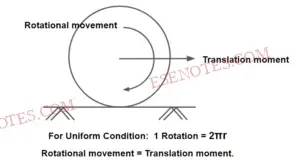
- Skidding occurs when the longitudinal moment of the wheel exceeds the rotational movement during the break (T.M>R.M). Friction resistance must be greater than braking force to avoid skidding.
- For Pure skid, Rotational movement =0, Translation moment ≠0.
-
Slipping occurs when the wheel revolves faster than the corresponding longitudinal movement along the road (R.M>T.M). It usually happens on slippery and wet pavement or when the road surface is slick with mud.
-
For pure slip, the rotational movement is zero and the translation moment is zero.
(ii) Friction:
- It determines the vehicle's operating speed and the minimum distance required to stop it.
- When the break is applied completely, maximum friction is created.
- Friction also governs the wheel's rotational transitional moment.
- It is further divided into two types:
a. Longitudinal frictions
b. Lateral or tranverse friction
a.longitudianl friction:
-
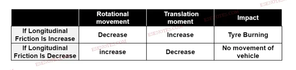
Longitudinal friction help support the movement of the vehicle.
-
Longitudinal friction depends upon speed, For high-speed friction is less.
b. Lateral or Traverses friction:
-
Lateral friction comes into the picture only when there is a lateral force on the vehicle.
Friction depends on the following factors:
-
Type of pavement surface (CC, Bitumen, Earthen material, WBM).
-
The roughness of the pavement (Texture).
-
Condition of pavement (Dry, Wet, Rough Smooth).
-
Condition of tyres ( New with good threads or old with worm-out threads).
-
Speed of vehicle.
-
The extent of brake application ( Full or Partial).
-
Load and tyre pressure.
-
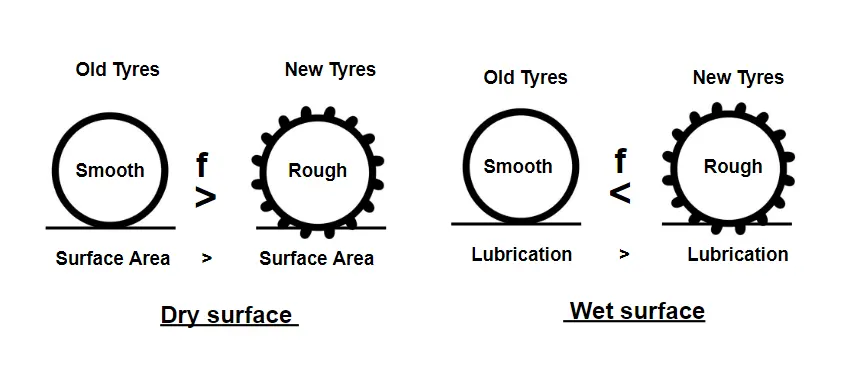
The temperature of tyre and pavement: On the Dry Surface coefficient of friction of the old tyre is greater than the new tyre. And on the wet surface coefficient of friction of the old tyre is lesser than the new tyre.
(iii) Unevenness Index:
- The presence of undulations on the Pavement surface is called Unevenness.
- The Unevenness index is defined as cumulative undulation per kilometre of road length.
- It is expressed in terms of mm/Km.
- It is measured by BUMP INTEGRATOR. (Developed by CRRI)
- Uneven surface increases riding discomfort, fuel consumption, wear and tear of tyres and other parts and accidents.
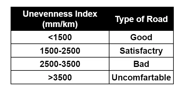
The different values of the Unevenness Index and the corresponding serviceability of the road are as follows:
Note- Internationally Roughness is measured in terms of IRC ( IRC=INTERNATIONAL ROUGHNESS INDEX).
𝐵𝐼=630(𝐼𝑅𝐼)1.12
BI = BUMP INTEGRATOR (mm/km)
IRC=INTERNATIONAL ROUGHNESS INDEX (m/km)
An unevenness of the pavement depends upon the following factors.
-
Improper Compaction.
-
Use of improper construction method.
-
Use of inferior quality material.
-
Improper surface and sub-surface drainage.
-
Poor maintenance of pavement surface
(iv) Light Reflecting Characteristic:
- Visibility over the pavement surfaces depends upon their colour and light characteristics.
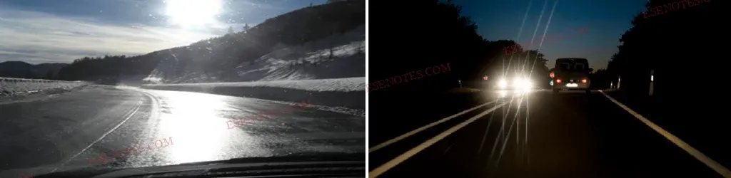
- The glare cases by the reflection of the headlight are high on wet pavement surfaces than on dry pavement.
- Light-coloured pavement surfaces give good visibility at night but produce more glare during the daylight while on the other hand black pavement has poor visibility at night.
(v) Drainage:
- The pavement must be completely impermeable so that water does not seep into the pavement layers, and the geometrical pavement surface should be such that it aids in the removal of water from the surface quickly.
Camber / Cross-Slope:
It is the transverse slope provided to the road surface to drain rainwater from the road surface to avoid the following:
- In the presence of water, bitumen is stripped from aggregate.
- To prevent swelling of the subgrade if water seeps up to it.
- The vehicle slipped on the wet pavement.
- Glare from a wet pavement surface.
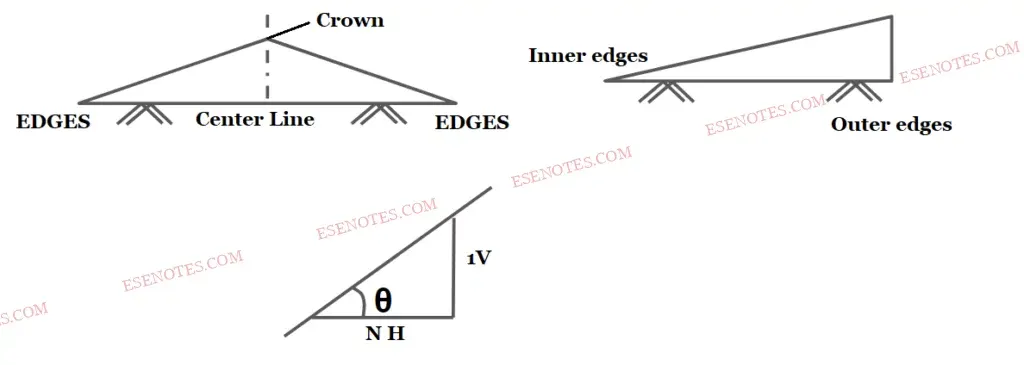
On a straight road, it is provided by raising the carriage way's centre concerning the edges, forming a crown at the highest point along the centre line.
Surface drainage is provided by raising the outer edge of a horizontal curve with superelevation.
- It is represented in any of the following ways:
- A percentage: For example cross-section 5% ⇒ tanθ = 5100.
- As fraction: For example cross-section = 1 in 20 = 120 = 0.05.
- The value of the cross-section depends on the following factor:
- Type a pavement surface
- Amount of rainfall
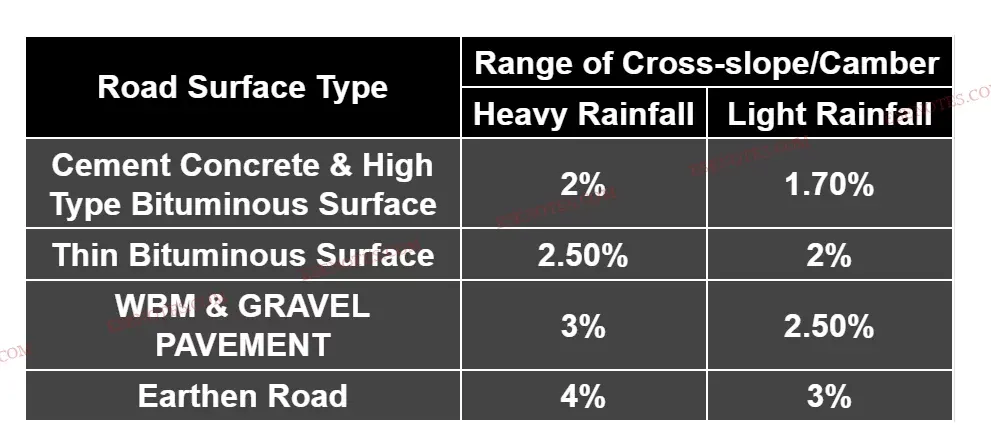
Type of Cross-Slope / Camber
1. Straight line Cαmber
2. Parabolic Cαmber
3. Composite Cαmber
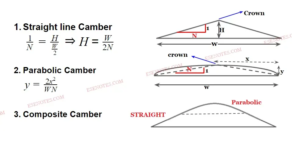
Note: For cement concrete pavement straight-line camber is preferred. As it is easier to lay.
Gradient = 2x Cαmber
width of pavement or carriageway
- It is the transverse slope provided to the road surface to drain rainwater from the road surface to avoid the following:
- In the presence of water, bitumen is stripped from aggregate.
- To prevent swelling of the subgrade if water seeps up to it.
- The vehicle slipped on the wet pavement.
- Glare from a wet pavement surface.
- On a straight road, it is provided by raising the carriage way's centre concerning the edges, forming a crown at the highest point along the centre line.
Surface drainage is provided by raising the outer edge of a horizontal curve with superelevation.
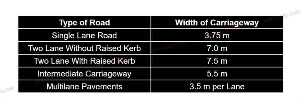
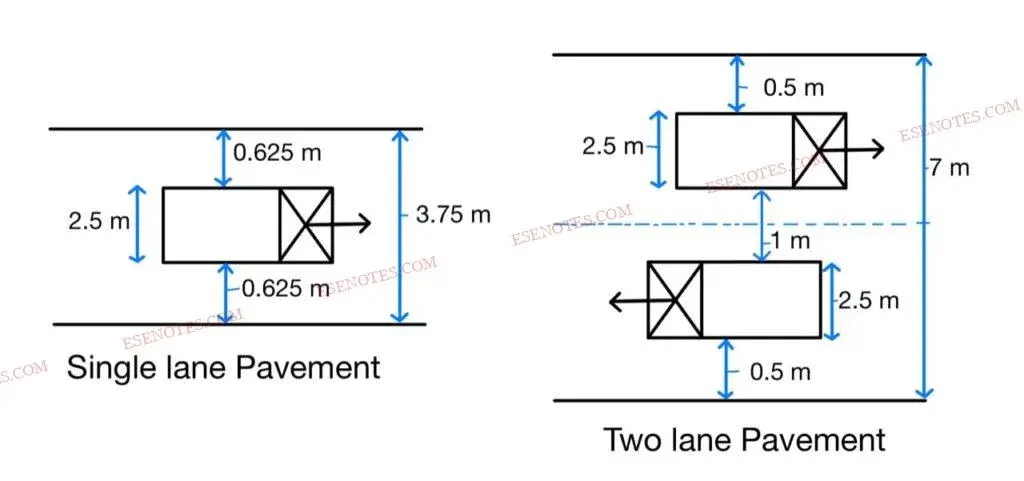
Divider/median/traffic separate
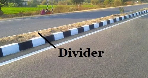
- The divider is an element provided to Road along the centre line to separate two-way traffic. The main function of the median is to prevent “Head Collision” between vehicles moving in the opposite direction. it also serves the following other parts:
- To channel traffic into the streams.
- To protect the pedestrians.
- The glaring effect due to the Headlight of the opposite direction vehicle can be reduced.
- To segregate the slow traffic.
- Medians can be provided in the following forms:
- As pavement marking
- Physical dividers (Mechanical separator)
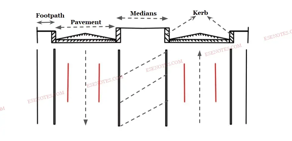
- The desirable width of the median is 8- 14 meters. ( It includes the provision for future expansion of roads)
- To reduce the glare of the headlight of opposite moving vehicles minimum width required is 6 meters.
- IRC recommended minimum width of 5 meters for the divider that can be reduced to 3 meters where land is restricted.
- The bridge width required for the median is in the range of 1.2 to 1.5 meters.
- In urban areas, the minimum width of the median to be provided is 1.2 meters & desirable min is 1.5 meters.
- For the Expressway min width to be provided is 12 meters and the desired is 15.5 meters.
kerb
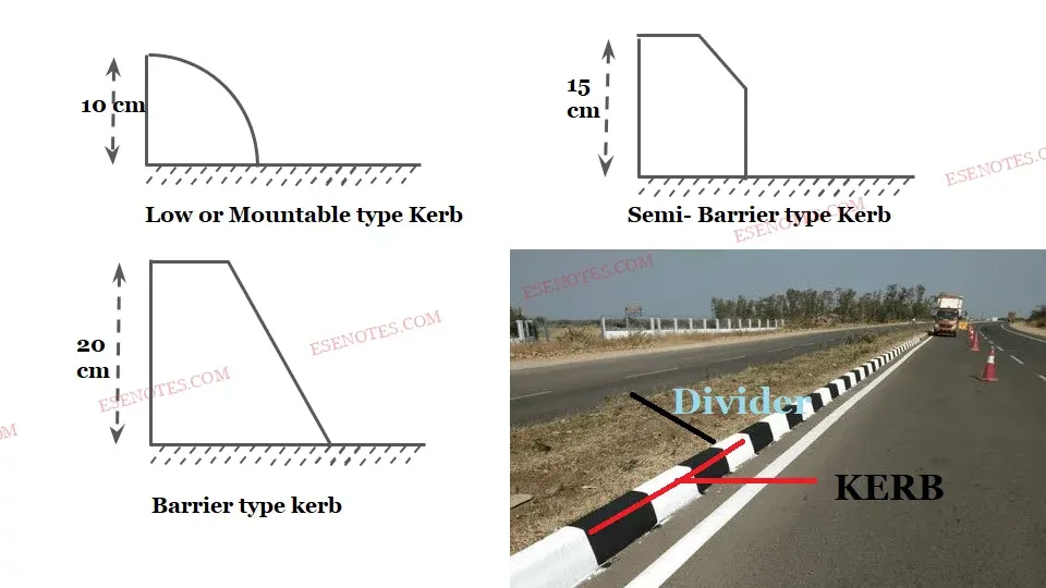
- Low or Mountable type Kerb
- Semi- Barrier type Kerb
- Barrier type kerb
- Kerb is a separator between pavement & footpath. It provided lateral support to the pavement.
- Kerb is mainly divided into the following 3-categories.
1. Low or Mountable type Kerb:
- The height of this type of kerb is about 10 cm with a slope or batter to help the vehicle climb the kerb easily.
2. Semi-Barrier type Kerb:
- The height of this type of Kerb is about 15 cm with a batter of 1:1 on the top 7.5 cm. It is provided where pedestrian traffic is high. ( Pedestrian = A person who is walking in the street.)
3. Barrier type kerb:
- The height of the kerb stone is about 20 cm with a batter of 1:4.
Kerbs serve two purposes:
- they facilitate and control drainage.
- To mark the pavement edge.
- To give a more polished appearance.
- To reinforce and manufacture the pavement edge.
SHOULDER:
Shoulder refers to the extra width provided adjacent to the pavement's edge. It is provided for emergencies such as vehicle breakdowns, medical emergencies, and so on.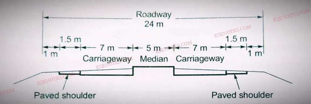
- The minimum width of a highway shoulder is 2.5 metres.
- The cross slope of the shoulder should be 0.5% greater than the cross slope of the adjoining pavement, with a minimum value of 3% and a maximum value of 5%.
- 5% cross slope (shoulder) equals (0.5%+ cs of pavement) 3%
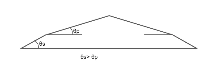
Slope of Shoulder
ROAD MARGINS:
These are the areas that do not have regular roadways. The following elements are included in the road margins:
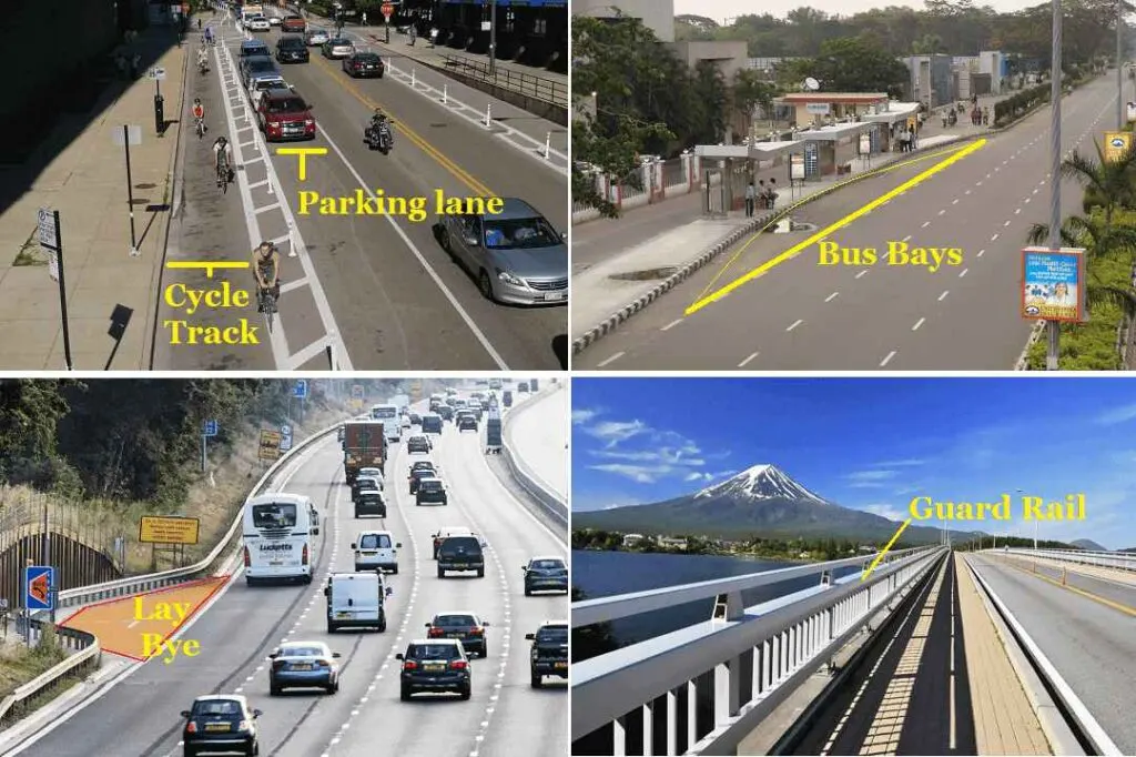
1. Parking lanes: These are usually provided on city streets to allow for car parking. Parallel parking is usually provided for safe vehicle movement. However, angle parking is also available. The parking lane should be wide enough. Parallel parking requires a width of 3.0 m.
2. Lay-banes: are provided near public conveniences to avoid conflict with running traffic. The minimum width is 3 metres.
3. Cycle tracks: these are provided in urban areas to ensure the safe movement of cyclists. The minimum width required for the cycle track is 2 metres, which can be increased by 1 metre for each additional cycle lane.
4. Driveways: These are used to connect the highway to commercial establishments such as gas stations, service stations, and so on.
5. Guard rails: these are installed at the edge of the shoulder when the road conditions are deteriorating to prevent vehicles from running off the slope. Guard stones are put at an appropriate distance to improve night visibility on curves under car headlights.
6. Service roads: these run adjacent to the roadway and are separated by a separator, with access to highways available only at certain spots. They are supplied to alleviate motorway and motorway congestion.
7. Bus Stops: They must be provided at least 75m away from the intersection and may be provided by recessing the kerb to avoid collision with moving traffic. It is used for the secure transportation of passengers and cargo from buses.
ROADWAY/ WIDTH FORMATION:
It is the total of the pavement or carriageway, including any separators and the shoulder.
The width of a highway is measured from the top of the embankment to the bottom of the cutting, excluding the side drain.
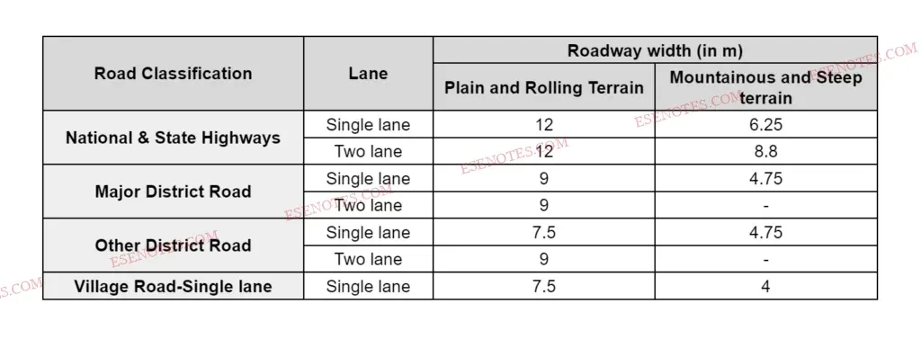
The width of the formation of various road classes is as follows:
RIGHT OF WAY/ROAD LAND:
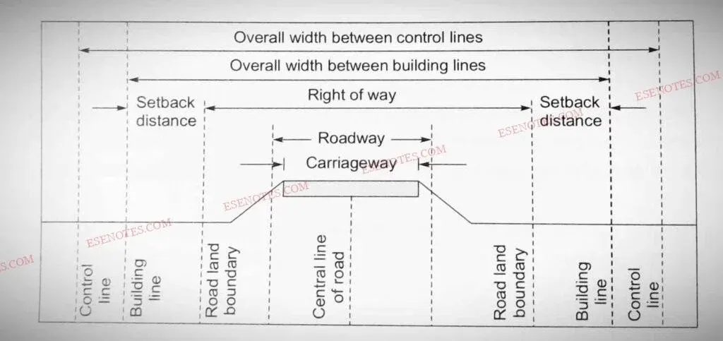
- It is the area of land acquired for the road along its alignment, with future extension in mind.
- Construction of a specific type of building is only permitted if a suitable setback from
- the road border up to the Central line is provided.
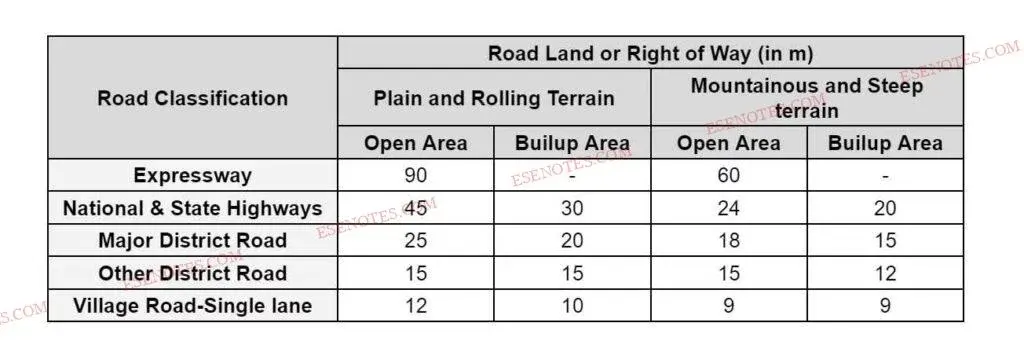
- Land width for different roads in rural locations, or as follows:
Right of Way
- Sight Distance:
- Sight distance on a highway depends upon the following factors:
- Sight distance are of following types:
SIGHT DISTANCE:
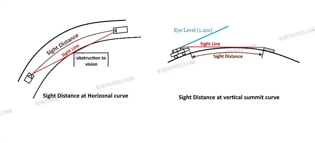
The length of the road visible to the driver at any distance is referred to as sight distance. (It is calculated by assuming the driver's eyes are 1.2 m tall and the object is 0.15 m tall).
SIGHT DISTANCE ON CURVE
Restriction to the visibility/sight distance may be caused in the following cases:
- At a horizontal curve, when the line of sight is obstructed by the object and the inner side of the curve.
- At a vertical curve the line of sight age of obstructed by the road surface of the curve.
- At an uncontrolled intersection when a driver from one of the approach roads is able to sight a vehicle from another approach road towards it at the intersection, due to the presence of obstruction.
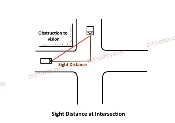
The sight distance available to the driver depends upon the following factors:
- Horizontal curve, vertical profile, traffic condition, and position of obstruction on the road ahead.
- Driver's eye level above the road surface.
- The object's height is above the road surface.
Sight distance on a highway depends upon the following factors:
- Total Reaction Time of Driver
- Design speed
- Braking Efficiency
- Frictional Resistance Between Road and Tyres
- Gradient of Road
1. TOTAL REACTION TIME OF DRIVER:
It is the time elapsed between the moment the object becomes visible to the driver and the moment the brakes are applied effectively.
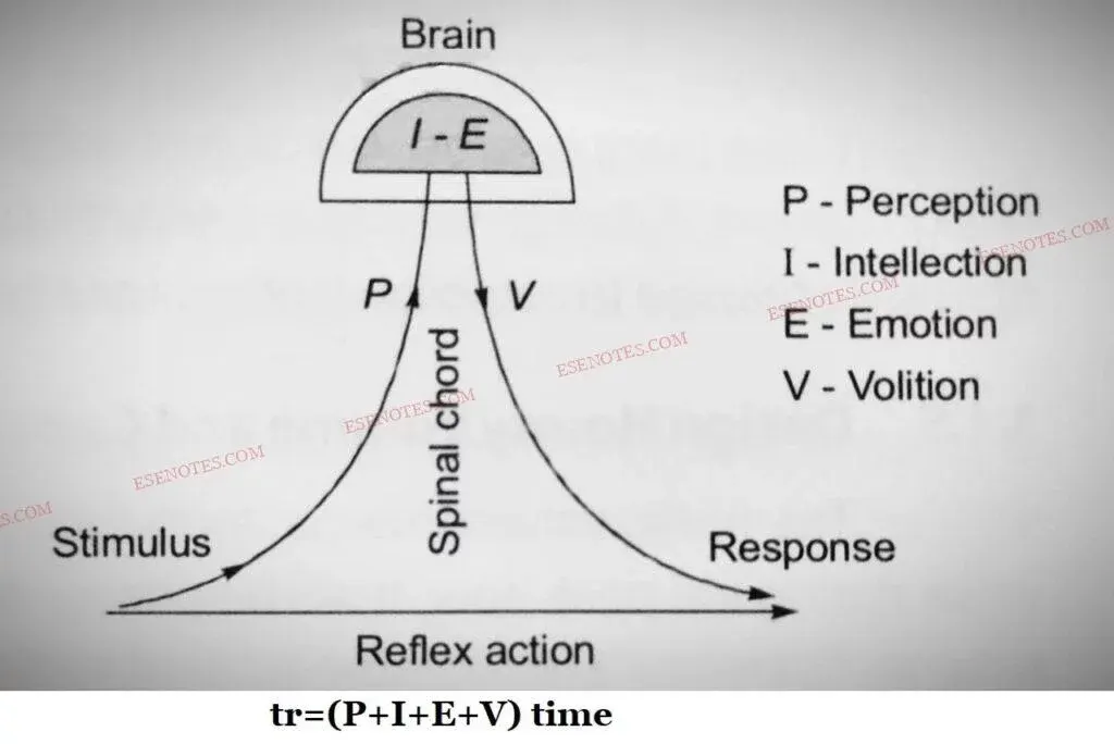
The entire reaction time is further subdivided into various components, which can be explained as follows:
i.Perception (P): The time it takes for a driver's eyes or hearing to communicate a sensation to the brain via the neurological system and spinal cord.
ii. Intellection Time (I): the amount of time it takes the driver to comprehend the scenario. It is also the time required for comparing various ideas, regrouping, and recording new sensations.
iii. Emotion Time (E): The time elapsed between the onset of emotional sensations and other mental disturbances such as fear, wrath, superstition, and so on, and the onset of the circumstance. This time varies from person to person and even from scenario to situation.
iv. Volition Time (V): The time it takes a driver to complete a final action, such as applying the brakes.
The preceding is known as a "PIEV" analysis for Total Reactions Time.
2. design speed:
- During the total reaction time of the driver, the distance moved by the vehicle depends upon the design speed.
- If the speed of the vehicle is not mentioned in the problem then consider the design speed of the highway as the speed of the vehicle.
- Braking distance means the distance travelled by vehicle before coming to a stop/half also depends on design speed.
3. Braking Efficiency:
- The efficiency of brakes depends upon the age and characteristics of the vehicle. If we say the brakes are 100% efficient, it means the vehicle will stop at the moment of application of brakes. But practically 100% efficiency update is not achieved, otherwise skidding will occur which is uncontrollable and dangerous for the vehicle and road users.
- For the design purpose of the highway, we considered the 50% brake efficiency of the vehicle.
4.Frictional Resistance Between Road and Tyres:
- The frictional resistance developed between the road and tyres depends on the coefficient of friction.
- Higher is coefficient of friction, higher is the frictional resistance and lower is SSD.
- Coefficient of friction further depends upon the condition of tyres and Road.
- It is further linked with the design speed of vehicle as follows:

5.Gradient of Road (If Any):
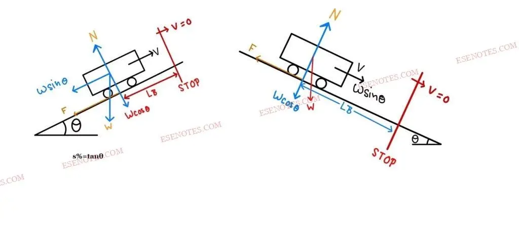
- When we are going down on a gradient, gravitational force also come into action which causes the vehicle to take more time to stop the vehicle means more sight distance is required. While in climbing up a gradient less sight distance is required because the time taken to stop the vehicle will be less.
Sight distances are of the following types:
- Stopping sight distance (SSD).
- Safe overtaking distance (OSD).
- Intermediate sight distance (ISD)
- Safe sight distance for entering into the uncontrolled intersection.
- Headlight sight distance.
Stopping Sight Distance (SSD):
The minimum distance visible to a driver ahead to safely stop a vehicle travelling at design speed without collision with any other obstruction is termed as “SSD”. It is also termed as “Absolute Minimum Sight Distance” or ” Non-Passing Sight Passing”.
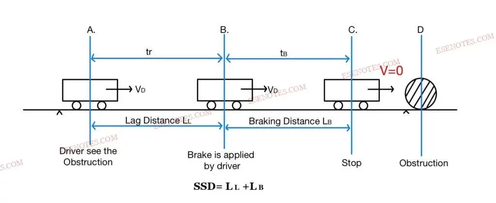
The stopping distance of the vehicle includes:
- Lag Distance (𝐿𝐿)
- Braking Distance(𝐿𝐵)
(I). Lag Distance (𝐿𝐿)
- The distance travelled by a vehicle at uniform design speed during the total reaction time (tr) termed as “Lag Distance (𝐿𝐿).
|
𝐿𝐿=𝑉×𝑡𝑟 . |
𝑉= Design Speed(m/sec). |
As per IRC reaction time is taken to be 2.5 seconds for SSD.
(II). Braking Distance(𝐿𝐵)
- The distance travelled by the vehicle after the application of the brake, is termed Braking Distance(𝐿𝐵).
Note:
- SSD must be available at all times on the road.
- Because the SSD required on descending gradients is greater, it is vital to calculate the critical value of SSD for descending gradients on graded roads and for two-way traffic flow.
- On narrow roads or single-lane roads with two-way traffic, the minimum SSD is twice
- he SSD required to allow both vehicles arriving from opposite sides to stop.
(For a one-lane road with two-way traffic)
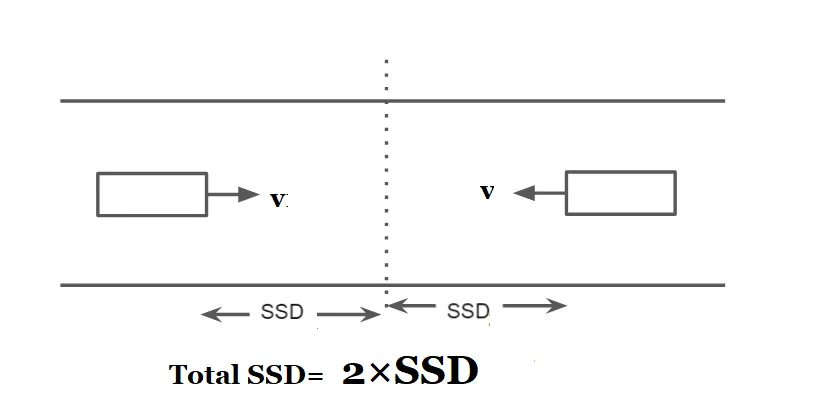
- If SSD cannot be supplied on any stretch of road due to an unavoidable cause for the design speed available, the speed should be limited either by erecting speed-limit restriction signs or by forcing the speed to be reduced.
- This is just temporary, and efforts must be made to offer SSD over time. (By modifying the road's alignment or removing the obstruction.)
- IRC recommends the following SSDs:

Overtaking Sight Distance (OSD):
- If all vehicles ply on the road at the design speed, there would theoretically be no need for overtaking, but this rarely occurs, thus the vehicle travelling at the design speed must overtake the slow moving vehicle.
- OSD, or "Safe Passing Sight Distance," is the minimal distance open to the driver's view when attempting to overtake a slow moving vehicle while remaining safe from traffic in the opposite direction.
- OSD is measured along the centre line of the road, with the driver's eye level at 1.2 m above the surface and the object at 1.2 m above the surface.
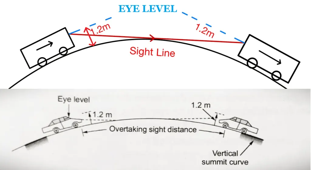
OSD Influencing Factors:
- Vehicle speed, Overtaking vehicle, Overtaken vehicle, Vehicle arriving from the opposite way.
- Driver reaction time and skill.
- Road gradient.
- The overtaken vehicle's condition determines the rate of acceleration.
- The distance between two vehicles.
Analysis of OSD:
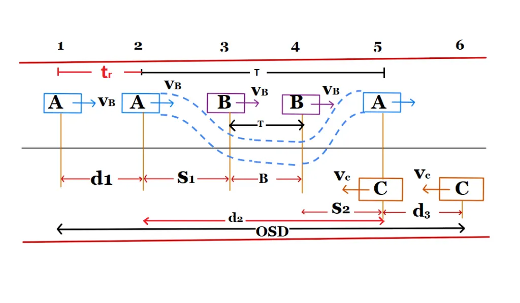
The overtaking manoeuvre could be divided into three operations, as follows:
- d1:- It is the distance travelled by overtaking vehicle "A" during the driver's response
- time "tr" before beginning to overtake vehicle B at VB speed.
- d2:- the distance travelled by vehicle "A" during the actual overtaking operation at time "T".
- d3:- It is the distance travelled by an approaching vehicle "C" during the actual overtaking action of a for time"T".
Assumption in OSD analysis:
- For reaction time, the overtaking vehicle is compelled to slow down to the speed of the overtaken vehicle.
- When the driver of vehicle "A" finds a sufficient clear gap, he or she must determine whether or not to overtake within a reaction time.
- During the time "T," the vehicle "A" accelerates and overtakes the vehicle "B" by a distance d2.
- The distance d2 is broken down into components.
- During this overtaking time "T," the vehicle "C" travelling in the opposite direction travels d3 distance.
case.1
|
d1= vb·tr (m) |
vb (m/sec)= speed of the slow moving vehicle, tr = Reaction Time (2 sec). |
|
d1= 0.278vb·tr (m) |
vb (km/hr) |
As per IRC reaction time is taken to be 2.0 second for OSD.
case.2
d2= s1+s2+B.
s1 or s2= minimum spacing between the two vehicle, which depends upon their speed. It is also termed as space headway. but for design s1=s2=s (s1+s2= 2s).
d2= 2s +B.
Space Headways
|
s = (0.7×vb +6) m. |
vB put in metre/second. |
|
s= (0.7×0.278×vb +6) m. |
|
|
s= (0.2×vb +6) m. |
vB put in kilometre/hours. |
B= Distance traveled by vehicle ‘B’ of speed vb and time ‘T’.
|
B= vb·T (metre) |
vB put in metre/second. |
|
B= 0.278×vb×T (metre) |
vB put in metre/second. |
Here
|
d2= vbT+ 12×a·T² |
[d= ut+ 12at²]
a= acceleration of overtaking vehicle (m2/sec) |
|
2s+ B= vbT+ 12×a·T² |
|
|
2s+ |
|
|
T= √4s/a |
|
d3 = vc ·T (m) |
vc =design speed of road (km/hr). |
|
d3 = 0.278vc ·T (m) |
vc =design speed of road (m/sec). |
OSD= d1 + d2 + d3 metres.
|
OSD= vb·tr + vbT+ 2s+ vcT metres. |
|
| vb and vc in m/s, tr and T in sec | |
| OSD= 0.278vbtr +0.278vbT+ 2s+ 0.278vcT metres. | |
| vb and vc in km/h, tr and T in sec | |
NOTE:
- If vb value is not given, then assume:
|
vb = vc– 4.5m/sec |
vb & vc in m/sec. |
|
vb = vc– 16kmph |
vb & vc in kmph. |
vc =design speed of road.
- On divided Highways with one way traffic the overtaking distance need to be only (d1 + d2) because no one expected from the opposite direction.(On divided highways, d3 need not be considered)
- On divided highways with four or more lanes, IRC suggests that it is not necessary to provide the OSD, but only SSD is sufficient.
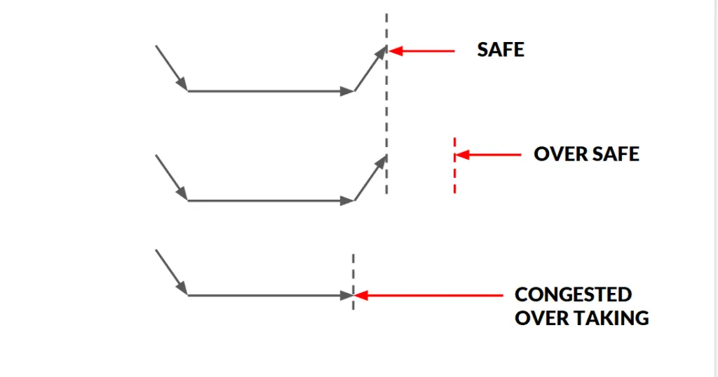
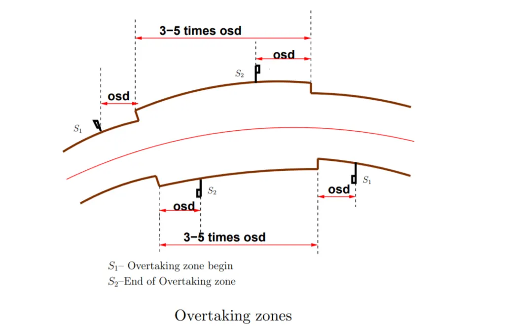
overtaking zone:
- When OSD cannot be given over the entire length of the route, overtaking zones are provided.
- These are designated overtaking zones, denoted by broad highways. Overtaking zones should be 5 times OSD in length, with a minimum of 3 times OSD.
Intermediate sight distance (ISD):
- On a horizontal curve, the requirement of overtaking sight distance can not always be satisfied. In such cases overtaking is prohibited by using regulatory signs. To provide an opportunity for overtaking operation on horizontal curves or in restricted areas, we provide intermediate sight distance, i.e. equals to twice of stopping sight distance.
ISD= 2×SSD
- The measurement of the ISD may be made assuming both the height of eye of driver & height of object to be 1.2m.
Intersection sight distance
- At intersections where two or more roads connect, a clear view across the corners from a reasonable distance should be provided to avoid car collisions.
- The viewing distance should be set such that drivers on both sides can see each other.
- The sight triangle is the area of unimpeded sight formed by the lines of vision, as depicted in Design of sight distance at intersections may be used on three possible conditions:
• Enabling approaching vehicle to change the speed
• Enabling approaching vehicle to stop
• Enabling stopped vehicle to cross a main road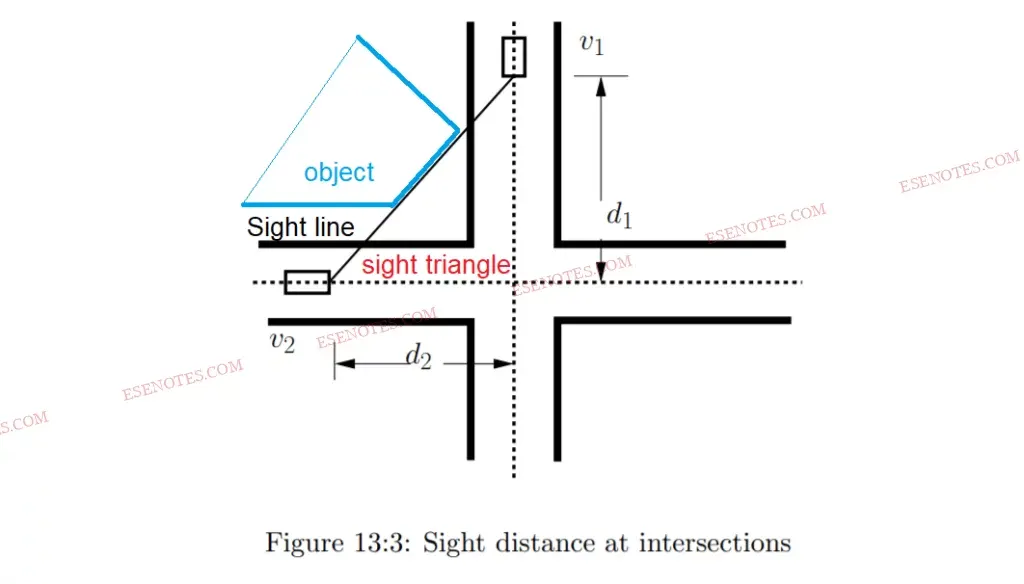
curves:
-
Curves are used on highways to ensure that the change in direction at the intersection of straight alignments, either in the horizontal or vertical plane, is gradual.
-
Curves are required for a variety of purposes, including:
* The country's topography
* to allow access to a specific location
* Property-imposed constraints
* Existing amenities should be preserved.
* Avoiding existing religious, monumental, and other expensive structures
* Utilizing existing rights of way
Factor Affecting the Design of Curves
The various factors which affect the design of curves are:
- Design speed of the vehicle
- Maximum permissible superelevation
- Allowable friction
- Permissible centrifugal ratio
Type of Curves
Curves have been divided into two classes:
(1) Horizontal Curve: A curve in plan to provide change in direction of the central line of a road.
(ii) Vertical Curve: A curve in the longitudinal section of a roadway to provide for easy change of gradient.
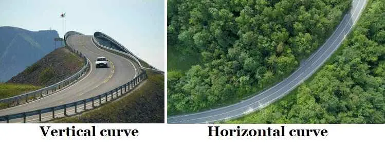
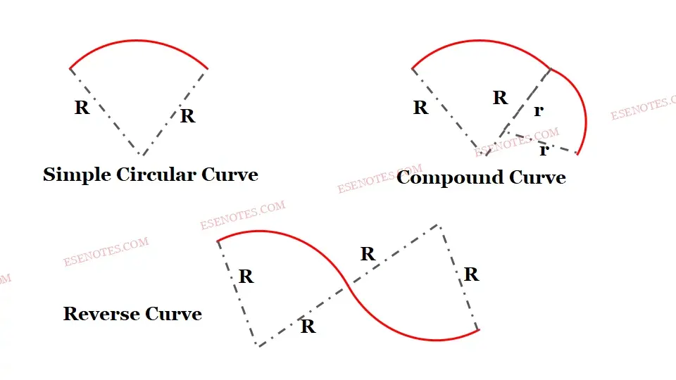
The different types of curves used in highways are:
(i) Simple Circular Curve: A simple cùrve consists of a single are connecting two straights.
(ii) Compound Curve: A compound cùrve consists of a series of two or more simple curves that turn in the same direction and join at common tangent points.
(iii) Reverse Curve: A reverse cúrve consists of two simple curves of opposite direction that join at the common tangent point called the point of reverse curve.
Various design element to be considered in the horizontal alignment are:
- Design speed
- Type and length of transition curve
- Width of pavement
- Super elevation
- Radius of circular curve
- Set back distance
Design Speed:
- The design speed is main factor on which most of the geometric design element depends including horizontal elements.
- The design is speed of road depends, upon class of road and terrain.
- Classification of terrain & design speed for different class of road is as follows:
- Design speeds are also being defined for urban roads.
- Two values of speed is ruling and minimum are being specified for each type of Road.
- As far as possible, attempt most to be made to design all the geometric element for ruling speed however it site conditions and economic consideration does not permit so, design must be done for minimum design speed.
superelevation:
Superelevation is the transverse inclination along the length of a horizontal curve caused by lifting the outer edge in relation to the inner edge in order to offset the influence of centrifugal force (or cant or banking).
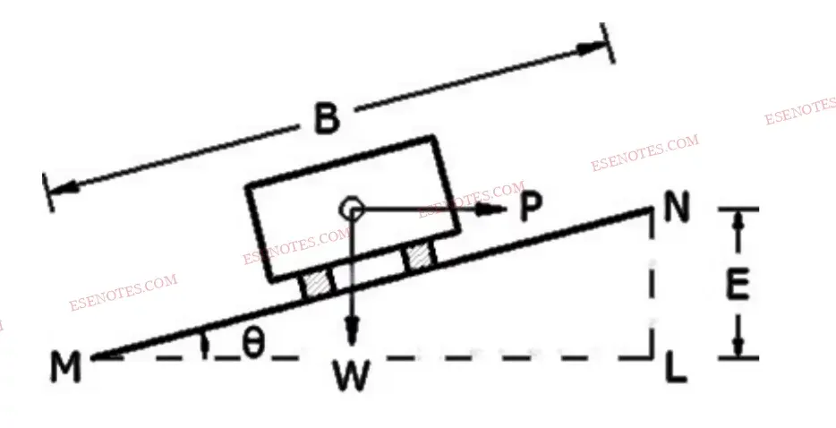
The superelevation ‘e’ is expressed as the ratio of height of outer edge w.r.t. the horizontal width, i.e
Superelevation (e)= 𝑁𝐿𝑀𝐿
e= tanθ
θ is very small and the value of tanθ ⊁ 0.007 (7%)
e= tanθ ≅ sinθ = 𝐸𝐵
Formula for Superelevation
e+f=𝑉2/127𝑅 , V in km/h
Equilibrium Superelevation:
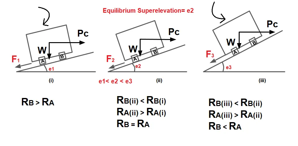
Equilibrium superelevation is that superelevation at which pressure at the inner and outer tyre will be equal. if the coefficient of friction is neglected i.e. f =0 then,
e=𝑉2/127𝑅 , V in km/h
Superelevation As Per IRC
1.Maximum Superelevation
| Type of Road | Maximum Superelevation (emax) |
| Urban Road | 4% or 0.04 |
| Plain & Rolling Terrain | 7% or 0.07 |
| Mountainous & Steep Terrain | 10% or 0.10 |
2.The minimum superelevation
It is provided on a road must not be less than the camber of the road for the adequate drainage of water from the surface.
Method of Obtaining Superelevation:
- Superelevation on a horizontal curve in the field is a crucial characteristic in building.
- The maximum super-elevation is reached at the conclusion of the transition curve or at the start of the circular curve.
- The achievement of superelevation can be divided into two parts:
- Removal of the cambered section's crown
- Pavement rotation to achieve full superelevation
i) Elimination of crown of the cambered section
This may be done by two methods:

ii) Rotation of pavement to attain full super-elevation
When the crown of the camber is eliminated, It does not signify that superelevation desired at that section is attained.If desired superelevation is more than camber/ cross sections for the payment section will have to be rotated for the till the desired superelevation is attained.
Desire superelevation can be attained by two method:

Method 1
By rotating the pavement cross section about the centre line, depressing the inner edge & raising the outer edge each by half the total amount of superelevation required with respect to centre.
Method 2
By rotating the pavement cross section about the inner edge of the pavement raising both centre as well as the outer edge of the pavement such as the outer edge is raised by the full amount of superelevation desired.
| Rotation about center line | Rotation about inner edge |
| It may with interfere drainage system. | No interference with drainage system. |
| Centre line remain unchanged. | Centre line is elevated. |
| Earth work is balanced in cutting & filling. | Filling is required. |
In cases where a transition curve cannot be provided for some reason, 2/3 of superelevation may be attained at the straight portion before the start of the circular curve and the balance 1/3 is provided at the beginning of the circular curve.
The superelevation is introduced by raising the outer edge of pavement at a rate not exceeding (1 in 150) in plain & rolling terrain and (1in 60) mountainous & steep terrain.
Radius of Horizontal Curve
Horizontal curve of highways are designed for the specified design speed (Ruling & Min).
However if this is not possible due to site restriction, the horizontal curve may be redesigned.
On the basic of speed Radius of Horizontal Curve is classified into following:
1.Ruling Minimum Radius(RMR)
e+f=𝑉2/127𝑅.
RMP=𝑉2/127(𝑒𝑚𝑎𝑥+𝑓).
V= Ruling design speed (kmph)
2.Absolute Minimum Radius(AMR)
e+f=𝑉′2/127𝑅.
AMR=𝑉′2/127(𝑒𝑚𝑎𝑥+𝑓).
V’= Ruling design speed (kmph)
3.Radius beyond which no superelevation is required (RBNSN):
It is the radius, corresponding to which camber serve the purpose of superelevation.
e+f=𝑉2/127𝑅.
e=camber, f=0, V=V/0.75
camber=0.75𝑉2/127𝑅.
RBNSN=𝑉2/225×𝑐𝑎𝑚𝑏𝑒𝑟.