Project
AIM :
To carry out ATV (all terrian vechile) model of system level simulation.
Objective :
To give a detailed report about all terrian vechile and give results.
Description :
BAJA all terrian vechile(ATV)
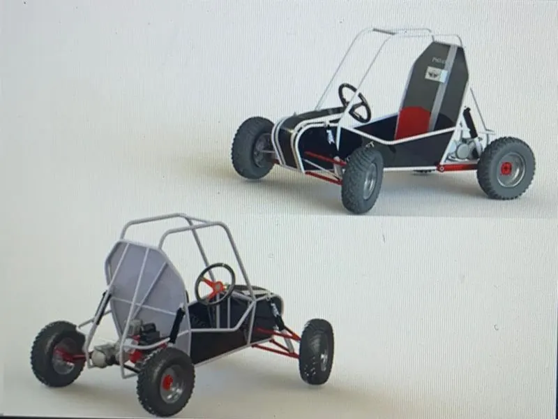
BAJA is basically an ATV competetion where students go design and develop a ATV model and is designed to run on various terrians such has sand, soil,gravel and pebbles.
As per the name ATV is designed to run and manover on different terrians or in other words we can say that ATV is designed especially for off roading purpose.
2.1 CONTINOUS VARIABLE TRANSMISSION (CVT) :
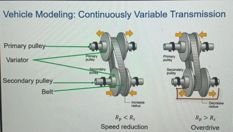
A Continous variable transmission is an automatic transmission that can change seamlessly through a continous range of gear ratio.this contrasts with other transmissions that provide a limited number of gear ratios in fixed step.The flexibility of a CVT with sutiable control may allow the engine to operate to operate at constant RPM while the vechile moves at variable speeds.CVT s are used automobiles,tractor,car,bikes and bicycle and also earth moving equipments.The most common type of CVT used two pulleys, chain ,variator however there are several other types are used at other times.
3. MODEL
This submission contain a serveral blocks made of simulink,simscape and simscape drivetrain most specifically the model contains BAJA ATV model and CVT model which is used in BAJA Competetion.This model shows how to build an ATV with CVT model in BAJA competetion simscape and simscape driveline are used to complete the system.The engine data used in the model is provided as an image which shows the engine speed(RPM) and speed curve.This is the open loop model of CVT.
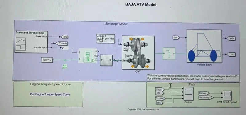
We can see in the above model the input for engine is acceleration.Then the engine was connected
and gave RPM input to the CVT.The secondary pulley of the CVT gave input to simple gear and then simple gear input to the vechile body block in the vechile body subsytem.All output from the system is given to output with the help of goto and from block.Input from the egine,CVT and vechile body from signal builder block.
MAIN COMPONENTS OF THE ATV SIMULATION:
Generic engine:
For engine here we used generic engine block.The generic engine block here is an internal combustion engine.This block here is used as spark ignition and diesel.Speed-power and Speed-torque are parameters are provided.A throttle physical input specifies the normalised engine engine torque.Optional dynamic parameters include crankshaft inertia and response time lag.A physical signal port outputs the engine fuel consumption rate based on the fuel consumption model that you choose.Optional speed and red line controllers prevent engine stall and enable cruise control.
The throttle input signal T lies between zero and one and specifies the torque demanded from the engine has a fraction of a maximum possible torque.
Connections F and B are mechanical rotational conserving ports assosiated with engine crankshaft and engine block respectively.Connections P and FC are physical input signal ports through which engine power and fuel consumption rate are reported.
Input for engine (signal builder)
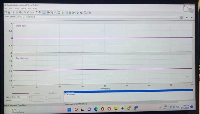
Throttle and breaking these are two inputs for engine,here signal builder is used to give input signal for engine
We can observe that currently there is no break input and constant throttle is provided in the system
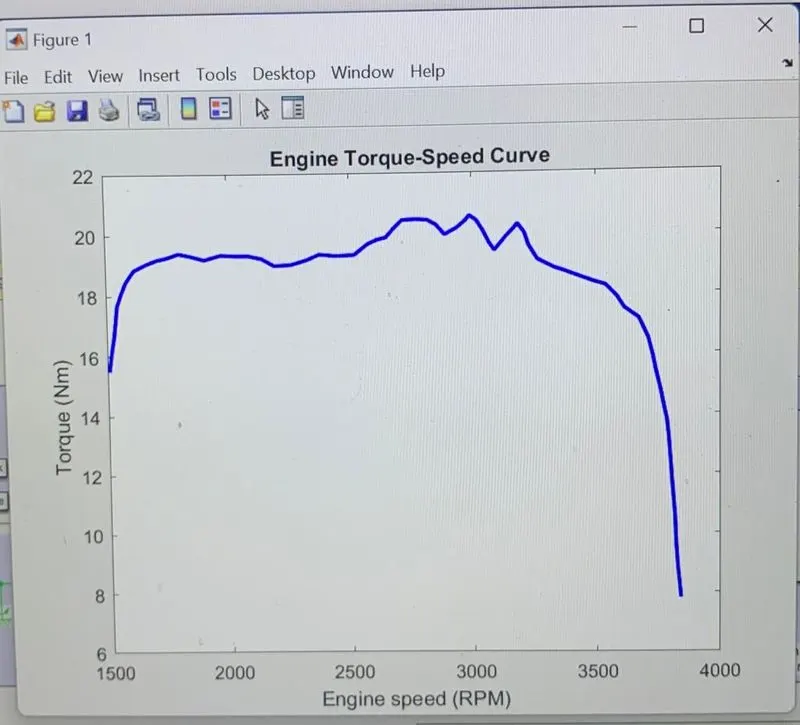
Here the data for engine speed and torque is extracted from the following image of speed and torque data with the help of GRABIT file exchange option.The function extracts the data point from image and saved in workspace to use.
GRABIT : information source
Engine sensor :
Engine sensor is ideal rotational motion sensor block represents an ideal mechanical rotational motion sensor,that is a device that converts an across variable measures between two mechanical rotational nodes into a control signal proportional to angular velocity or angle.You can specify the initial angular position as a block parameter.
The sensor is ideal since it does not account for inertia,friction delays,energy consumption and so on.Connections R and C are mechanical rotational conserving ports that connnects the block to the nodes whose notion is being monitered.Connections W and A are physical signal output ports for the velocity and angular displacment respectively.
The block direction is from port R and port C.this means velocity is measured has w =wR-wC where wR and aC are the absolute angular velocities at port R and C respectively.
CVT subsystem
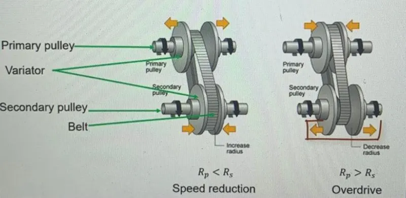
Here we are using gear reduction drive which is lower speed instead oof overdrive we can see the following differeneces.
Here we are using gear reduction drive which is lower speed of overdrive you can the difference in the following image
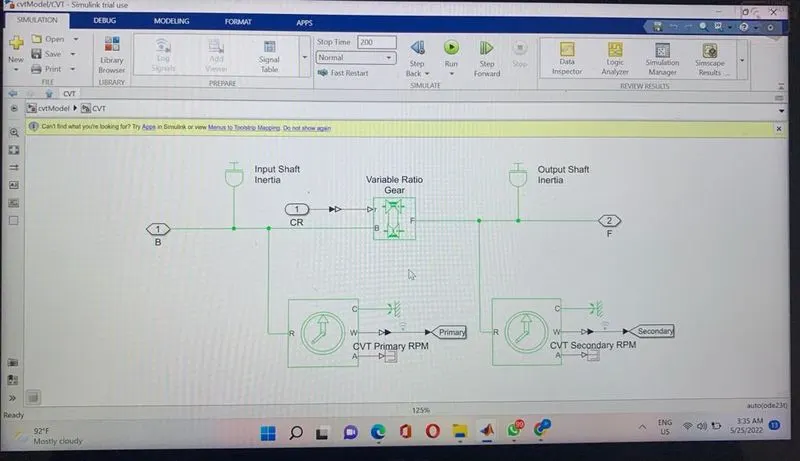
For CVT there is no block created a subsystem is created,which contains the following blocks
1. Goto :Send signals to from block that have the specified tag.If tag visability is scoped then goto visibility is must be used to define the visability of the tag.The block icon displays the selected tag name.
2.Inport: Provide an inport for the selected model.
3.Inertia :The block represents an ideal mechanical rotational inertia.
4.PMC_port:Physical modelling port for the subsystem or model.
5.Variable ratio gear transmission:Represents a variable ratio gearbox such has impelemted by the mechanical, belt,electric or hydraulic transmission.The physical signal r defines the ratio of the output to the input angular shaft velocities connections B and F are mechanical rotational conserving ports specify the relation between the base and the follower rotation direction with the output shaft rotation parameter.
6.Ps terminator:Use this block to terminate physical signal outputs,Unconnected physical signals do not generate warnings,But connection to a ps terminator can be used to indicate that the signal was no inadvertly left unconnected.
7.Mechanical rotational reference:This block represents a mechanical rotational reference point,that is a fame or a ground Use it to connect the mechanical rotational part that are rigidly affixed to the frame.
8.Ps -simulink converter: converts the physical signal to simulink converter.
The unit expression in Output signal unit parameter must match or to be commesurate with the unit of the physical signal and determines the conversion of physical signal to simulink output signal.
5.Input for CVT :
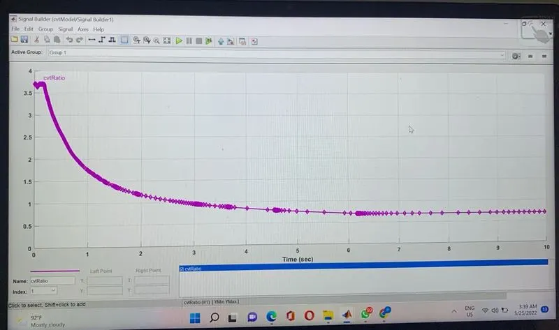
The input for CVT subsytem is the CVT ratio and engine rpm.Engine RPM we discuss above and CVT ratio is given by signal buidler.
Simple gear :
Represents a fixed ratio gear or gearbox.No inertia or compliance is modelled in this block.You can optionally include a gear meshing,blacklash and viscous gearing losses.Connections base and Follower are mechanical rotational conserving ports specify the relation between the base and follower rotation directions with the output shaft rotates parameter.Optionally include thermal effects and expose thermal conserving port H to a frictional model to a temperature dependent setting
With the current vehicle parameters the model is designed with gear ratio=10 For different vehicle parameters you need to tune the gear ratio.
To connect the engine and CVT we need to speed reduction to add simple gear block
Vechile body subsystem :
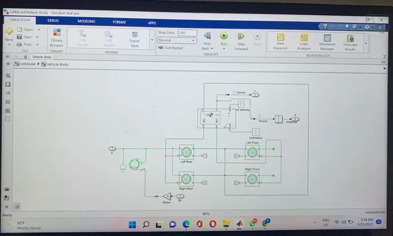
The above model is the graphical representation of vehicle frame and wheel
Vehicle Body:Represents a two axle body of longitudnal motion.The block accounts for body mass,aerodynamic drag,road incline and weight distribution between axles due to acceleration and road profile.The vehicle can have same or different number of wheels on each axle optinally include pitch and suspension dynamics or additonal mass and inertia the vehicle does not move vertically relative to ground.
Connection H is the mechanical translational conserving port assosiated with the horizonatal motion of the vehicle body.The resulting traction motion developed by the tyres should be connected to this port.Connections V,NF and NR are physical signal output ports for vehicle velocity and fornt and rear normal wheel forces are considered positive if acting downwards connections W and beta are physical signal input forces corresponding to headwing speed and road inclination angle respectively.If variable mass m is modelled the physical signal input ports CG and M are exposed CG accepts two element vector representing x and y distance accepts from vehicle CG to additional load mass CG.M represnts the additional mass if both the variable mass and pitch dynamics are included,The physical signal port J accepts the inertia of the additional mass about its own CG.
Tire(Magic formula)
Represents the longitudnal behaviour of a highway tire characterized by the magic formula.The block is build from tire road interaction and simscape foundation library wheel and axle blocks,Optionally the effects of tire inertia,stiffness,and damping can be included.
Connection A is a mechanical rotational conserving port for the wheel axle.Connection H is the mechanical translational conserving port for the wheel hub through which the thrust developed by the tire is applied to the vehicle.Connection N is a physical signal output port that reports the tire slip.Optionally expose physical signal port M by connecting the parametarize by the physical signl magic formula coefficients.Physical signal port M accepts a four-element vector corresponding to BCD and E magic formula coefficients.
Double Shoe Brake :
Represents a brake arranged has pivoted rigid shoes symmetrically installed inside or outside a drum and operated by an acutator.The acutator force causes the shoe to exert a friction torque on a shaft connected to the drum.
Connection S is a conserving rotational terminal assosiated with the drum shaft.Connection F is physical port representing the force input to the acutator.Positive force creates friction torque that resists shaft rotation.Optionally include thermal effects and expose thermal conserving port H by setting thermal port to model
OUTPUT RESULTS:
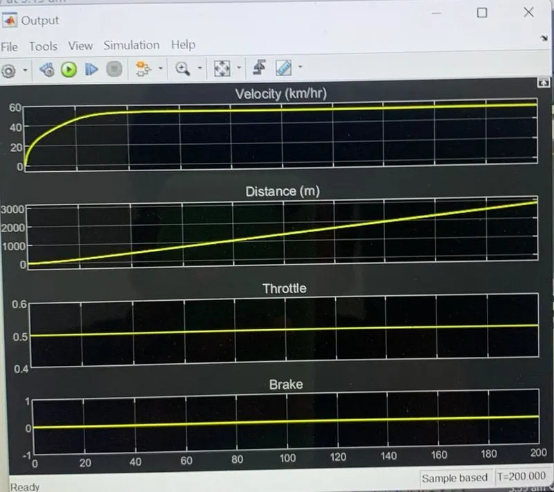
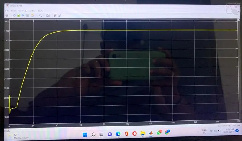
In the above graph velocity increases overtime 40 sec but after that it will be constant we cover a 3km distance with 0.5 throttled input and no brake applied.
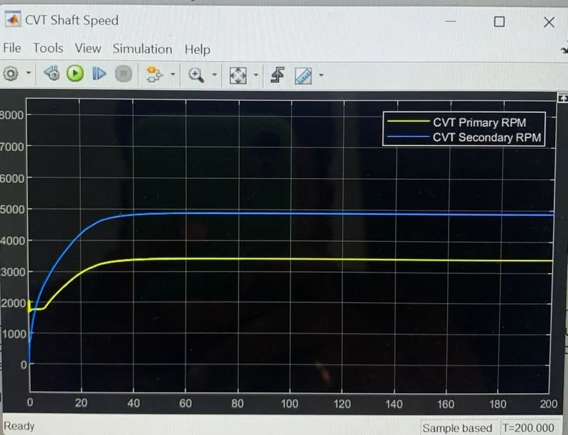
Here we can see that the secondary pully RPM is greater than the primary pully RPM because when we accelerate the vehicle the primary pully expands will extract this process is nothing but speed reduction.
5.MODEL CVT dash board :
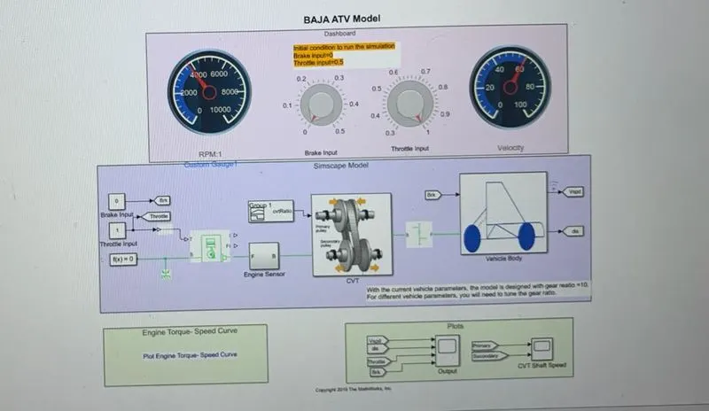
In this model we are used the same model but with different input in running time for actual simulation with help of different block other parameters are all same.T o give input dashboard knobs are used which are connected constant block which provide input in running time.We give infinite time for running so we can change the speed and observe the results.This is an open loop for CVT.
Conclusion :
Therefore the study of BAJA all terrian ATV vehicle atv model is done sucessully and the results are displayed above and also the elements included in it are also studied.