Project
- AIM: To investigate the simulation of an all-terrain vehicle at the system level.
CVT, lookup table, Dashboard, and Baja ATV
APPLICATIONS: Matlab, Simulink
OBJECTIVE:
1. Examine the Baja ATV without the dashboard.
2. Examine the Baja ATV with the dashboard model.
3. Use a lookup table without a dashboard to study the Baja ATV model.
4. Use a lookup table and dashboard to research the Baja ATV model.
INTRODUCTION: Transmission, which sends power from the engine to the wheels through shafts. It is divided into four categories. mainly,
Transmission: manual
Variable transmission indefinitely
The transmission is semi-automatic.
Transmission is automatic.
A CVT is a form of automatic transmission that gives more usable power, better fuel economy, and a smoother driving experience than a typical automatic transmission. The CVT is a mechanism that allows you to change the gearbox ratio steplessly without interrupting the torque flow. As a result, there are an endless number of ratios (between a minimum and maximum value). It's a single-speed, gearless automatic transmission that can shift through an endless number of gear ratios. This ability to smoothly shift between gears has a lot of advantages, including incredibly smooth shifts and excellent fuel economy. A CVT extracts maximum power from a small engine, allowing drivers to accelerate more quickly than with a regular automatic transmission.
STUDY 1:-
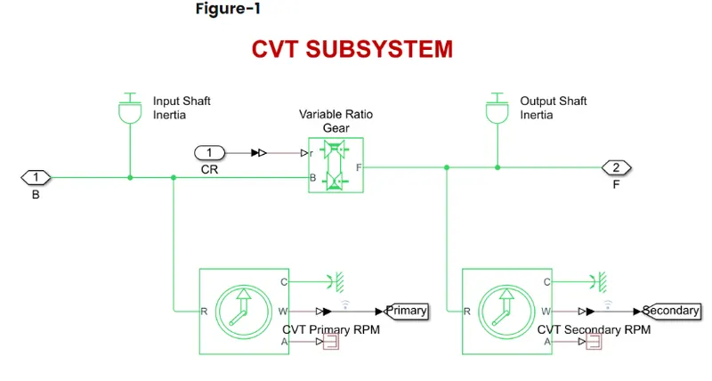
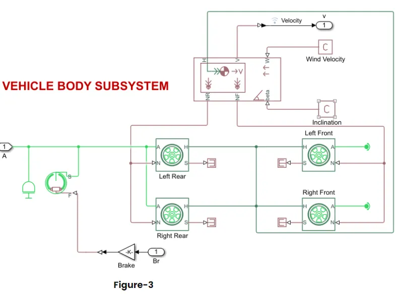
Using the Simulink model of CVT consists of a Signal builder, generic engine, motion sensors, vehicle transmission, vehicle body, tyres and solver configuration blocks etc., as shown in figure-1. The CVT subsystem includes Transmission block, input and output shaft inertia and motion sensors as shown in figure-2. The vehicle body subsystem includes a vehicle body block, double drum brake and tyres as shown in figure-3. The initial engine speed is given as 2100 rpm, and mechanical rotation for the driven pulley and driver pulley is 0.8 & 0.7 respectively. The mass of the vehicle is 250kg and 2 axles connect 4 wheels accordingly.
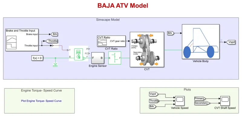
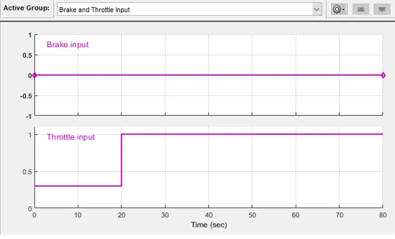
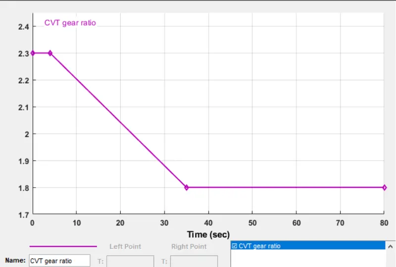
The brake, throttle, and gear ratio are all controlled by the signal builder. For the sake of simulation, the brake input is set to zero. The throttle input is set to 0.3 for 20 seconds and then to 1 for the entire simulation. The throttle valve's primary function is to regulate the flow or amount of gasoline entering the engine; as the throttle value rises, the flow of fuel into the IC engine rises, increasing the engine's power. As illustrated in the figure, the gear ratio is maintained at 2.3 for 5 seconds before decreasing linearly to 1.8 and remaining constant throughout the simulation (4 - 5).
STUDY 2-
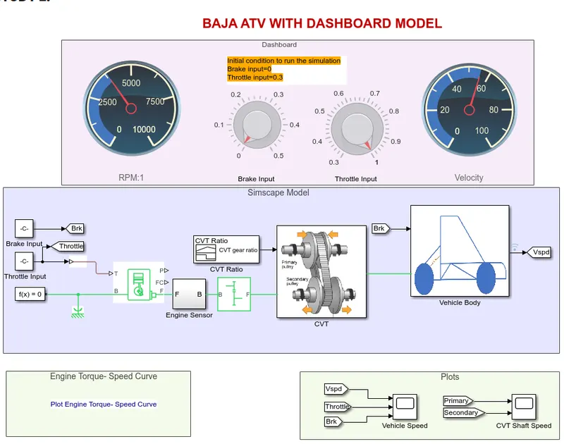
Instead of delivering input through the signal builder, the 'Baja ATV with dashboard' model has a throttle metre and brake input on the dashboard. Figures 2 and 3 show the rest of the blocks and subsystems in the aforementioned Baja ATV model minus the dashboard. The fundamental idea behind employing a dashboard is to examine the results by altering the brake and throttle inputs, which depict the engine's velocity and speed. As seen in figure 5, the gear ratio is maintained at 2.3 for 5 seconds before decreasing linearly to 1.8 and remaining constant throughout the experiment. The velocity and speed decrease when the brake input fluctuates between 0 and 0.5. The throttle can be increased the velocity and speed of the engine & shaft increase.
STUDY 3-
As illustrated in figure-7, the CVT model is made up of step time, generic engine, motion sensors, vehicle transmission, vehicle body, tyres, and solver configuration blocks. Figure 8 depicts the CVT subsystem, which contains the lookup table, transmission block, input and output shaft inertia, and motion sensors. Figure 9 depicts the vehicle body subsystem, which includes the vehicle body block, double drum brake, and tyres. The initial engine speed is 2100 rpm, with mechanical rotations of 0.8 and 0.7 for the driven and driving pulleys, respectively. The vehicle weighs 250 kg and has two axles that link the four wheels.
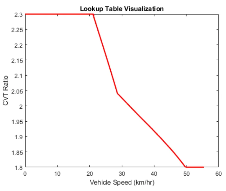
A lookup table is an array of data that maps input values to output values, thereby approximating a mathematical function. Given a set of input values, a lookup operation retrieves the corresponding output values from the table. If the lookup table does not explicitly define the input values, Simulink can estimate an output value using interpolation, extrapolation, or rounding, where:
Interpolation is a process for estimating values that lie between known data points.
Extrapolation is a process for estimating values that lie beyond the range of known data points.
Rounding is a process for approximating a value by altering its digits according to a known rule.
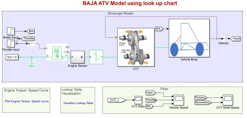
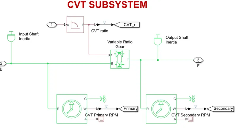
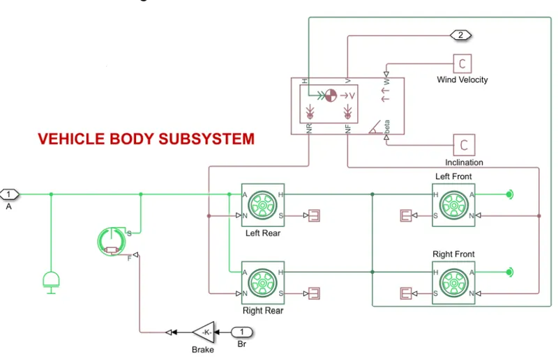
As illustrated in figure-7, the CVT model is made up of step time, generic engine, motion sensors, vehicle transmission, vehicle body, tyres, and solver configuration blocks. Figure 8 depicts the CVT subsystem, which contains the lookup table, transmission block, input and output shaft inertia, and motion sensors. Figure 9 depicts the vehicle body subsystem, which includes the vehicle body block, double drum brake, and tyres. The initial engine speed is 2100 rpm, with mechanical rotations of 0.8 and 0.7 for the driven and driving pulleys, respectively. The vehicle weighs 250 kg and has two axles that link the four wheels at 57 km approximately
STUDY 4:-
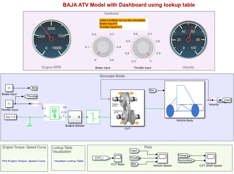
The 'Baja ATV with dashboard' model is shown above utilising a lookup table that includes a throttle metre and brake input in the dashboard and is denoted as a constant block. Figures 8 and 9 show the rest of the blocks and subsystems in the aforementioned Baja ATV model minus the dashboard. The fundamental idea behind employing a dashboard is to examine the results by altering the brake and throttle inputs, which indicates how the engine's velocity and speed change. The gear ratio is determined by a lookup table, and Simulink uses the lookup table to acquire the input value and the result. The velocity and speed drop as the brake input varies from 0 to 0.5, which in turn the gear ratio also decreases. By increasing the throttle, the velocity and speed of the engine & shaft increase. The transmission is a primary pulley and secondary pulley, in which the radius of the primary pulley increases by compacting and the radius of the secondary pulley decreases. As the gear ratio varies, the torque also varies. The gear ratio is directly proportional to the torque, which increases by increasing the gear ratio. At the max torque, the speed and velocity decrease.
OUTPUT:
Study 1:- Variation of velocity & Shaft speed
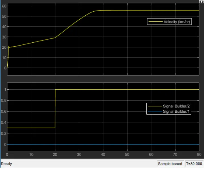
The brake is kept constant in the preceding diagram, but the throttle is increased, indicating an increase in velocity. When the throttle is increased from 0.3 to 1, the flow of fuel rises, and the engine's power increases. At a 1.8 gear ratio, the torque reaches around 7N-m, indicating that the gear ratio is directly proportional to the torque. The highest speed and velocity can be achieved with this gear ratio.
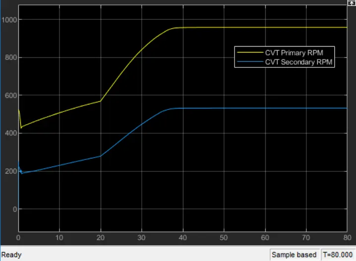
In the above figure, the primary shaft reaches high speed and the secondary shaft has low rotational speed because the radius of the
primary shaft as more than the secondary shaft, and the speed is directly proportional to the radius of the shaft. As the radius increases
the speed of the shaft also increases.
Study 2:- Variation of velocity & Shaft speed
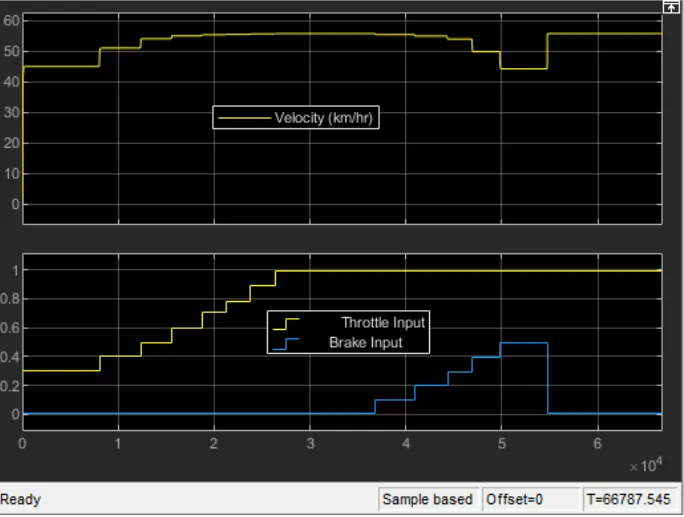
In the above figure, the velocity of the vehicle is maintained as constant for a constant throttle value of 0.3 and varies by increasing the value of throttle which increases the velocity of the vehicle. By increasing the brake input, the velocity of the vehicle decreases accordingly which is shown in figure14.
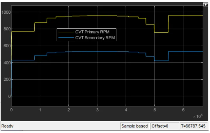
n the above figure, the primary shaft speed increases by increasing throttle and decreasing by increasing brake input value, which
defines that the throttle can flow more amount of fuel which increases the power of the engine and is similar to the secondary shaft.
The radius of the primary shaft as more than the secondary shaft, and the speed is directly proportional to the radius of the shaft. As the
radius increases the speed of the shaft also increases.
Study 3:- Variation of velocity & Shaft speed
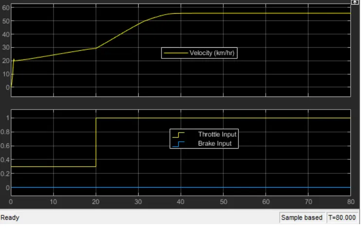
In the above figure, the brake is maintained as constant and increases in throttle which shows an increase in velocity. The flow of fuel
increases when the throttle increases from 0.3 to 1, thus the power in the engine increases. The torque reaches approximately 7N-m at
1.8 gear ratio, which defines that the gear ratio is directly proportional to the torque. By this gear ratio, the speed & velocity can achieve
maximum. The gear ratio is assigned in the lookup table and given as input to the Simulink which reads every input value and obtains the
result according to the input.
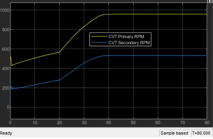
In the above figure, the primary shaft speed increases by increasing throttle and decreasing by increasing brake input value, which
defines that the throttle can flow more amount of fuel which increases the power of the engine and is similar to the secondary shaft.
The radius of the primary shaft as more than the secondary shaft, and the speed is directly proportional to the radius of the shaft. As the
radius increases the speed of the shaft also increases.
Study 4:- Variation of velocity & Shaft speed
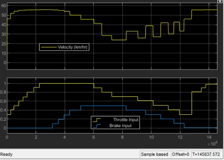
The vehicle's velocity is kept constant in the above figure for a constant throttle value of 0.3 and varies by increasing the throttle value, which increases the vehicle's velocity. The velocity of the vehicle decreases as the brake input is increased, as seen in figure 18. We can get any particular value of gear ratio that is beyond the range or any random value within the range by applying extrapolation and interpolation via a lookup table, which acts as a closed loop by storing the velocity value.
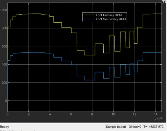
In the diagram above, the main shaft speed increases as the throttle are increased and decrease when the brake input value is increased, indicating that the throttle may flow more fuel, increasing the engine's power, and is comparable to the secondary shaft. The primary shaft has a larger radius than the secondary shaft, and the speed is proportional to the radius of the shaft. The speed of the shaft increases as the radius increases. The throttle and brake input values in the dashboard can be changed, allowing us to get any input value we want.
CONCLUSION:
1. As the throttle increases, the velocity also increases which in turn the power in the engine increases.
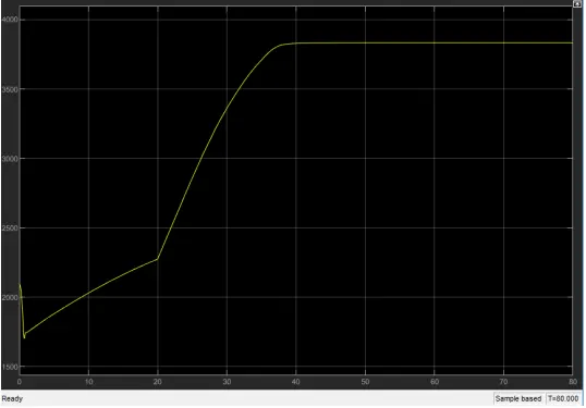
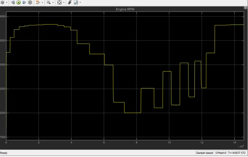
In the above figure, in the beginning, the speed reduces because of gear ratio and torque output. When the gear ratio increases, the
torque increases.
2. As the brake input increases, the velocity decreases and engine power also decreases. At a certain brake input value the engine
may shut down and there is no power output. The engine power is inversely proportional to the brake input.
3. As the gear ratio increases, torque increases which in turn velocity decreases.
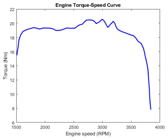
In the above figure, the torque is increasing by an increase in engine speed. At a particular point the torque is decreasing when the
gear ratio increases to achieve maximum velocity.
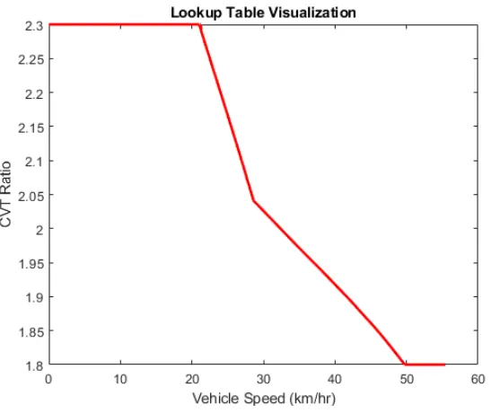
In the above figure, the velocity is varying wrt the gear ratio. For the high gear ratio, the torque is more which decreases the velocity. By
changing to high gear, the gear ratio becomes less parallel the torque also less which can get high velocity.
4. With help of a lookup table, we can vary any input value and also get the output value by using interpolation and extrapolation
the method which the Simulink can solve.