Project
AIM : To understand all model of BAJA ATV by carrying out system-level simulation.
OBJETIVE:
- To carry out a system level simulation of all -terrain vehicle.
- To prepare a technical report explaining the model properties and outputs.
THEORY :
BAJA ATV :
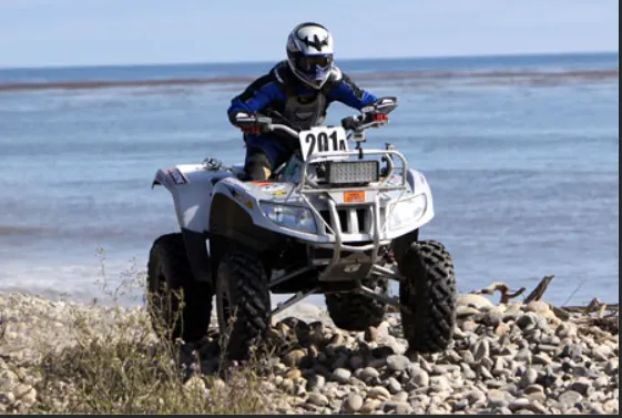
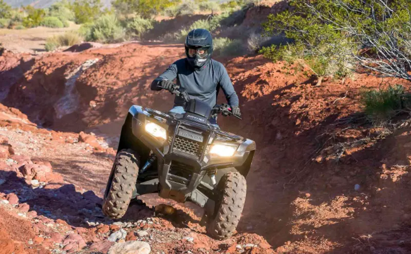
- BAJA is basically an ATV (all terrain vehicle) competition where students gets to design and develop their own ATV keeping in mind various considerations of design as well as safety . An ATV is design in order to run on various terrain such as soil, Gravel , Pebbles , etc .
- It is organised by the society of Automotive Engineers , USA.
- The BAJA SAE tasks the student to design ,fabricate and validate a single seater four-wheeled off road vehicle to take part in series of events spread over a course of 3 days that test the vehicle for differnt conditions.
- An ATV is a motorized single-seated tri r quardricycle bike and buggy that is designed for off road travel and activities.
- these vehicles consist of handlebars and low-pressure tires that have deep- threaded structure , which assist in driving over muddy , rocky ,wetlend etc.
CONTINUOUSLY VARRIABLE TRANSMISSION (CVT) :
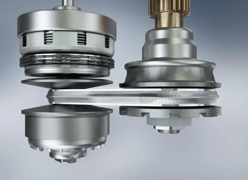
- A CVT , or continuously variable transmission , seamlessly changes through an unending range of effective gear ratios while you drive , whereas other kinds of mechanical transmissions offer a fixed number of gear ratios and have hard shifts between each .
- CVT transmission system are also known as single-speed , shiftless , and stepless transmissions .
- The shiftless nature of a CVT offers unparalled flexibility that maintains constant angular velocity regardless of output speed . Additionally , a continuously variable transmission makes accelerating smooth and offers enhanced fuel economy.
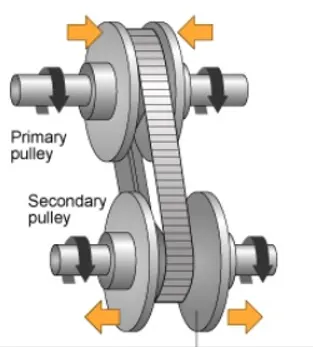
- while a traditional transmission uses a wide variety of intricate parts to shift between a range of present gears,most CVT system works through a pulley system .
- This system consists of cones at each pulley connected via a chain belt.
- The cones can move to increase or decrease the belt diameter to change gear ratios , allow for quick shifting into the needed ratio for increased power , and boost fuel economy.
- One pulley in the CVT is connected to the engine and the other directs power to the wheels . The width of these pulleys changes based on the needed power ; as one gets larger , the other gets smaller . This allows a CVT to deliver strong and seamless acceleration .
Various model BAJA ATV are as follow :
- BAJA ATV model without dashboard.
- BAJA ATV model with dashboard.
- BAJA ATV model with lookup table and without dashboard .
- BAJA ATV model with lookup table and with dashboard.
1 ) BAJA ATV Model without dashboard :
- This is the simplest model of BAJA CVT model .
A simulink model for the baja ATV model is shown below :
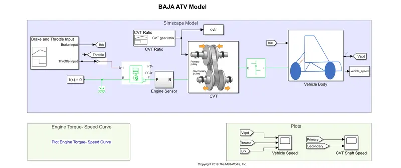
The model consist of main blocks are as follow :
Signal Builder :
The signal builder block allows you to create interchangeable groups of piecewise linear signal sources and use them in a modle .
Generic Engine :
- Represent a system - level model of spark - ignition and diesel engines suitable for use at initial stages of modeling when only the basic parameters are available . Optional idle speed and red line controller are included .
- The throttle input signal T lies between zero and one and specifies the torque demanded from the engine as a fraction of the maximum possible torque . If the engine speed falls below the stall speed , the engine torque is blended to zero . If the engine speed exceeds the maximum speed , the simulation stops and issues an error message .
- connection F and B are mechanical rotational conserving ports associated with the engine crankshaft and engine blocks, respectively . Connections p and FC are physical signal output ports through which engine power and fule consumption rate are reported.
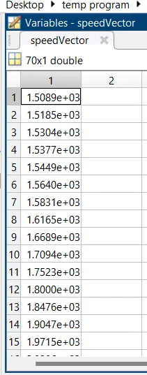
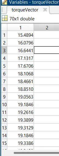
Speed vector and torque vector are assigned parameters :
Simple Gear :
- Simple gear of base and follower wheels with adjustable gear ratio , frictional losses and triggered faults .
- The simple gear block represents a gearbox that constrains the connected driveline axes of the base gear B and follower gear F , to corotate with a fixed ratio that you specifies.You choose whether the follower axis rotates in the same or opposite direction as the base axis . if they rotate in the same direction , the angular velocity of the follower and angular velocity of the base have the same sign . If they rotate in opposite directions , it will have opposite sign .
- Represents a fixed - ratio gear or gear box . No inertia or compliance is modeled in this block you can optionally include gear meshing and viscous bearing losses.
- Connections B (base ) and F (follower ) are mechanical rotational coserving ports . Specify the relation between base and follower rotation directions with the output shaft rotates parameter . Optionally includes thermal effects and expose thmal conserving port H by setting friction model to a temperature - dependent setting .
Engine sensor subsystem :
RPM Sensor :
- The ideal rotational motion sensor block represents an ideal mechanical rotational motion sensor , that is , a device that convert an across variable measured between two mechanical rotational nodes into a control signal proportional to angular velocity or angle . You can specifie the initial angular position ( offset ) as a block parameter.
- The sensor is ideal since it does not account for inertia , friction , delays , energy consumption , and so on .
- Connection R and C are mechanical rotational conserving ports that connect the block to the nodes whose motion is being monitered . connection W and A are physical signal outputs ports for velocity and angular displacement , respectively .
- This block measure angular velocity or angle in a mechanical rotational network . The sensor is ideal since it does not account for inertia , friction , delays , energy consumption and so on .
- The physical signal ports W and A report the angular velocity and angle , respectively , of port R relative to port C . The measured angular velocity is positive when the angular velocity at port R is greater than the angular velocity at port C .
Subsystem of CVT :
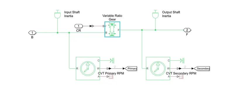
Input shaft inertia and output shaft inertia :
- Input shaft inertia generally represent the primary shaft of CVT.
- output shaft inertia generally represent the secondary shaft of CVT.
- The block represent an ideal mechanical rotational inertia .
- The block has one or two mechanical rotational conserving ports . The difference is purely graphical , as the port are rigidly linked . The block positive direction is from its port to the reference point . This means that the inertia torque is positive if the inertia is accelerated in the positive direction .
Variable Ratio Gear :
- Dynamic gearbox with variable and controlled gear ratio , transmission compliance and friction losses.
- The variable transmission block represent a gearbox that dynamically transfer motion and torque between the two connected driveshaft axes , base and follower .
- Ignoring the dynamic of transmission compliance , the driveshafts are constrained to corotate with a variable gear ratio that you control .
- Ports B and F are rotational conserving ports representing respectively , the base of follower driveshafts.
Subsystem of vehicle body :
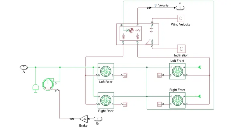
Double -shoe brake:
- Frictional brake with two pivoted shoes diametrically positioned about a rotating drum with triggered faulting .
- Represents a breake arranged as two pivoted rigid shoes symmetrically installed inside or outside a drum and operated by one actuator . The actuator force causes the shoes to exert a friction torque on a shaft connected to the drum .
- connection S is a conserving rotational terminal associated with the drum shaft . Connection F is a physical signal port representing the force input to the actuator . Positive force creates friction torque that resists shaft rotation . Optionally includes thermal effects and expose thermal conserving port H by setting thermal port to model .
- The double - shoe bake block represent a frictional brake with two pivoted rigid shoes that press against a rotating drum to produce break action . The rigid shoes sit inside or outside the rotating drum in a diametrically opposed configuration .A positive actuating force causes the rigid shoes to press against a rotating drum . Viscous and contact friction between the drum and the rigid shoe surface cause the rotating drum to decelerate .
- Double - shoe brakes provide high braking torque with small actuator deflections in application that include motor vehicle and some heavy machinery . The modle employs a simple parameterization with readily accessible brake geometry and friction parameters.
- You can also enable faulting . When faulting occurs, the belt will exert a user - specified force . Faults can occur at a specified time or due to an external trigger at port T .
Vehicle Body :
- Two -axle vehicle with longitudinal dynamics and motion and adjustable mass , geometry and drag properties.
- Represents a two - axle vehicle body in longitudinal motion .The block account for the body mass , aerodynamics drag, road incline , and weight distribution between axles due to acceleration and road profile . The vehicle can have the same or a different number of wheels on each axles. optionally include pitch and suspension dynamics or additional variable mass and inertia. The vehicle does not move vertically relative to the ground .
- Connection H is the mechanical translational conserving port associated with the horizontal motion developed by tires should be connected to this port . Connections V,NF, and NR are physical signal output port for vehicle velocity and front and rear normal wheel forces , respectively . Wheel forces are considered positive if acting downwards . connections W and beta are physical signal input port corresponding to headwind speed and road inclination angle , respectively . If variable mass is modeled , the physical signal input ports CG and M are exposed .CG accepts a two - element vector representing the x and y distance offsets from vehicle CG to additional load mass CG . M represent the additional mass . if both variable mass and pitch dynamics are included , the physical signal port J accepts the inertia of the additional mass about its own CG.
- The vehicle body represents the two -axle vehicle body in longitudinal motion . The vehicle can have the same or a different number of wheels on each axle . For example ,two wheels on the front axle and one wheel on the rear axle . The vehicle wheel can also have a center of gravity that is at or below the plane of travel .
Tire ( Magic formula ) :
- Tire with longitudinal behavior given by magic formula coefficients.
Represents the longitudinal behavior of a highway tire characterized by the tire magic formula . The block is built from tire- Road interaction and simscape foundation library wheel and axle blocks . optionally , the effects of tire inertia , stiffness and damping can be included .
connection A is the mechanical rotational conserving port for the wheel axle .
connection H is the mechanical translational conserving port for the wheel hub through which the thrust developed by the tire is applied to the vehicle .
connection N is aphysical signal input port that applies the normal force acting on the tire .
Explanation :
- The throttle signal is generated by signal builder block and inputted to generic engine.
- The torque and speed vector are inputted from matlab workspace.
- now from crankshaft output ,the value is passed to engine .
- the speed is sense by ideal rotational motion sensor .
- The output speed will be given to a simple gear mechanism to reduce the speed where the gear ratio is four.
- The output speed from the gear reducer will be given to the CVT .
- the CVT ratio is provided to the CVT block through signal builders.
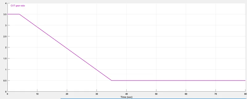
- The speed is controlled by the variable CVT ratios and the controlled output speed is inputted to the vehicle axle.
- The power from CVT is inputted to the axle and the vehicle accelerated according to the speed .
- Then the velocity is taken as output from the vehicle body for further analysis .
INPUTS :
Torque - speed plot :
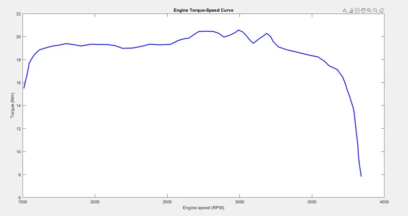
- It is taken as default input to the engine.
- The torque and speed are inputted from the matlab workspace window to the generic engine block to generate the output RPM accordingly .
BREAKE INPUT AND THROTTLE INPUT :
Here the break input is given as 0.
and throttle velocity is is given 0.3 for 30 sec and for 1 after 30 sec and it remains constant .
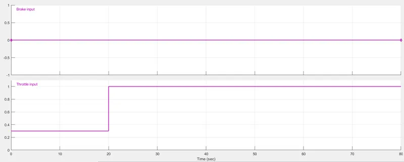
OUTPUTS :
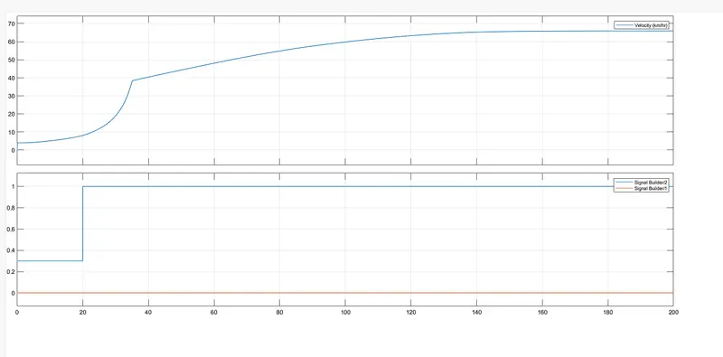
- From the graph we can see that the brake value is zero throughout the simulation process.
- Throttle velocity is remain constant and is 0.3 for 20 sec.
- After 20 sec ,throttle value becomes 1 and is remain constant after 20 sec .
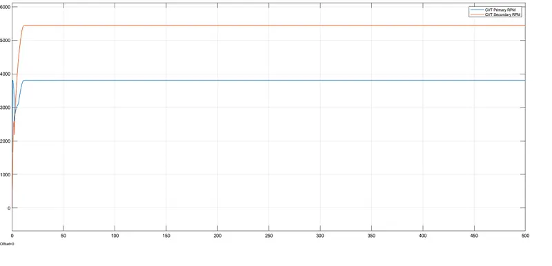
Primarry shaft and Secondary shaft velocity comparision :
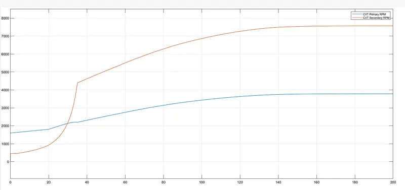
- As we can see from the graph that , velocity of secondary shaft is greater than the velocity of secondary shaft .
2 ) BAJA ATV model with dashboard :
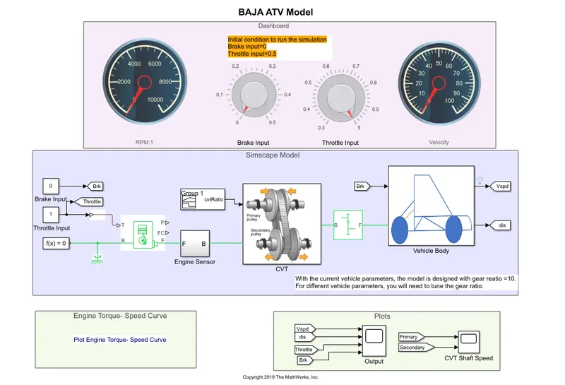
- In this model ,there is only change that we can give break input and throttle input through knob.
- we are replacing signal builder with two seperate constant blocks for throttle and brake .
- All other procedure is same .
CASE 1:
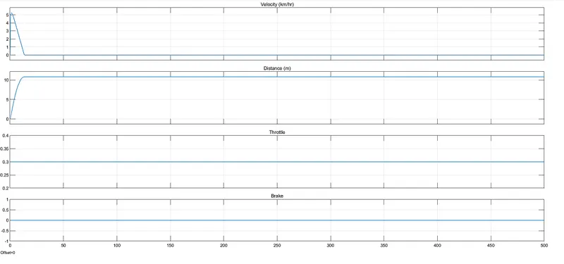
THROTTLE VELOCITY IS 0.3
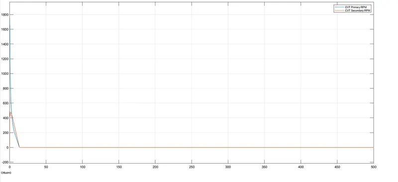
- As we can see from the graph that due to low throttle value , velocity becomes zero after some sec .
CASE 2:
THROTTLE VELOCITY IS 0.6
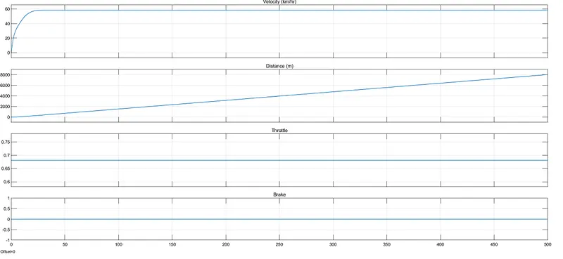
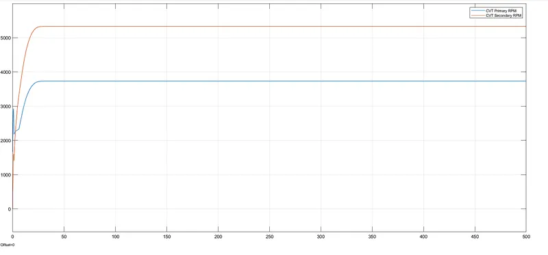
- Here from graph we can see that as we have increase throttle valve , speed increase and remain constant at 60 .
CASE 3:
THROTTLE VELOCITY IS 1
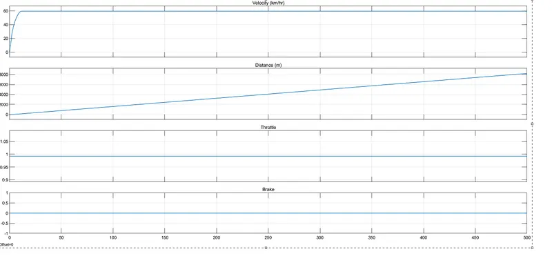
- Here we have given maximum value of throttle ie 1 .
- Velocity increases rapidly and become constant .
- Maximum velocity is 58 kmph.
3 ) BAJA ATV model with lookup table and without dashboard .
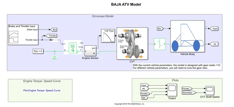
In this model lookup table is added .
Flow process :
- In this model lookup table is added in the subsystem of CVT block.
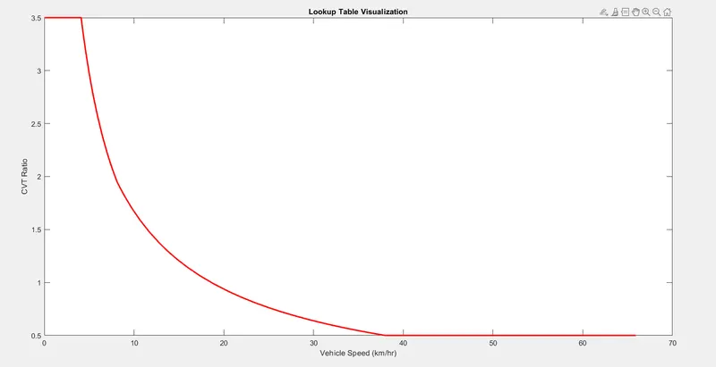
- CVT ratio and vehicle speed are extracted from matlab workspace.
Lookup Table :
- A loopup table is an array of data that maps input values to output values , thereby approximating a mathematical function .
- Given a set of input values , a lookup operation retrive the corresponding output values from the table .
- If the lookup table does not explicitly define the input values , simulink can estimate an output value using interpolation , extrapolation or rounding .
4 )BAJA ATV model with lookup table and with dashboard :
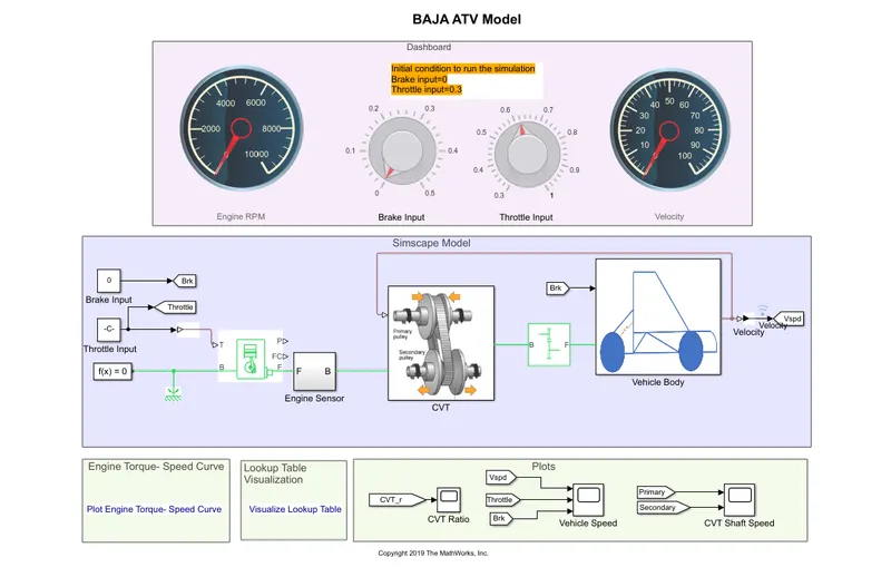
- This is the latest upgraded model of BAJA ATV model.
- In this model both dashboard and lookup table is used .
OUTPUTS :
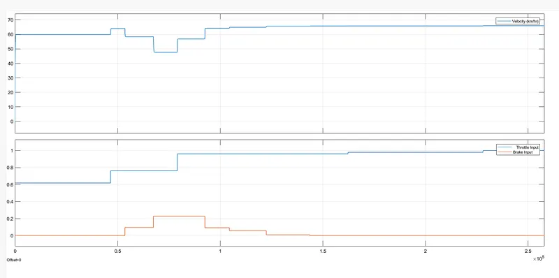
Case 1 :
- Here we have given random value of throttle and brake inputs .
- AS seen from graph , the value of speed is changing accordingly.
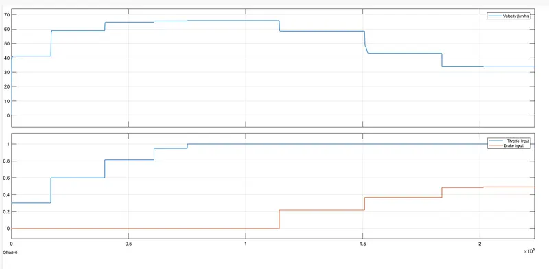
Case 2 :
- Here we first increasing value of throttle input to its maximum value.
- Now increasing the brake value to its maximum values.
- The below graph shows the variation of speed according to above condition .
Output of Primary shaft and secondary shaft :
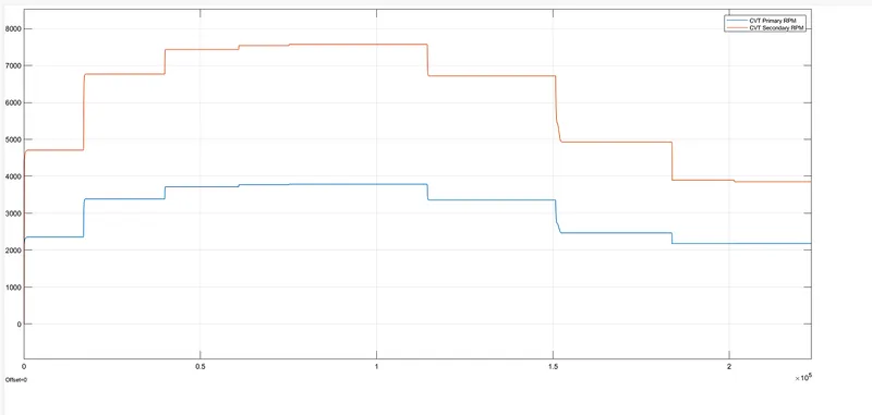
- From the above graph we can see that ,shaft speed in rpm increase upto 7500rpm at throttle value of 1 and break input of 0.
REFERENCE:
https://www.mathworks.com/matlabcentral/fileexchange/70576-baja-all-terrain-vehicle-atv-model