Project
aim : to observe the performance of all-terrain vehicle's speed and torque with respect to change in throttle and brake as input of continuosly variable transmission engine by using simulink model.
all-terrain vehicle is a small open motor vehicle which has one seat and three or more wheels fitted with large tyres. it is specially designed for use on rough ground. this vehicle uses the CVT engine.
a continuously variable transmission (CVT) engine is an engine which doesn't have any gears instead of it contains to pulleys connected by a belt. One pulley is connected to the engine and another is connected to the transmission. the belt transfers the moment in between them.
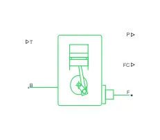
the fuel combustion is done inside the generic engine. the generic engine block represents a general internal combustion engine. the physical input to the generic engine is throttle which is responsible for speed-torque and speed-power characterstics of vehicle. the output of the generic engine is power (P) and fuel consumption (FC).
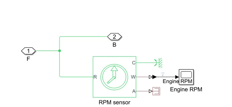
here the generic engine transfers the power to the pulley. we need to observe the angular velocity of the shaft so that we need a RPM sensor. the output of rpm sensor is angular velocity and it is recorded by using a scope.
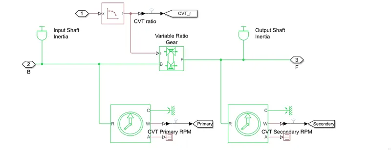
the above picture represents the CVT engine's primary and secondary shaft arrangement. it has two ideal rotational arrangements which also senses the RPM of them. the input shaft drives the output shaft by help of belt. the inertia of input shaft and output shaft is adjusted to m1*(((18.6e-2)/2)^2+((2.5e-2)/2)^2)/2 and m2*(((19.8e-2)/2)^2+((1.9e-2)/2)^2)/2 respectively. here the value of m1 and m2 is specified in a matlab script as 3.5 and 3.2 respectively.
the CVT engine's primary shaft and secondary shaft is connected by means of variable ratio transmission. the input to the variable ratio transmission is the value of ratio of vehicle speed and 3.6 .

simple gear is a gear which is connected in between of vehicle and CVT engine as shown in above figure. it also consists of follower(F) to base(B) teeth ratio and it is adjusted to 12.
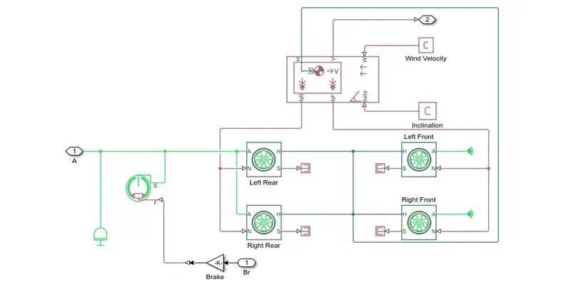
if we come to the vehicle body, total arrangement and connections to the wheels are able seen in this class. the phhysical connection of rear and front tyres to the body connected my means of NF and NR. to apply brake to a vehicle we need to connect a brake shoes. the input of the brake shoes is variable brake moment and output is connected to rear wheels. the physical standard part of vehicle connected to wheels is "H". "V" port is the velocity port and "W" is the wind velocity input and beta is the angle at which the vehicle is moving.
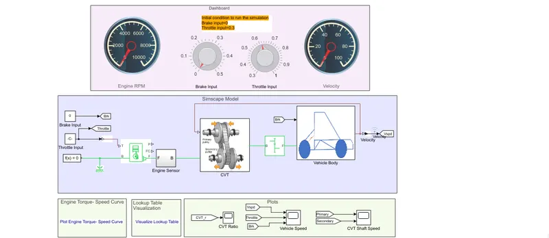
the above arrangement represents dashboard arrangement of vehicle where we can control the throttle input and brake by means of two knobs. the brake input varies from 0 to 0.5 . the throttle input varies from 0.3 to 1. the initial value of throttle input is 0.3 because when we start vehicle rpm will maintain minimum value of 0.3 to not to turn off. in the dashboard we are connecting two guages which represents engine rpm and velocity of vehicle respectively. engine rpm is sensed using the engine sensor and velocity of the vehicle is sensed by using the output of the vehicle body. the brake input is given to the brake shoes and throttle input is given to the generic engine.
we need to adjust the simulation time to inf because we cannot estimate how much time does vehicle runs.
we need to see how the vehicle speed , engine RPM, CVT ratio, primary and secondary shaft speeds are changing when we are adjusting the brake input and throttle input.
let us assume some cases where brake input and throttle inputs are variable.
in a CVT engine there are two pulleys. CVT ratio of the vehicle is defined as ratio of diameter of driven pulley to the driving pulley diameter.
case 1 : throttle input is at 0.3 and brake input is at 0
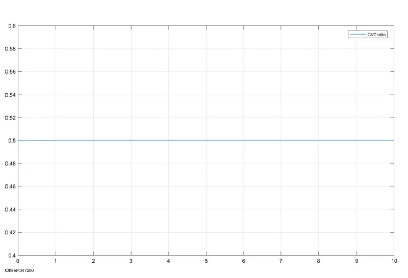
when we run a vehicle by releasing the throttle input and brake input the CVT ratio is maintained to 0.5. this happens because the diameter of the driving pulley is more than driven pulley at low speed moment of vehicle.
let us see the vehicle speed, throttle input and brake input of vehicle
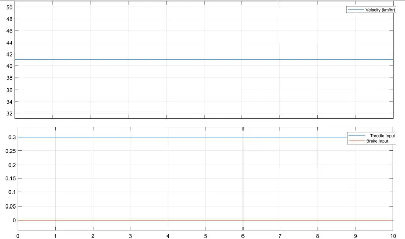
as we can see above that brake input is 0 and throttle input is 0.3 as we adjusted. the vehicle maintains its speed of 41 kmph.
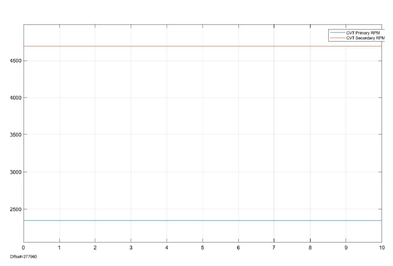
we can also see the rpm of primary shaft and secondary shaft when we maintained low speed.
case 2: when throttle input is high and brake is maintained 0.
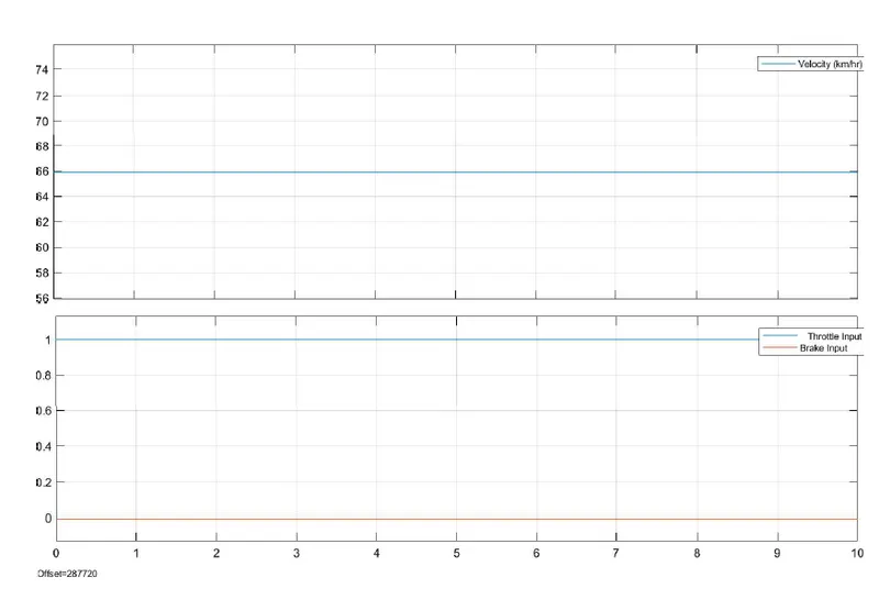
in this case we can see that vehicle speed is maximum because the brake applied is zero and the throttle applied is maximum. the vehicle runs at maximum speed of 66kmph as seen in graph. the applied brake and throttle is also seen in graph.
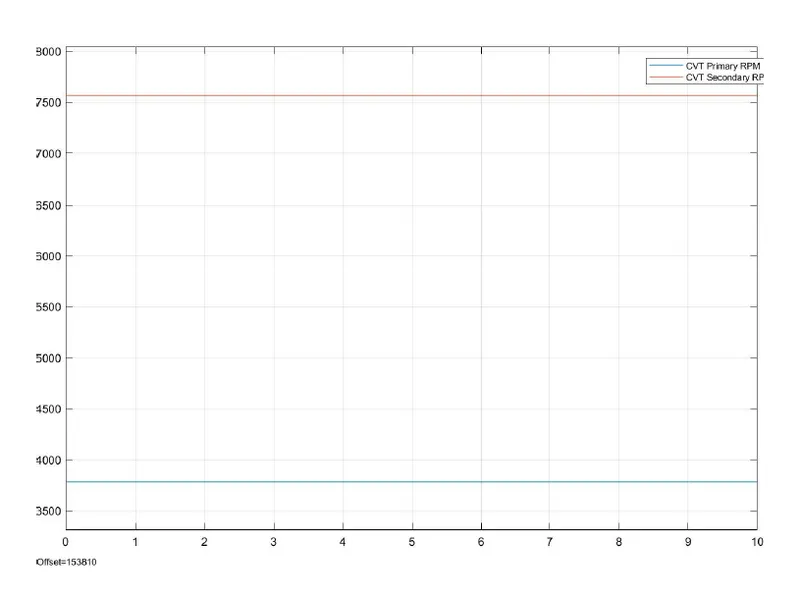
the picture represents the shaft speed of two pulleys. the secondary shaft i.e,, driven shaft rotate at a speed of 7600rpm and the primary shaft i.e,, driving shaft has the speed of 3800rpm. by observing the above phenomenon while the vehicle is acheving high speed the diameter of the driving pulley reduces and the diameter of driven pulley increasing due to this the rpm varies according to the speed.
in this case also the cvt ratio of the vehicle is maintained 0.5.
case 3 : when the brake input is high and the throttle input is maintained 0.3.
in this case the vehicle runs at very low speed because the throttle is maintained low and high brake input. as we can see in the below graph how the velocity, throttle and brake values are changed.
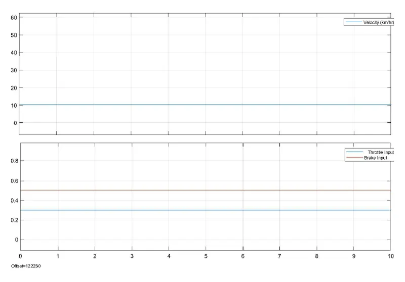
as we can see that the speed of the vehicle is less than 15kmph and the throttle is 0.3 and the brake input is 0.5.
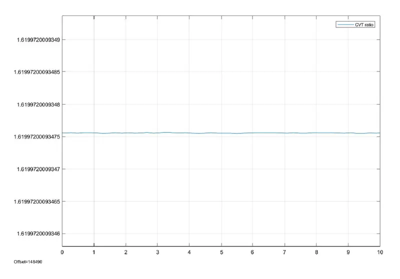
as we can see that the cvt ratio of the vehicle is 1.6 because as the vehicle moves in very low speed the diameter of the driving pulley is higher than the driven pulley.
case4 : when both the inputs are high i.e,, throttle and brake is high.
in this case when the applied throttle is high the vehicle is not going to reach a maximum speed because the brake is applied at its peak.
the velocity of the vehicle is graphed as
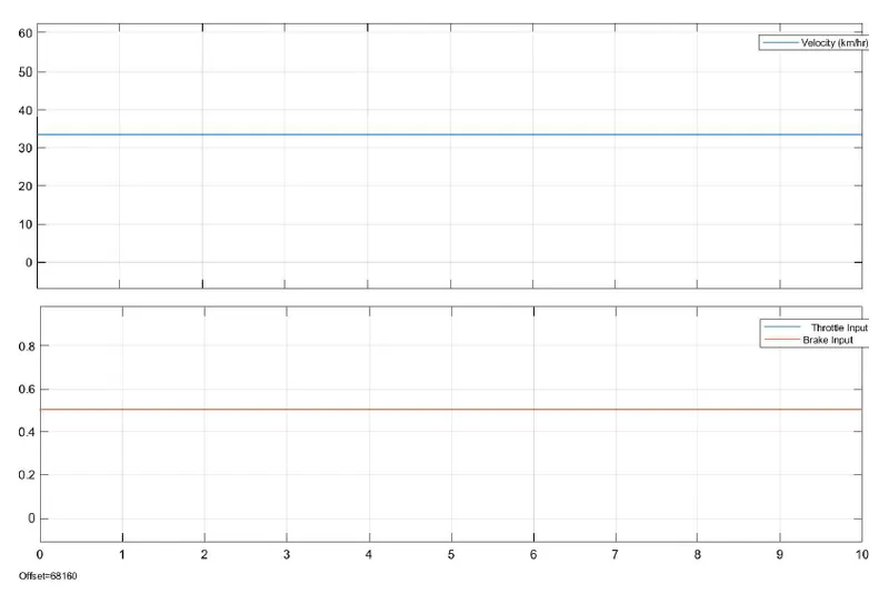
as we can see that the velocity of the vehicle is 33kmph because the applied throttle is maximum but also the applied brake is maximum.
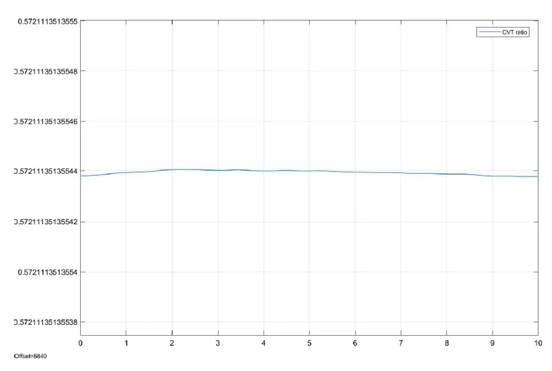
here the cvt ratio slightly fluctuates at 0.5 because the primary shaft and the secondary shaft speed vibrates because of increase in both the inputs.
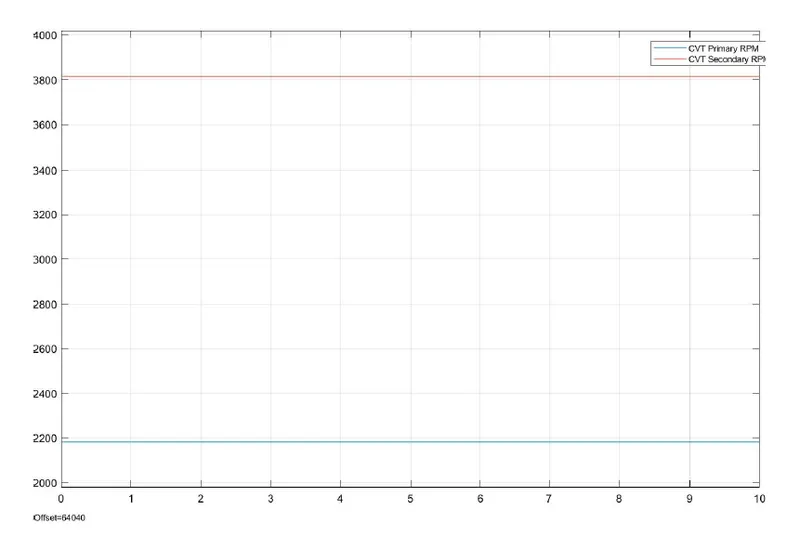
as we see that the primary shaft speed is at 2190rpm and secondary shaft speed is at 3800rpm. as applied brake and throttle the vehicle speed maintains 33kmph at this time the primary pulley has more diameter and the secondary shaft has less diameter. due to this phenomenon the rpm of primary is less than rpm of secondary shaft.