Project
A system-level simulation of an all-terrain vehicle
An All terrain vehicle (ATV) is also known as light utility vehicle. ATV is a vehicle that travels on low pressure tire with seat that is straddled by the operator with handle for steering control.
CASES:-
- Study the baja ATV model without Dashboard.
-
Study the baja ATV model with Dashboard.
-
Study the baja ATV model using lookup table without Dashboard.
-
Study the baja ATV model using lookup table with Dashboard.
Study the baja ATV model without Dashboard.
The major components are used in the ATV model are shown is picture below;
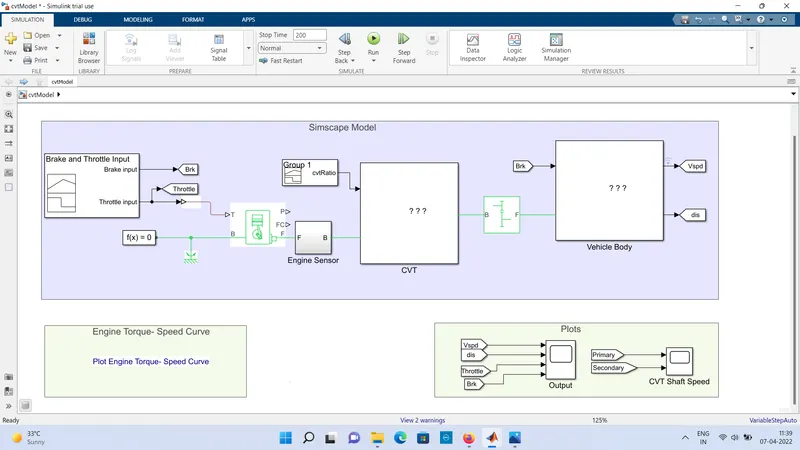
- Input (Brake and Throttle)
- Generic Engine
- Engine sensor
- CVT
- Simple gear
- Vehicle Body
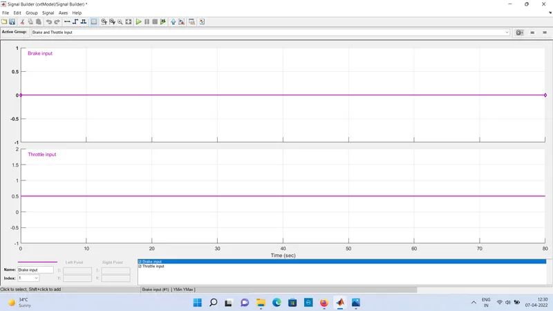
INPUT (BRAKE AND THROTTLE):- The brake and throttle are provide in the form of signal by using the signal builder block. the signals are shown in the picture-
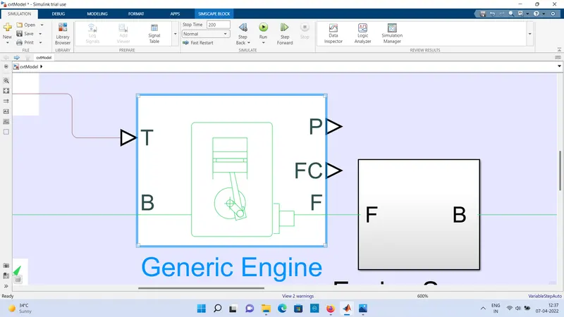
GENERIC ENGINE:- This block is used to represent the system level model of spark iginition is used for initial stage of modelling, in this block their is T and B are input and P FC and F are output. this block is shown in picture
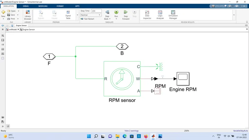
ENGINE SENSOR:- Engine block is made in the subsystem of model
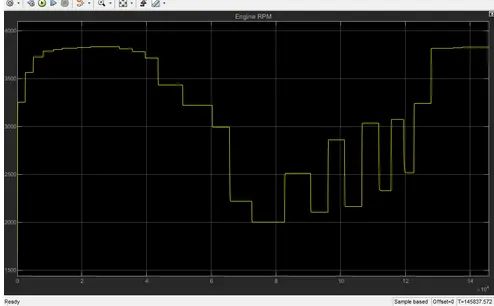
In this model their is RPM sensor which is (Ideal Rotational Motion Sensor) and connect PS terminator and PS simulink converter with scope. that is also shown in picture.
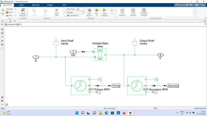
CVT (continously variable transmission ):- A continously variable transmission is an automatic transmission that can change seamlessly through a continous range of gear ratios. this contrasts with other transmissions that provide a limited number of gear ratios in fixed steps. the flexibility of a CVT with suitable control allow the engine to operate at constant RPM while the vehicle moves at varying speed.
A CVT is make in subsystem of model, in this block their are two Ideal Rotational Motion Sensor as CVT PRIMARY RPM AND CVT SECONDARY RPM. where CVT primary RPM is connected to input shaft inertia and CVT secondary RPM is connected to ourput shaft inertia, where as the variable Ratio Gear is connected in the center of both input and output inertia, where B is input and F is output.
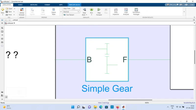
SIMPLE GEAR:- The simple gear block is used after the CVT . Gear is a rotating circular machine part having cut teeth. In gearwheel inserted teeth mesh with another tooth part to transmit torque and speed. in this block their is B is input and F is output.
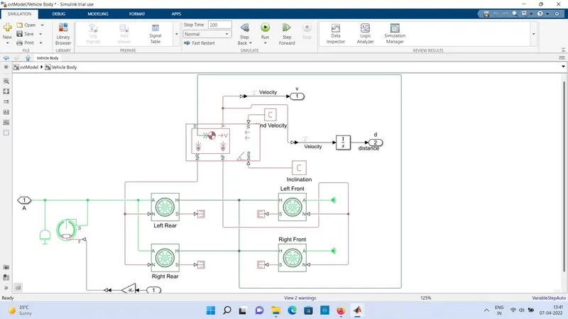
VEHICLE BODY:- The main part is vehicle body and 4 tires which is left rear, right rear, left front and right front, Double brake shoes and inertia. all this blocks are shown in picture below .
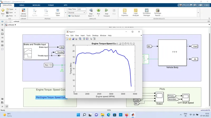
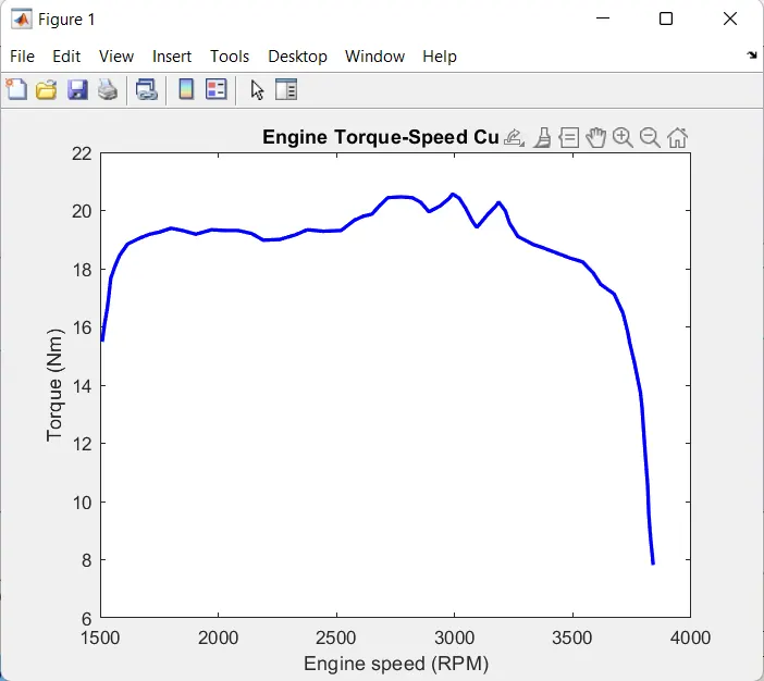
Engine speed - torque curve:- show engine speed torque curve in picture below with regular input in brake and throttle.
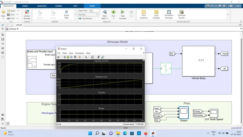
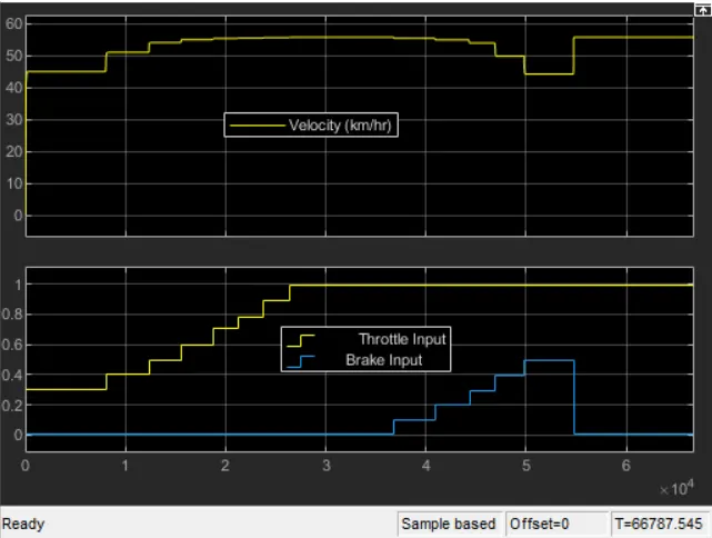
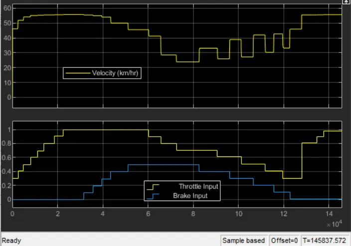
OUTPUT IN SCOPE OF VEHICLE BODY AND THROTTLE:- output of body and throttle input is shown in scope of output.
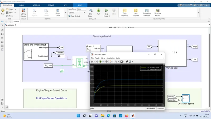
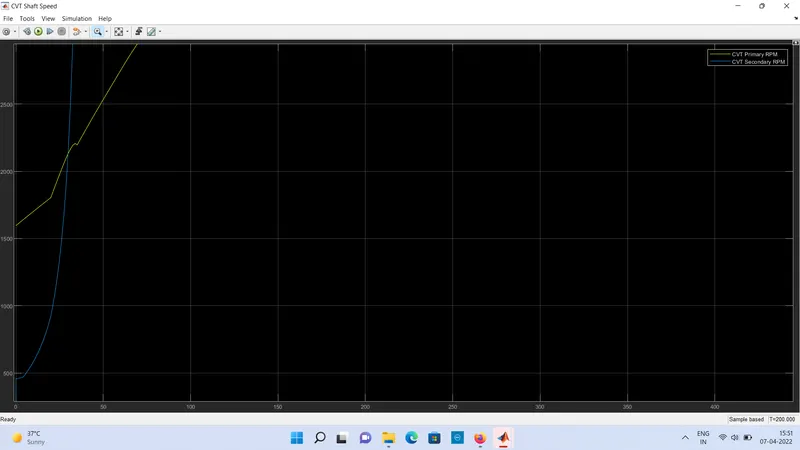
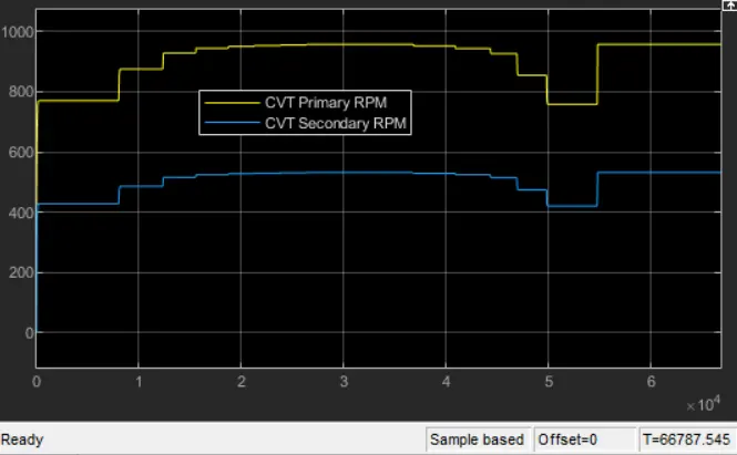
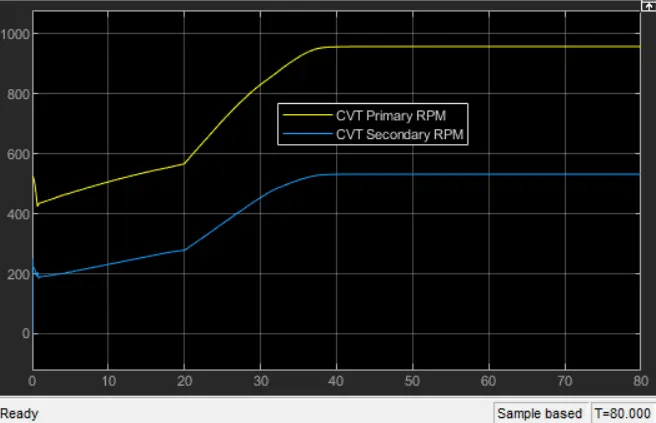
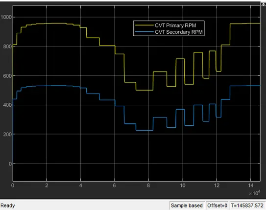
CVT SHAFT SPEED IN SCOPE:- CVT Shaft speed is shown in scope of primary and secondary CVT .
Study the baja ATV model with Dashboard.
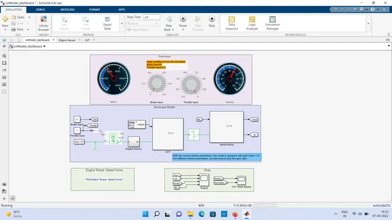
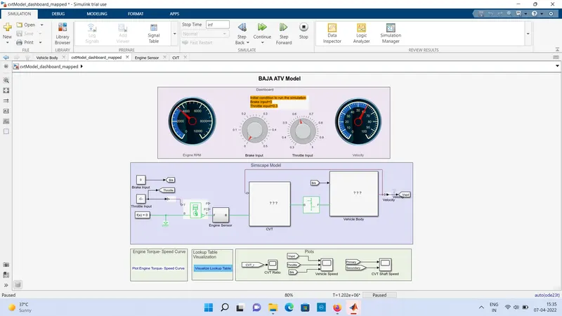
The figure below show Baja with dashboard model which consist throttle mater abd break input in the dashboard which give input through signal builder. The main concept of using using dashboard is study the result by varying the input of brake and throttle, which show the velocity and speed of engine. The gear ratio is mqaintained 2.3 for 5secs and linearly decrease to 1.8 and maintained constant for overall simulation. The brake input varies from 0-0.5n the velocity and speed decrease accordingly by increasing the throttle , the velocity and speed of the engine and shaft increase.
Study the baja ATV model using lookup table without Dashboard.
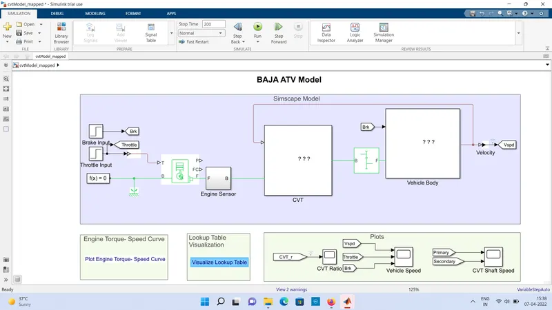
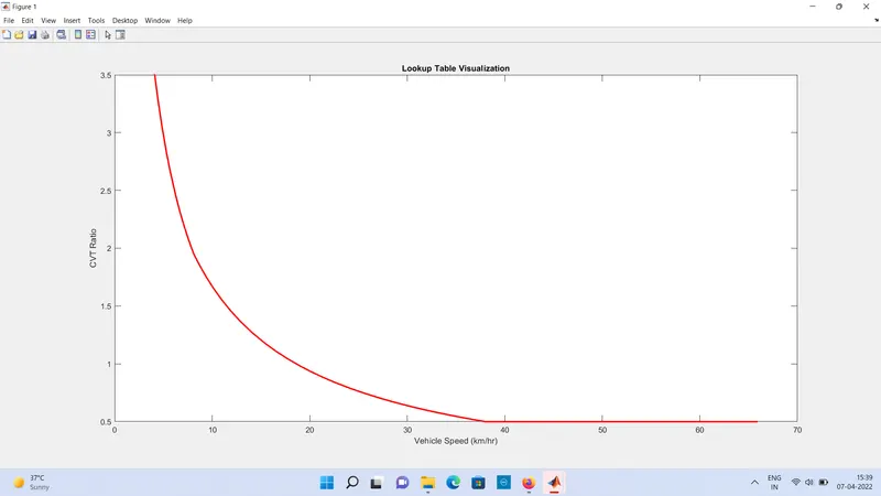
Lookup Table visualization
Study the baja ATV model using lookup table with Dashboard.
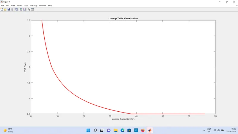
Lookup Table
OUTPUT:-
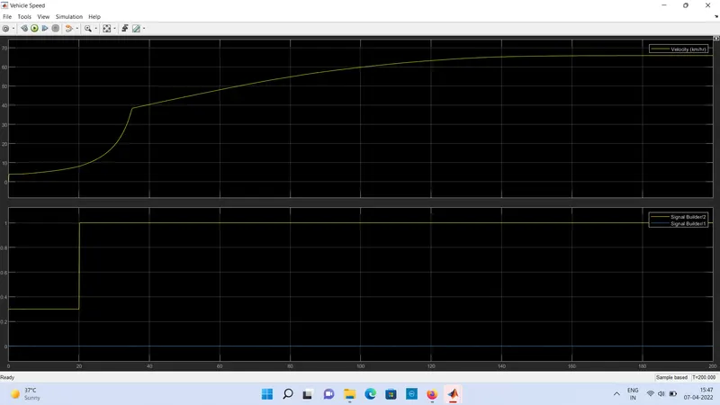
Study 1- Variation of velocity and shaft speed
 .
.
Study 2- Variation of velocity and shaft speed
Study 3- Variation of velocity and shaft speed
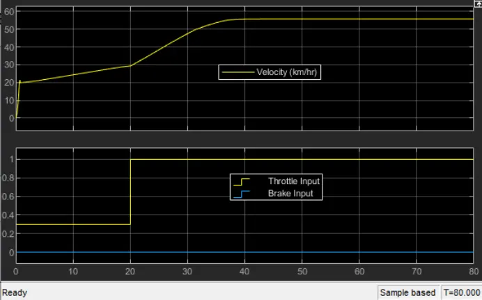
Study 4- Variation of velocity and shaft speed
CONCLUSION:-
As the throttle increase, the velocity is also increase which in turn the power in the engine also increase.

in the begining the speed reducing because of gear ratio and torque output, when the gear ratio increase torque also increase.
2. The brake input increase , the velocity decrease and engine power also decrease. the brake input value engine shutdown and there is no power output. the engine power is inversly proportional to brake input.
3. The gear ratio increase torque incease which in turn the velocity decrease.
4. With the help of lookup table, we can varies any input value and also get the output value by using interpolation and extrapolation method which the simulink can solve..