Project
OBJECTIVE : To carry out a system-level simulation of an all-terrain vehicle.
An all-terrain vehicle (ATV) is defined as a motorized off-highway vehicle designed to travel on four low-pressure or non-pneumatic tires, having a seat designed to be straddled by the operator and handlebars for steering control.
Continuously variable transmission (CVT) is an automatic transmission that can change seamlessly through a continuous range of gear ratios. This contrasts with other transmissions that provide a limited number of gear ratios in fixed steps. The flexibility of a CVT with suitable control may allow the engine to operate at a constant RPM while the vehicle moves at varying speeds. The most common type of CVT uses two pulleyes connected by a belt or chain; however, several other designs have also been used at times.
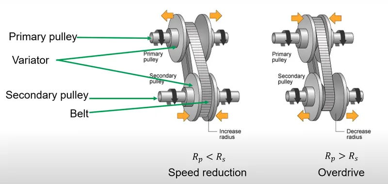
If variator of primary pulley goes outward and secondary pulley goes inward then it will lead to speed reduction.
If variator of primary pulley goes inward and secondary pulley goes outward then it will lead to overdrive as shown in image above.
Main components of BAJA ATV :
Vehicle body
Suspension
Tires
Engine
CVT
1.1. Simulink model for BAJA ATV WITH CVT
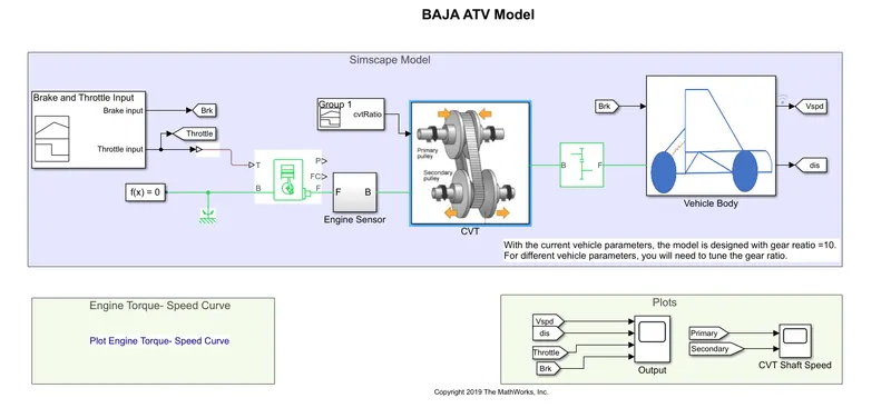
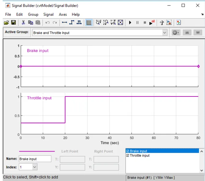
Signal Builder is used to provide input values of brakes and throttle and is connected with Generic engine block.
brake input =0
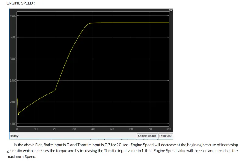
throttle input =0.3 for firts 20 sec, after that input becomes 1.
Generic Engine:
Represents a system-level model of spark-ignition and diesel engines suitable for use at initial stages of modeling when only the basic parameters are available. Optional idle speed and red line controllers are included.
The throttle input signal T lies between zero and one and specifies the torque demanded from the engine as a fraction of the maximum possible torque. If the engine speed falls below the Stall speed, the engine torque is blended to zero. If the engine speed exceeds the Maximum speed, the simulation stops and issues an error message.
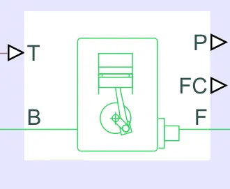
Connections F and B are mechanical rotational conserving ports associated with the engine crankshaft and engine block, respectively. Connections P and FC are physical signal output ports through which engine power and fuel consumption rate are reported.
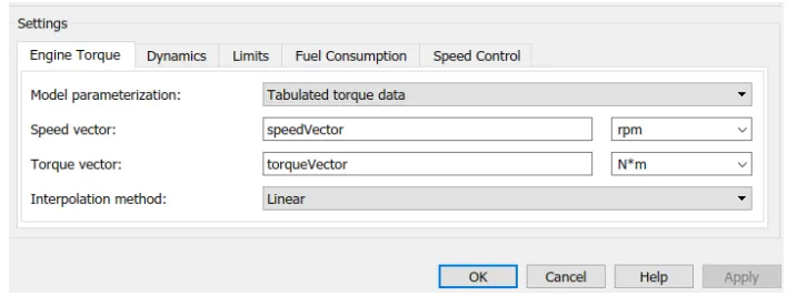
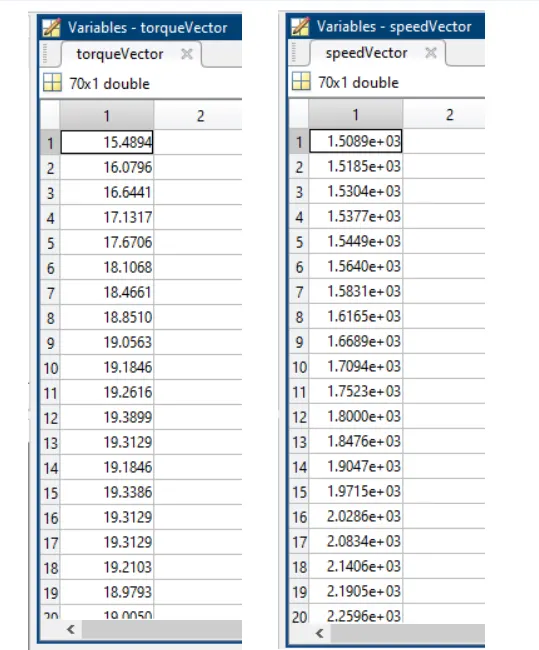
TorqueVector and SpeedVector value is already assigned in the MATLAB program in an array data set.
Engine Sensor: It is connected with the generic engine and contains ideal mechanical rotational sensor that convers and across variable mesured between two mechanical rotational nodes into a control proportional angular velocity or angle.
Simple gear: Engine is connecting to CVT with simple gear ratio for speed reduction.
CVT Ratio :It is connected with CVT by providing random ratio values of velocity for those random CVT ratio.
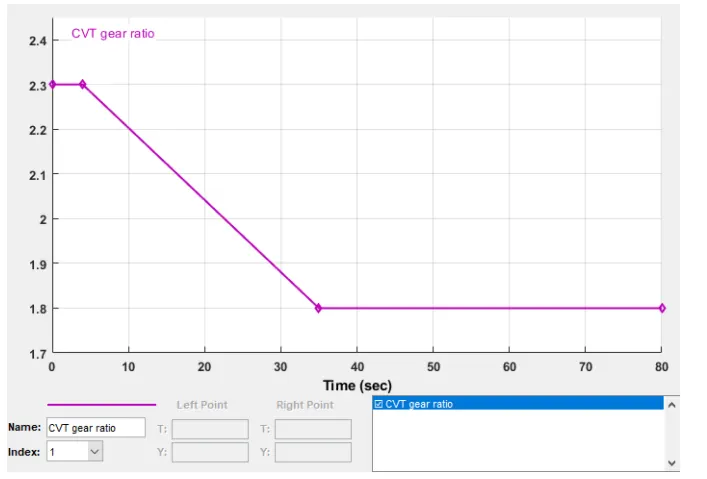
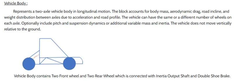
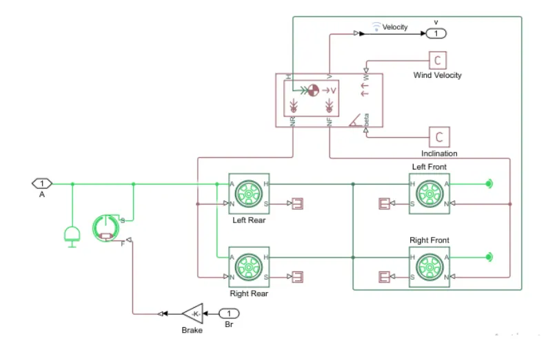
Figure of vehicle body
1.2. Simulink model for BAJA ATV with CVT using dashboard
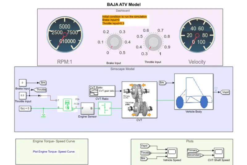
In the above simulink model , RPM(Speed) guage, Break input guage, Throttle input guage and velocity input guage is connected in dashboard. Brake input =0; throttle input =0.3 at initial stage.
With the help of dashboard variation of speed and velocity will be observed in RPM and Velocity guage while running simulation.
RPM reffers to the speed of primary and secondary pulley and velocity defines the speed of vehicle.
2.1. Simulink model for BAJA ATV with CVT using lookup table
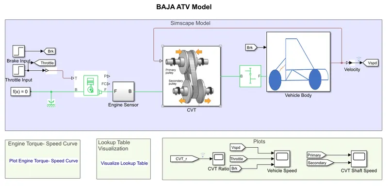
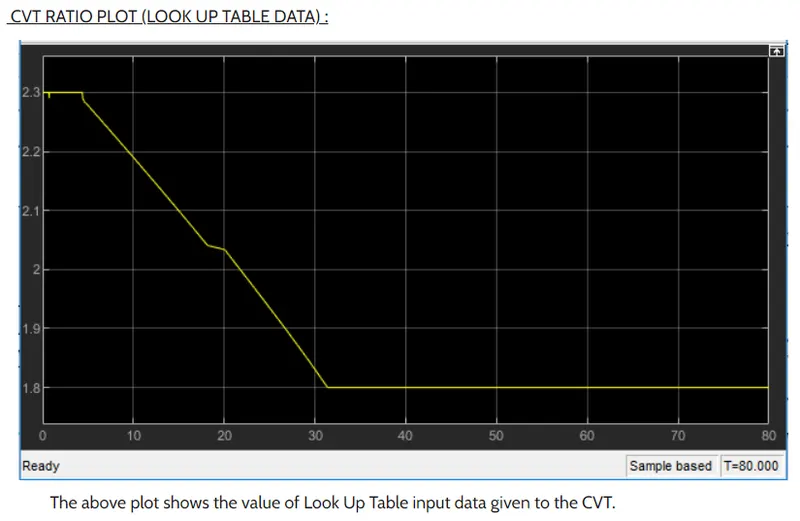
Lookup table data has beed assigned as input to the CVT instead of giving CVT ratio.
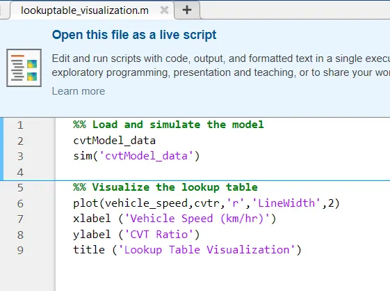
Workspace: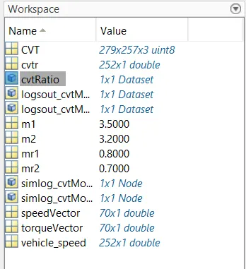
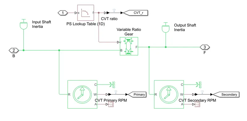
Input provided via lookup table in given sub system
2.2. Simulink model for BAJA ATV with CVT using dashboard with lookup table
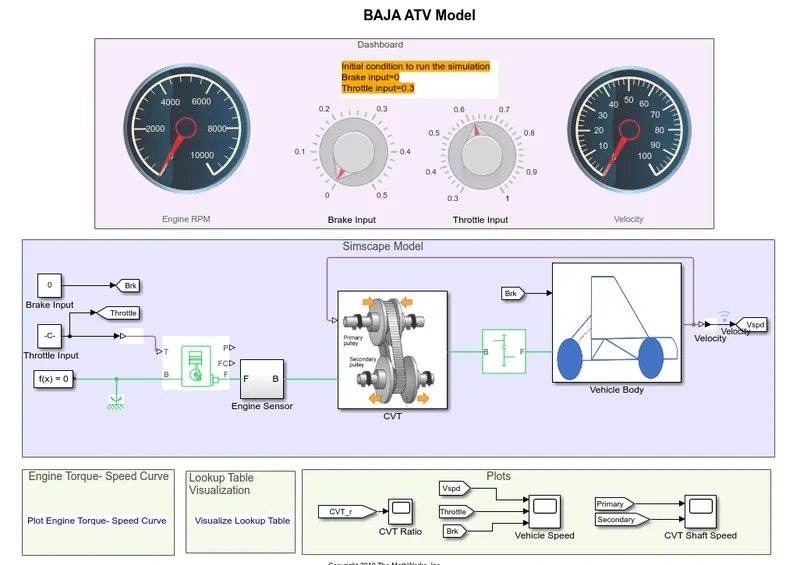
In the above simulink model , RPM(Speed) guage, Break input guage, Throttle input guage and velocity input guage is connected in dashboard. Brake input =0; throttle input =0.3 at initial stage.
Lookup table data has beed assigned as input to the CVT instead of giving CVT ratio.
Results
1.1. Simulink model for BAJA ATV WITH CVT
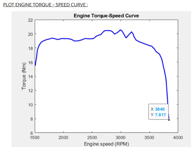
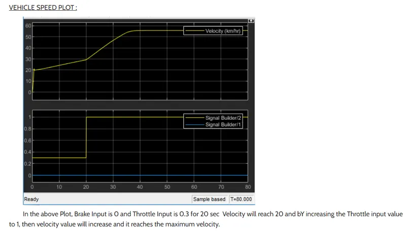
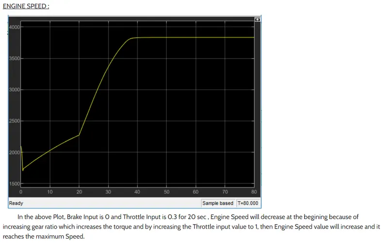
In the above plot the max torque reaches 3840 RPM and vehicle speed depends on CVT ratio.
CVT shaft Speed Plot:
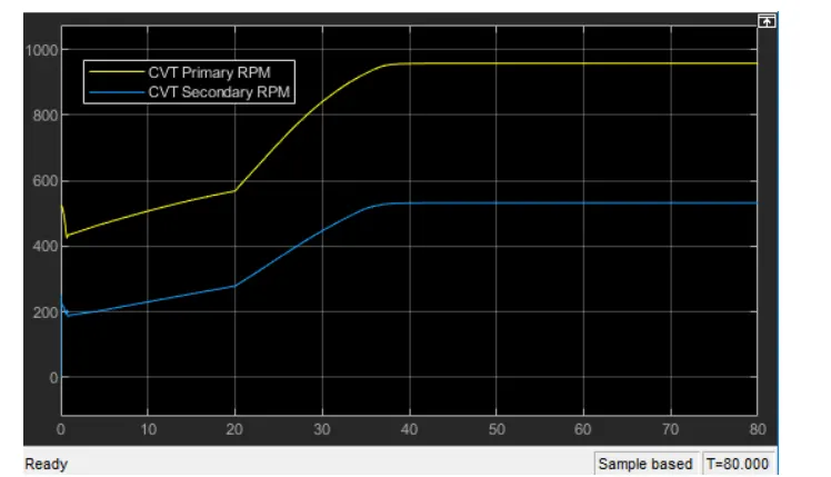
In CVT variator of primary pulley goes inward and secondary pulley goes outward it will lead to overdrive.Primary pulley radius increases and secondary pulley radius decreases so speed of primary pulley is greater than secondary pulley.
Rp>Rs
1.2. Simulink model for BAJA ATV with CVT using dashboard
Initial stage both RPM and Velocity guage shows zero in display.
Giving time value as infinite in simulation we provide manual input to throttle and observe variation of RPM as well as velocity.
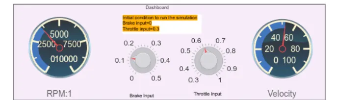
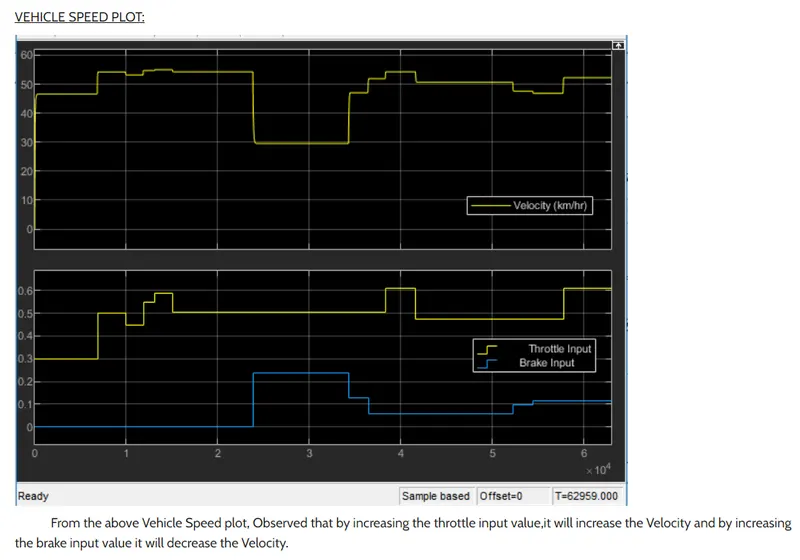
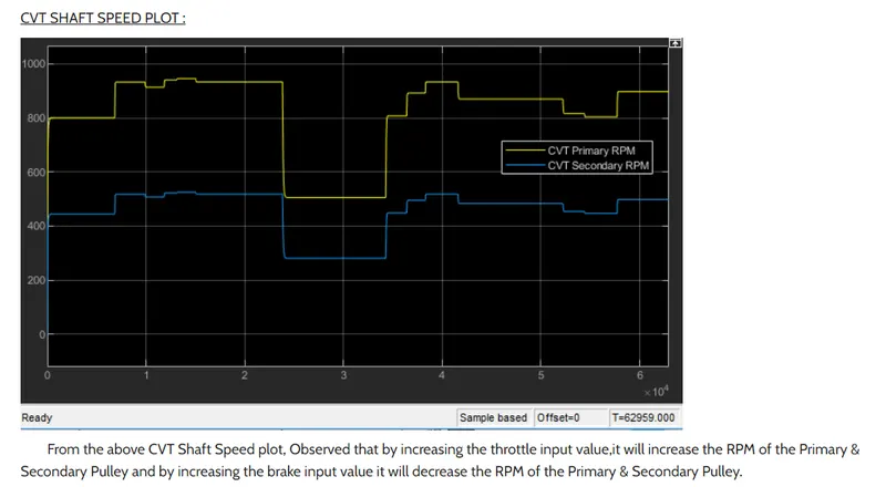
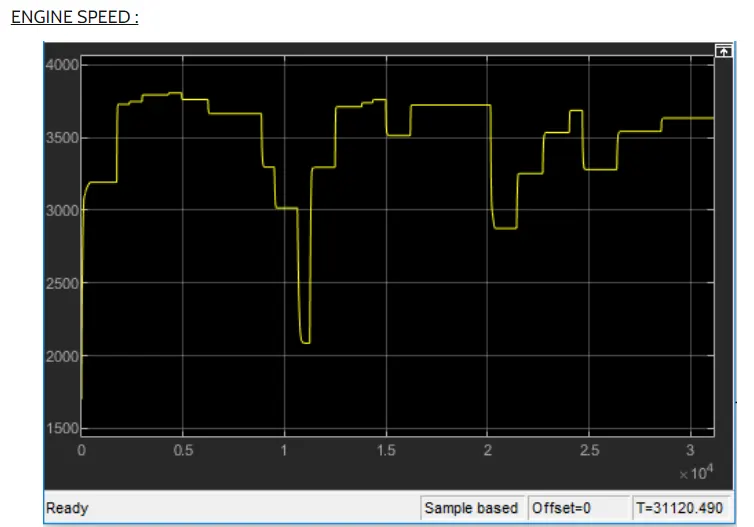
From above plot we observe that increasing the throttle input value will increase the engine speed and by increasing the brake input value will decrease the engine speed.
2.1. Simulink model for BAJA ATV with CVT using (lookup table)
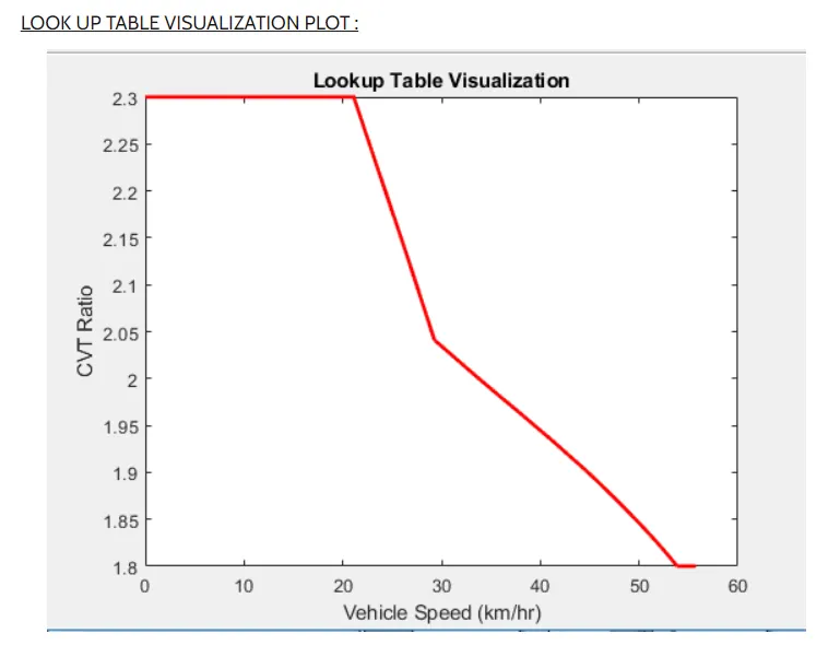
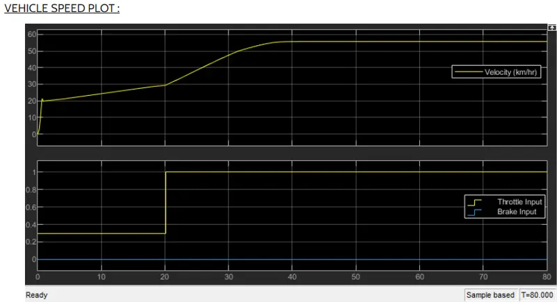
In the above plot the brake input 0, throttle input to 0.3 for 20 sec then to 1, velocity value will increase and reach the maximum velocity.
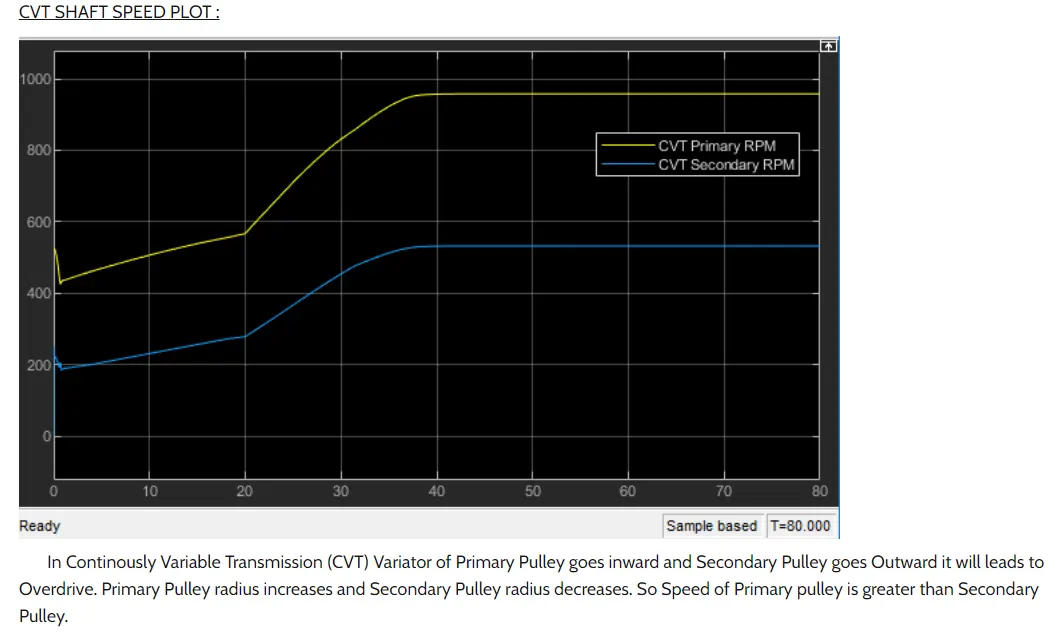
Rp>Rs
2.2. Simulink model for BAJA ATV with CVT using dashboard with lookup table
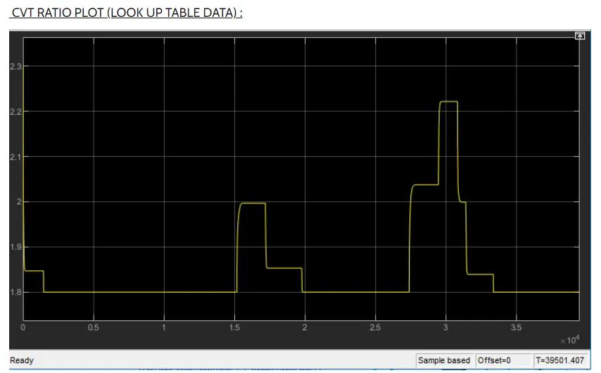
In the above plot the CVT will vary by changing the throttle guage. Throttle value increases CVT ratio decreases and vis a vis.
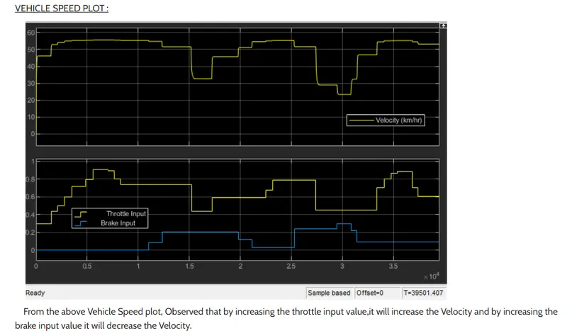
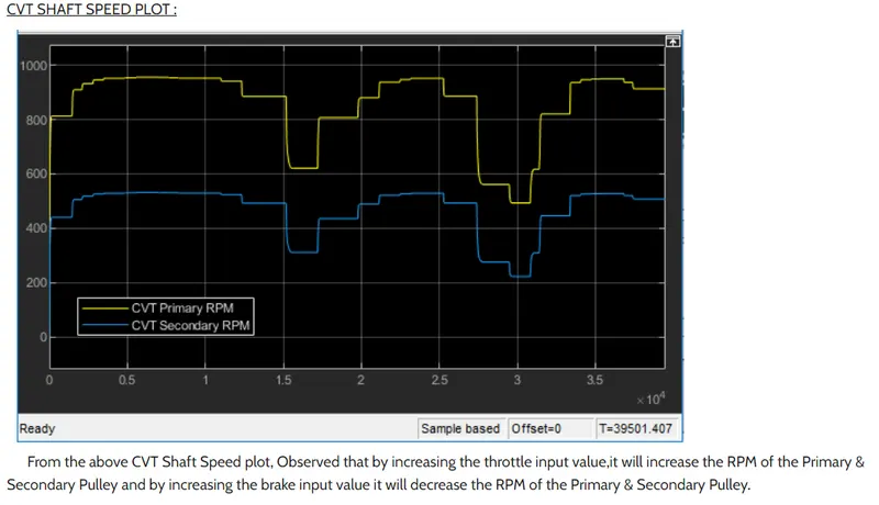
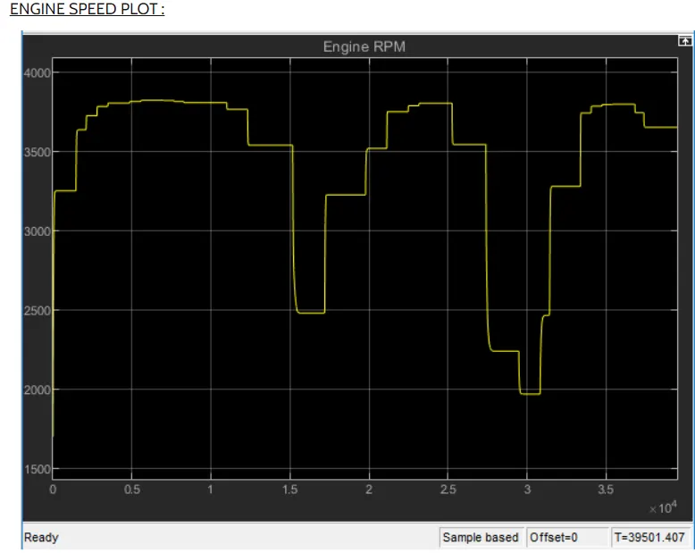
From above plot we observe that by increasing the throttle input , it will increase the engine speed and by increasing the break input value it will decrease the engine speed.
Conclusion:
System level simulation of a BAJA ATV with and without using lookup table has been caried out and technical report has ben prepared and output results are plotted.