Project
Aim: To carry out a system-level simulation of a BAJA ATV
Objectives:
- Analyse all components and understand the relation and flow between the blocks
Understand the different types of ways to model this BAJA ATV
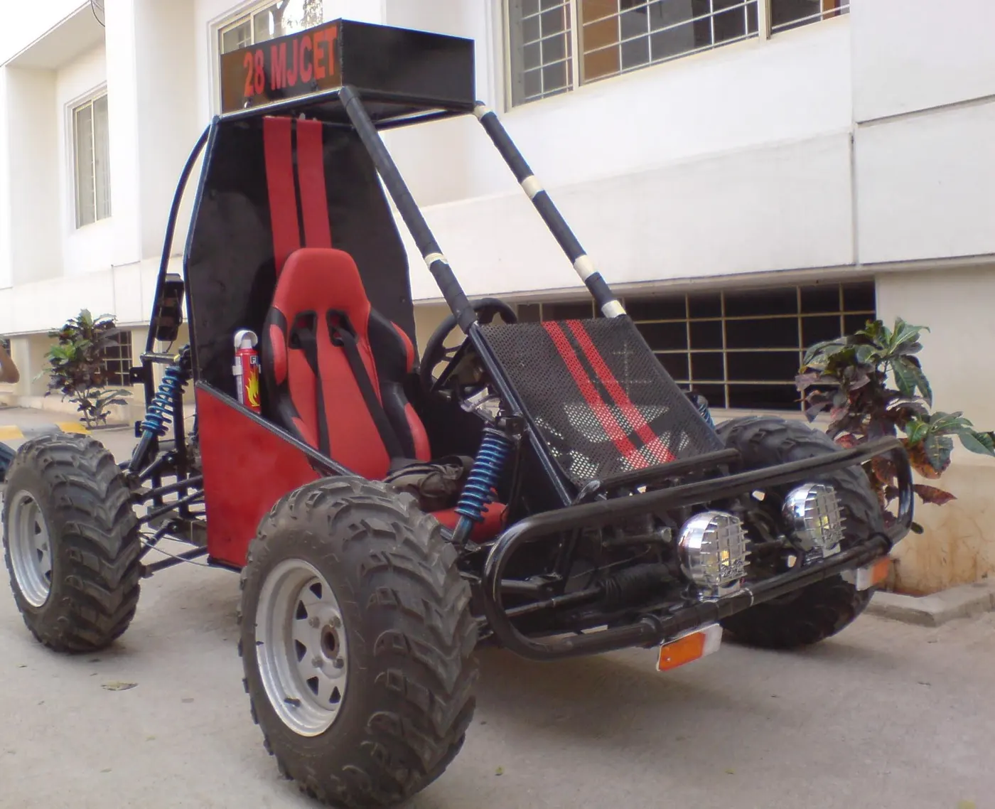
- An ATV is a small motor vehicle with three or four low-pressure tires designed for use on various types of terrain. Recreational acitivities in deserts are usually carried out in ATVs. This project is in reference to one of the types of ATVs used in BAJA SAE competitions.
ATV:
An all-terrain vehicle (ATV), also known as a quad (bike), three-wheeler, four-track, four-wheeler, or quadricycle, as defined by the ANSI is a vehicle that travels on low-pressure tires, with a seat that is straddled by the operator, along with handlebars for steering control. As the name implies, it is designed to handle a wider variety of terrain than most other vehicles.
Simulink Model:
CVT:
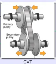
A continuously variable transmission (CVT), also known as a shiftless transmission, stepless transmission, pulley transmission, or, in case of motorcycles, a 'twist-and-go', is an automatic transmisson that can change seamlessly through a continuous range of effective gear ratios. This contrasts with other mechanical transmissions that offer a fixed number of gear ratios. The flexibility of a CVT with suitable control may allow the input shaft to maintain a constant angular velocity even as the output speed varies.
CVT Subsystem block:
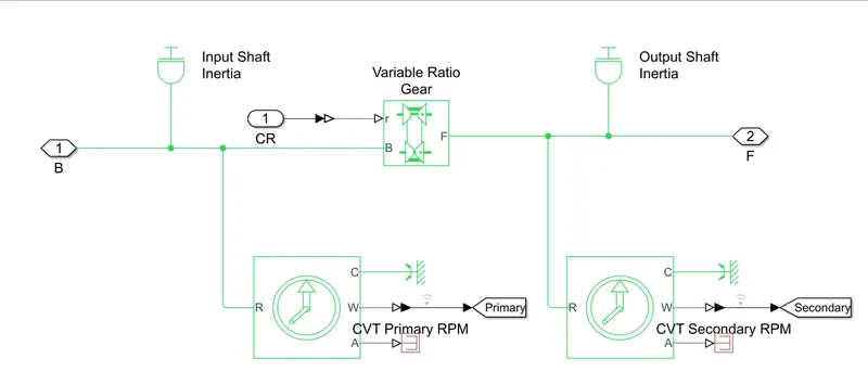
- The input and output shaft inertia represent primary pulley (driver) and secondary pulley (driven), respectively.
- The variable ratio gear block represents the multiple gears of the CVT, with the gear ratio input given to Port R (shown below)
- Two rotational motion sensors are for tracking the angular velocities of the two pulleys.
Input shaft represents the primary pulley and output shaft represents the secondary pulley and mechanical rotational sensor is connected to input and output shafts and Variable ratio Gear represents a variable ratio gearbox such as implemented by mechanical belt CVT, electric, or hydraulic transmissions. The physical signal input r defines the ratio of input to output angular shaft velocities.Connections B (base) and F (follower) are mechanical rotational conserving ports. Specify the relation between base and follower rotation directions with the Output shaft rotates parameter.
Vehicle body subsystem block:
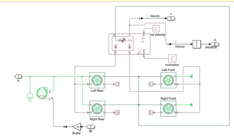
- The Vehicle Body accounts for body mass, aerodynamic drag, road incline, and weight distribution between axles due to acceleration and road profile.
- The Double-Shoe Brake is to apply brakes to the rear wheels. With this component, two brake blocks are applied at opposite ends of the drum. This prevents an unbalanced force from acting on the shaft and bearing connecting the drum to the wheel, which would be the the case with a single-shoe brake.
- All of the above is applied to the four wheels
This block represents the longitudinal behavior of a highway tire characterized by the tire Magic Formula. The block is built from Tier-Road Interaction and Simscape Foundation Library wheel and Axle blocks. The effects of tire inertia, stiffness, and damping can be included.
Connection A is the mechanical rotational conserving port for the wheel axle.
Connection H is the mechanical translational conserving port for the wheel hub through which the trust developed by the tire is applied to the vehicle.
Connection N is a physical signal input port that applies the normal force acting on the tire. The force is considered positive if it acts downwards.
Connection S is a physical signal output port that reports the tire slip.
Connection M is optionally exposed physical signal ports set to parameterize by physical signal Magic Formula coefficients.
Connection W is the wind velocity.
Double-Shoe Brake:
This block represents a brake arranged as two pivoted rigid shoes symmetrically installed inside or outside a drum and operated by one actuator. The actuator force causes the shoes to exert a friction torque on a shaft connected to the drum.
Connection S is a conserving rotational terminal associated with the drum shaft.
Connection F is a physical signal port representing the force input to the actuator. Positive force creates friction torque that resists shaft rotation.
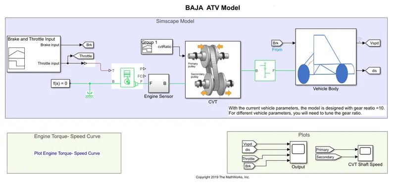
The output inertia shaft motion generated by the gearbox will be transmitted to the wheel axles of the front and rear. simulation is done to measure the vehicle velocity and distance the vehicle traveled. From tags are connected to output block where the data is received from Goto tags v and d connected in-vehicle body subsystem. Constant blocks C are connected one for the inclination and the other for wind velocity.
Generic engine:
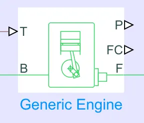
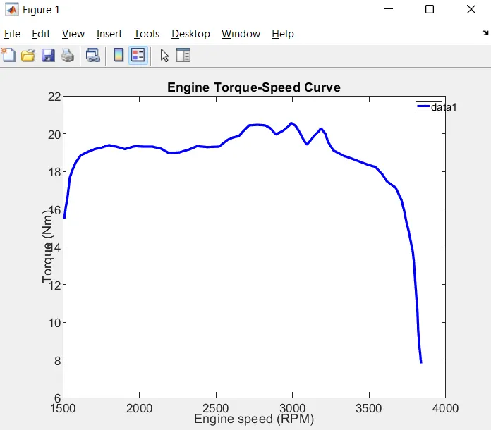
- The engine uses a programmed relationship between speed and torque, modulated by the throttle signal. The throttle input is seen above (fed into port T) and the speed-torque data points are extracted from the graph shown below and fed into the engine through creation of column vectors in MATLAB.
- Crankshaft (Port F) is connected to an engine sensor, which simply senses the angular velocity and angular displacement of the crankshaft.
- The simple gear between engine and the CVT gear box is to slow down the engine RPM (in case it is too high) before it is fed to the CVT. An appropriate gear ratio needs to be selected so that over or under-revving isn't an issue.
Brake and throttle input signal:
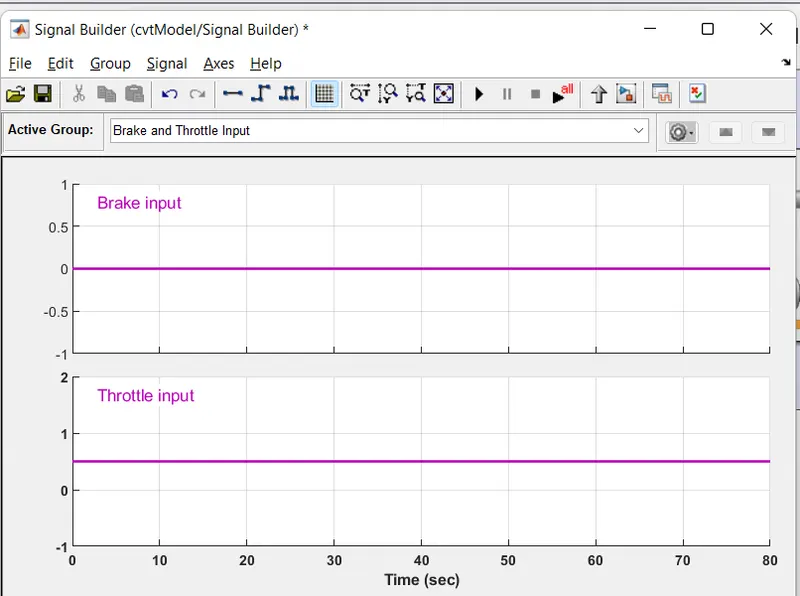
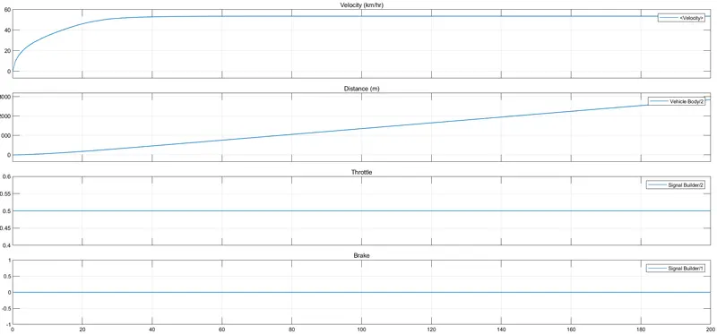
No brake is provided
A constant throttle of 0.5 for the first 80 seconds.
These two parameters are fed into the engine.
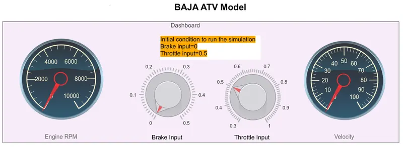
Dashboard: A dashboard (also called dash, instrument panel (IP), or fascia) is a control panel usually located directly ahead of a vehicle's driver, displaying instrumentation and controls for the vehicle's operation.
In this model, a dashboard is provided with two custom gauges from the simscape library by drag and drop option, one for visual display of RPM and the other for velocity where we input data manually. Similarly, we drag and drop Knob blocks from the library for brake input and throttle input. Instead of Signal builder, we connect constant blocks to input brake value and throttle value.
The initial conditions are as follows:
Brake Input = 0
Throttle Input = 0.5
Output:
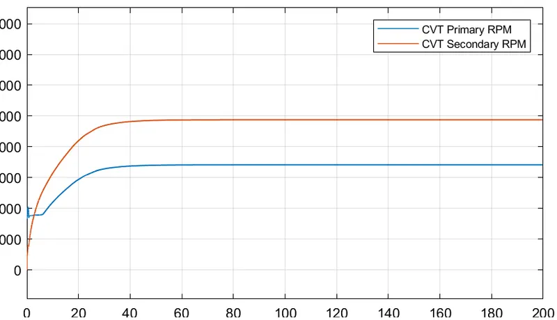
CVT shaft speed:
CONCLUSION: Hence, the given BAJA ATV Model was simulated successfully and from the above results, we can infer that:
- Velocity, CVT Shaft Speed and Engine Speed are directly proportional to the Throttle input and inversely proportional to the Brake input.
- CVT Ratio is directly proportional to Torque and inversely proportional to the Throttle input.
- CVT Primary speed is greater than CVT Secondary speed as they are directly proportional to their shaft diameter.
- The speed might get null at a particular braking resistance.