Project
Aim :- To perform the simulation of the BAJA All-Terrain vehicle (ATV) model and observe the CVT shaft speed and vehicle speed output graph by changing brake and throttle inputs.
Solution:-
Theory:-
An all-terrain vehicle (ATV), also known as a light utility vehicle (LUV)An all-terrain vehicle (ATV), also known as a light utility vehicle (LUV). ATVs are three-wheeler, four-track, four-wheeler, or quadricycle, as defined by the American National Standards Institute (ANSI) is a vehicle that travels on low-pressure tires, with a seat that is straddled by the operator. along with the handlebars for steering control. As the name implies, it is designed to handle a wider variety of terrain than most other vehicles.
By the current ANSI definition, ATVs are actually intended for use by a single operator, although some companies have
developed ATVs intended for use by the operator and one passenger. These ATVs are referred to as tandem ATVs.
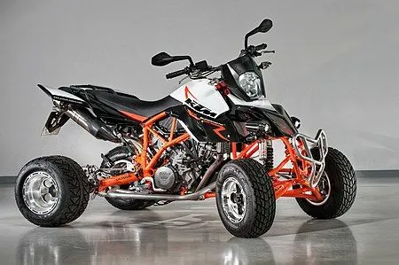
Major and Crucial Components:
1.CVT
2.Vehicle Body
3.Generic Engine
4.Simple Gear
5.Tires and Brakes
1) Continuously variable transmission (CVT)
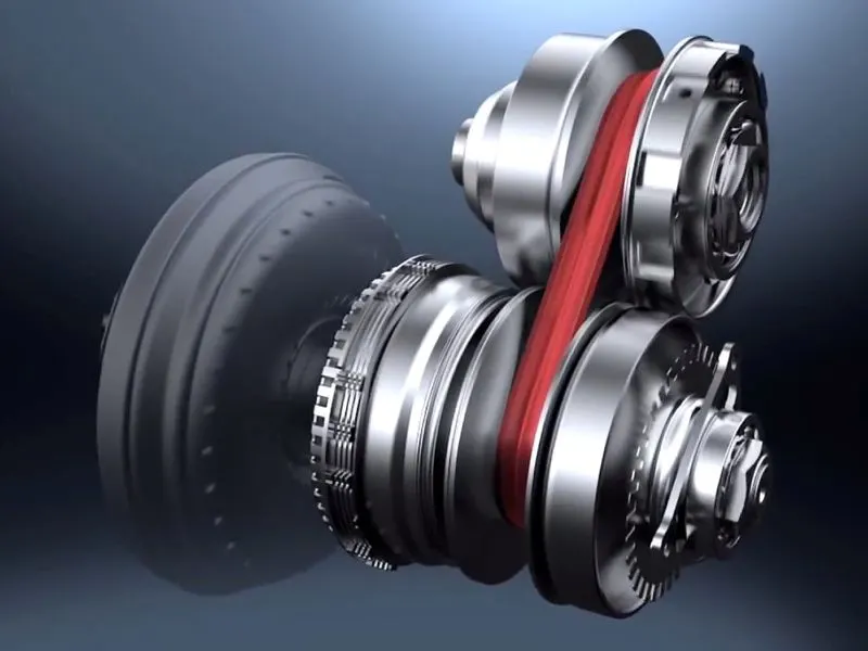
A continuously variable transmission (CVT) is an automatic transmission that can change seamlessly through a
continuous range of gear ratios.This contrasts with other transmissions that provide a limited number of gear ratios in
fixed steps. The flexibility of a CVT with suitable control may allow the engine to operate at a constant RPM while the
vehicle moves at varying speeds
The most common type of CVT uses a V-belt which runs between two variable-diameter pulleys. The pulleys consist of two cone-shaped halves that move together and apart. The V-belt runs between these two halves, so the effective diameter of the pulley is dependent on the distance between the two halves of the pulley. The V-shaped cross-section of the belt causes it to ride higher on one pulley and lower on the other; therefore, the gear ratio is adjusted by moving the two sheaves of one pulley closer together and the two sheaves of the other pulley farther apart.
As the distance between the pulleys and the length of the belt does not change, both pulleys must be adjusted (one bigger, the other smaller) simultaneously in order to maintain the proper amount of tension on the belt. Simple CVTs combining a centrifugal drive pulley with a spring-loaded driven pulley often use belt tension to effect the conforming adjustments in the driven pulley. The V-belt needs to be very stiff in the pulley's axial direction in order to make only short radial movements while sliding in and out of the pulleys.
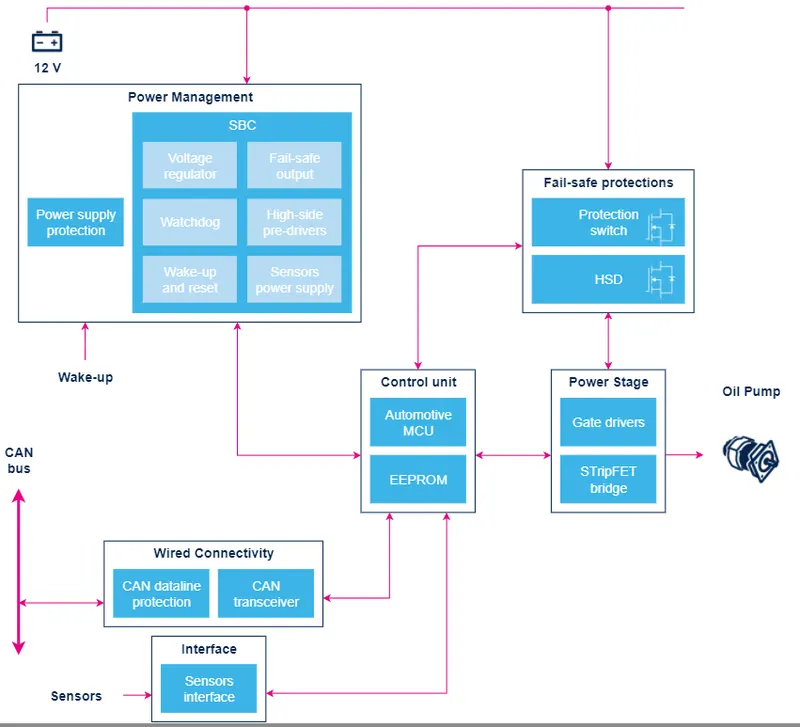
2) Vehicle Body
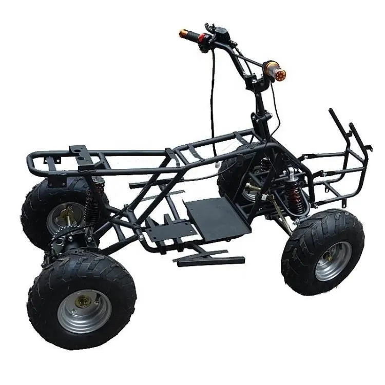
A Baja ATV vehicle of a Two-axle type vehicle with longitudinal dynamics and motion has adjustable mass, geometry, and drag properties. The vehicle can have the same or a different number of wheels on each axle. For example,If two wheels on the front axle and one wheel on the rear axle. The vehicle wheels are assumed identical in size. The vehicle can also have a
center of gravity (CG) that is at or below the plane of travel so that it mitigates the chances of rolling over.
3) Generic Engine
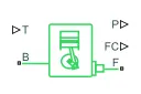
Represents a system-level model of spark-ignition and diesel engines suitable for use at initial stages of modeling when only the basic parameters are available. Optional idle speed and red line controllers are included.
The throttle input signal T lies between zero and one and specifies the torque demanded from the engine as a fraction of the maximum possible torque. If the engine speed falls below the Stall speed, the engine torque is blended to zero. If the engine speed exceeds the Maximum speed, the simulation stops and issues an error message.
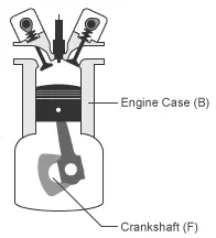
Connections F and B are mechanical rotational conserving ports associated with the engine crankshaft and engine block, respectively. Connections P and FC are physical signal output ports through which engine power and fuel consumption rate are reported.
4) Simple gear
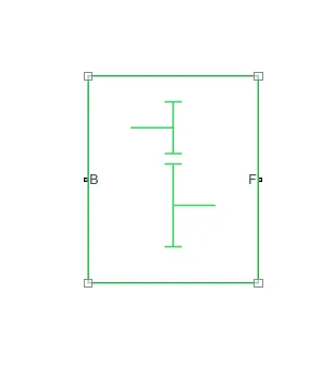
Represents a fixed-ratio gear or gear box. No inertia or compliance is modeled in this block. You can optionally include gear meshing and viscous bearing losses.
Connections B (base) and F (follower) are mechanical rotational conserving ports. Specify the relation between base and follower rotation directions with the Output shaft rotates parameter. Optionally include thermal effects and expose thermal conserving port H by right-clicking on the block and selecting Simscape block choices to switch between variants.
5) Tires and brakes
i) Tire
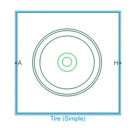
The vehicle body is connected to 4 tires each per axle to move the vehicle according to the power input to the axle.
Where,
N- Normal Force
S-Tire Slip
A- Axle
H-Mechanical translational port associated with the wheel hub that transmits then the thrust generated by the
tire to the remainder of the vehicle
ii) Brake
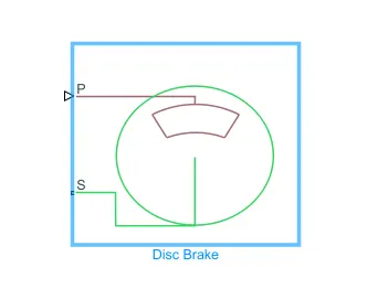
Represents a brake arranged as a cylinder applying pressure to one or more pads that can contact the shaft rotor. Pressure from the cylinder causes the pads to exert friction torque on the shaft.
Connection S is a conserving rotational terminal associated with the shaft. Connection P [bar] is a physical signal port representing the cylinder pressure. Positive pressure creates friction torque that resists shaft rotation. Optionally include thermal effects and expose thermal conserving port H by setting Thermal port to Model.
CVT Simulink modal :-
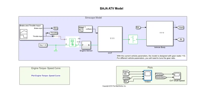
In this model, we have a dashboard that contains knobs to control the Throttle and Brake inputs. In this case, the inputs
are not provided using the signal builder. A constat block is provided to control both the parameters in real-time for the
user. One can vary it as they want and will get the result according to that.
In the Above Simulink Model, RPM(Speed) gauge,Brake Input gauge, Throttle Input gauge and Velocity gauge is
Connected in the dash board. Brake input is O and Throttle input is 0.5 for Initial Condition to run the Simulation.
Dashboard is connected with BAJA All terrain Vechicle using CVT in Simulink Model.With the help of Dashboard, variation
of Speed and Velocity will display in the RPM:1 gauge and Velocity gauge, while running the Simulation. RPM gauge refers
the Speed of the Primary & Secondary Pulley and Velocity gauge refers the Speed of the Vehicle.
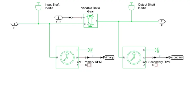
CVT Subsystem:-
Output :-
1) Plot of Engine of torque-speed curve
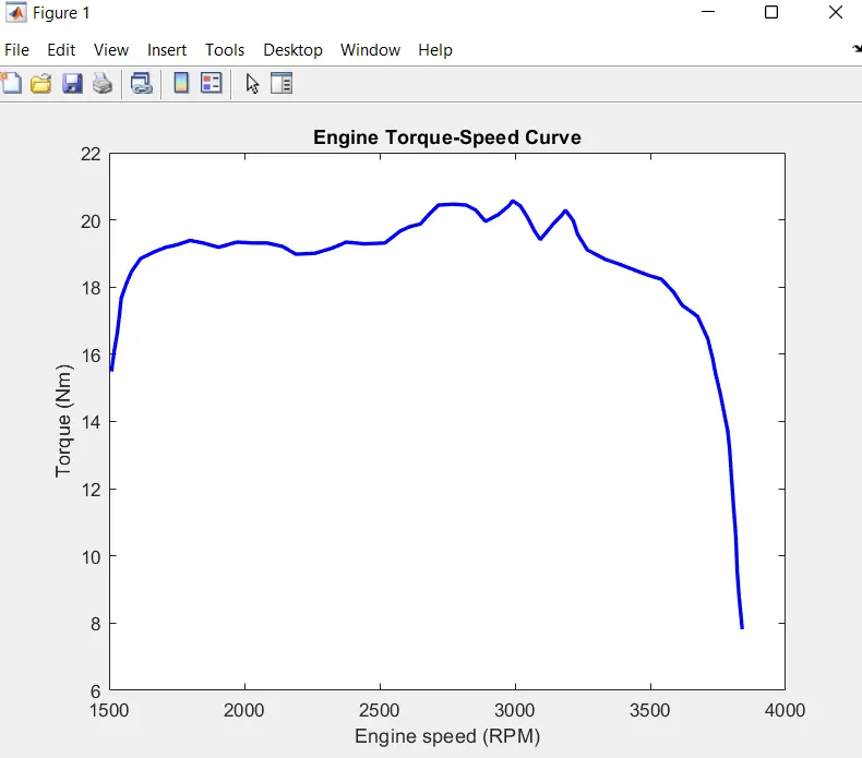
In this above graph max velocity is depend on CVT ratio.
VEHICLE SPEED PLOT:-
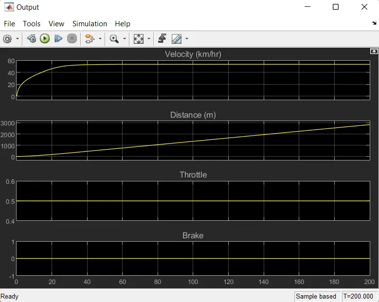
in the above Plot, the Given input of Brake Input is O and Throttle Input is 0.5 for 100 sec, Velocity will reach 53(km/hr) at
40sec and by keeping the brake input value constant, then velocity value will increase and it reaches the maximum
velocity.
CVT SHAFT SPEED PLOT:-
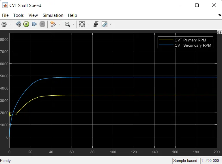
In Continuously Variable Transmission (CVT) Variator of Primary Pulley goes inward and Secondary Pulley goes Outward it
will lead to Overdrive. Primary Pulley radius increases and Secondary Pulley radius decreases So Speed of Primary
pulley is greater than Secondary Pulley.
ENGINE SPEED:-
In the above Plot, Brake Input is O and Throttle input is 0.5 for 100-sec Engine Speed will decrease at the beginning
because of increasing gear ratio which increases the torque and by increasing the Throttle input value to 0.5, then
Engine Speed value will increase and it reaches the maximum Speed
ii)Case-2: Brake input-0.2 and Throttle input-0.5
VEHICLE SPEED PLOT:
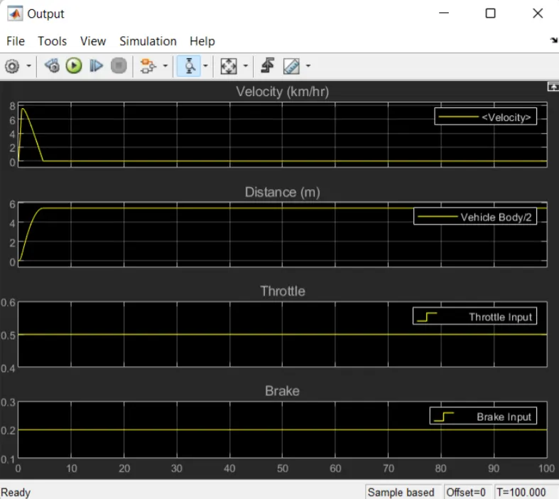
in the above Plot, the Given input of Brake Input is O.2 and Throttle Input is 0.5 for 100 sec, Velocity will reach 7.56(km/hr)
0.12sec. By keeping the throttle input value constant and brak input is 0.2 then the velocity value will decrease.
CVT SHAFT SPEED PLOT:
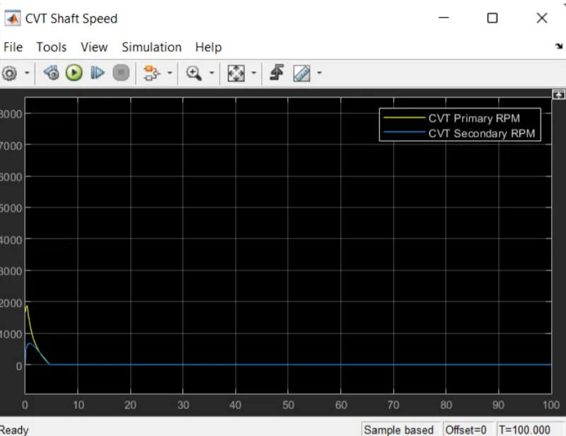
In Continuously Variable Transmission (CVT) Variator of Primary Pulley goes outward and Secondary Pulley goes inward it
will lead to slow drive. Primary Pulley radius decreases and Secondary Pulley radius increases So Speed of Primary
pulley is lower than Secondary Pulley.
ENGINE SPEED:
In the above Plot, Brake Input is O.2, and Throttle input is 0.5 for 100 sec, Engine Speed will increase at the beginning
because of decreasing gear ratio which decreases the torque, and by keeping Throttle input value to 0.5.
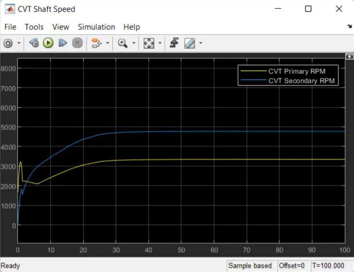
iii)case-1: Brake input-0.2 and Throttle input-0.8
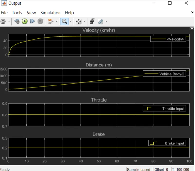
VEHICLE SPEED PLOT:
in the above Graph, the Given input of Brake Input is O.2 whereas Throttle Input is 0.8 for 100 sec, Velocity will reach 7.56(km/hr) at0.7sec. By keeping the brake input value constant and throttle input is 0.8 then the velocity value will decrease.
CVT SHAFT SPEED PLOT:-
In Continuously Variable Transmission (CVT) Variator of Primary Pulley goes inward and Secondary Pulley goes outward it
will lead to overdrive. Primary Pulley radius increases and Secondary Pulley radius decreases So Speed of Primary
pulley is higher than Secondary Pulley.
ENGINE SPEED:-
In the above Plot, Brake Input is O.2 and Throttle input is 0.8 for 100 sec, Engine Speed will increase at because of
decreasing gear ratio which increases the torque and by keeping the Throttle input value to 0.8.
Conclusion:-
Thus it is vey imp to understand the relation between the Gear speed , engine ratio nd the torque. The required speed and acceleration can be matched by varion the throttle angle and gear ratio.