Project 4
For a vehicle with a gross weight of 300 kg, the motor ratings are 1200Wh, and 65V. The range is 225km and the maximum speed is 60kmph. Calculate the capacity of the battery pack required and the number of series-parallel connections. Give a stepwise discussion on how a battery pack is built.
SOLUTION:-
We have to Do calculation part for the find the battery pack capacity for this Given Data
Given Data are,
Vehicle weight=300kg
Motor rating=1200wh,65V
Range=225km
Max speed=60kmph
We know that, calculate the Motor current
Power(P)=Voltage(V) x Current(I)
1200=65 x 1
I=1200/65
I=18.46 A
Current with drawn back Motor 18.46 Amp
Assure current loss 1-10%
After loss new motor current 18.46 x 1.05 = ~19.38 Amp
Now Calculate the Power required at max speed
At 60kmph
Power=Voltage x Current
Power=65 x 19.38
Power=1260 watt
Then We have to calculate travel Factor
Travel factor=Total Range /Total Speed
=225/60
Travel Factor=3.75
To calculate Power based on travel factor
Power requried=Power x Travel Factor
=1260 x 3.75
=4.7kw
Then we have to calculate battery pack capacity based of efficiency
we take Battery pack efficiency 85% to 95% Let suppose we consider 85%
Required Battery Pack Capacity =4.7/5.52 kw
Then we Calculate,
Battery pack efficiency based on motor efficiency
Total Battery Pack Capacity = 5.52/0.85 = 6.49 kwh
Now we have find how much connection comes in series and parallel
>>For Series connection
Motor Voltage 65 V
Cell voltage 3.7 V
No of series cells 65/3.7=18 Thus, 18 cells in series
>>For Parallel connection
Motor current 19.38/2.8=7 Thus, 7 Cell in Parallel
This all are the calculation part of Battery
Now we see how to developed Battery Pack simulations Under MATLAB
For Physical Designs, we have to consider the following steps,
The two-week process consists of the following seven stages:
Stage 1 >> Slurry Formation:
In order to generate electrode slurry, scientists combine powders containing the active minerals in electrodes like lithium with binding compounds, which act as glue, in a large bowl.
Stage 2 >> Electrode Coating:
To create a solid electrode, the slurry is spread out on a long sheet of foil (up to several hundred feet), which is then slowly rolled through intense heat (up to 300 degrees Fahrenheit).
Stage 3 >> Electrode stamping:
In order to press the baked electrode roll beneath a razor-sharp rectangular die, it is first sliced into smaller pieces. In a single swift motion, the die presses down on the electrode sheet and separates one electrode battery component.
Stage 4>>Electrode stacking:
Suction is used by a robotic system to take up and release sheets of electrode material, and an insulating layer is sandwiched between the electrodes. A stack of electrodes about the size of a credit card emerges from the machine at the flick of a mechanical arm.
Stage 5>>Pouch making:
These rectangular shapes are made by pressing a specific barrier material that is impermeable to water. A pouch cell is made by inserting an electrode stack inside the resulting shape.
Stage 6>>Electrolyte injection:
Liquid electrolyte is injected into an open battery pouch.
Stage 7>>Battery sealing:
An electrolyte-filled battery pouch is heat-sealed before being placed in a vacuum chamber.
The pouch cells are put through their paces by being continuously charged and discharged in temperature-controlled rooms set to conditions that simulate temperatures between 20 and -140 degrees Fahrenheit.
If the performance of a test pouch cell is satisfactory, the novel combination of these materials may one day allow us to live longer, more productive lives. After a potential battery formulation has been discovered, national laboratories collaborate with private enterprises to licence the technology, which is then developed into a product that can be brought to market so that we may all buy and benefit from it.
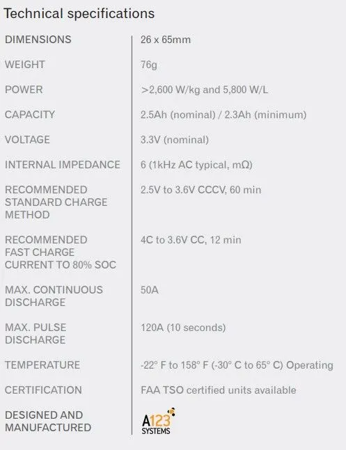
The Data Sheet Required for the same is Attached below:
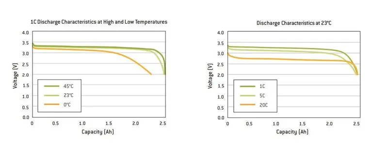
Discharge Characteristics at Low Temp:
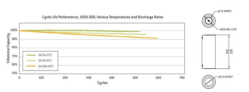
Cycle Life Performance:
__________________________________________________________________________________________