Project 3
Solution:
Info Provided, Vin = 48V and Vout = 12V; Output Current = 5A
Inductor current ripple is less than 30% of the average inductor current
output voltage ripple of the capacitor is less than 5%.
Schematic diagram of the buck converter
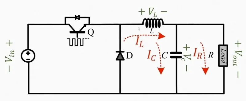
Converter Circuit in ON & OFF mode.
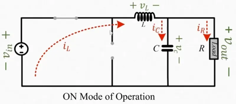
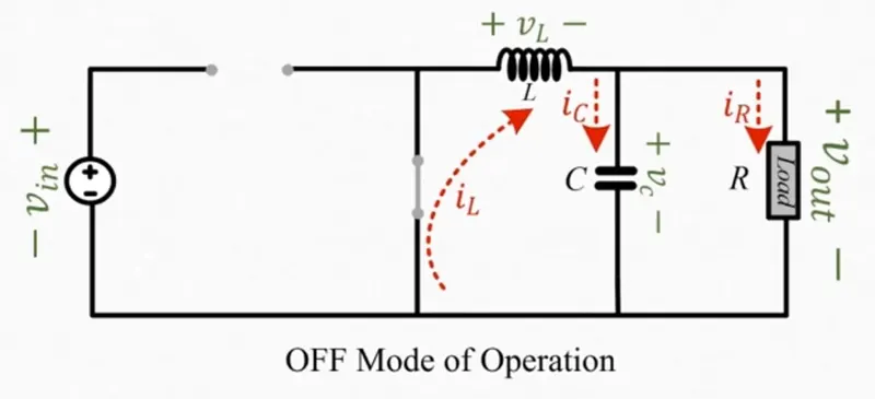
Calculation Involved:
VL = [(Von x D x T) + (Voff x (1-D)T)] / T
Where,
- Von = Vin - Vout
- Voff = - Vout
Therefore, Duty Cycle (D) = V out / V in = 12/48 =0.25
Vout = Iout x R Thus, R = V out / I out = 2.4 Ohms
For Designing the Inductor for 30% pf ripple in Inductor
IL = [ 30 / 100 x 5] = 0.3 x 5 = 1.5
L = [ Vout / Fs IL] x (1-D)
L = 0.12 Units
For calculating capacitor C,
C out = (1-D) / [ 8 x L x fs^2 ( Vo/Vo)]
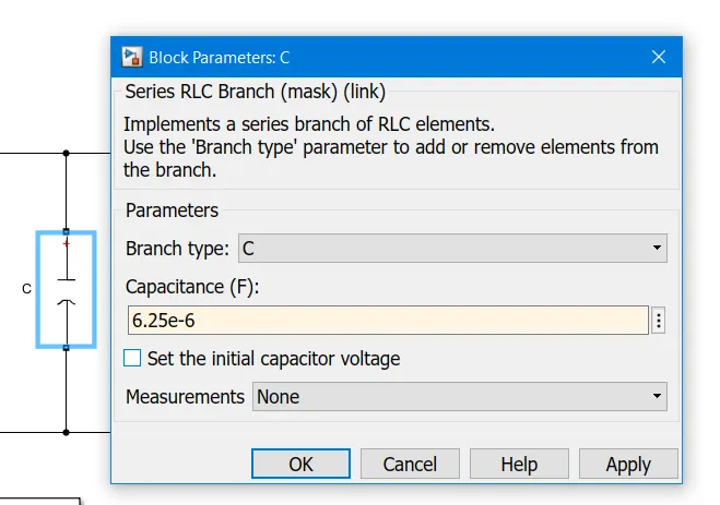
Inserting the Values we get C out ~ 0.00625 F (Farads) or 6.25μF.
Now we have,
R = 2.4ohm; L = 0.12mH; C = 6.25uf; D = 25%; Assumption f= 50kHz
SIMULATION:
Step signal block, PWM Generator DC-DC, MOSFET, Diode, Voltage source, L, C, R, Scope, etc.
Now Configure each element according to our requirements.
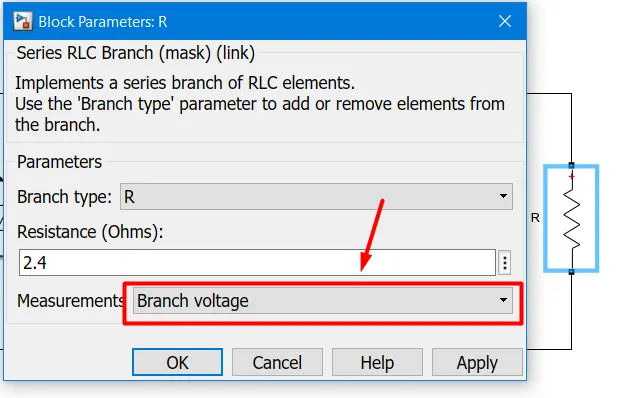
Set R = 2.4ohm
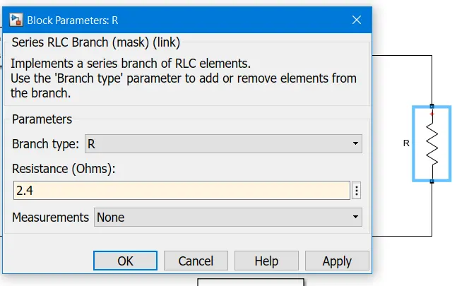
Enable Measurement to measure the Output Voltage.
Set Capacitance Value as calculated 6.25uf.
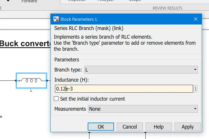
Set Inductance Value as Calculated 0.12mH with Measurement Enable for branch current.
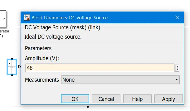
Set Input Voltage 48V
Set Frequency to 50kHz as supply frequency in India is 50kHz.
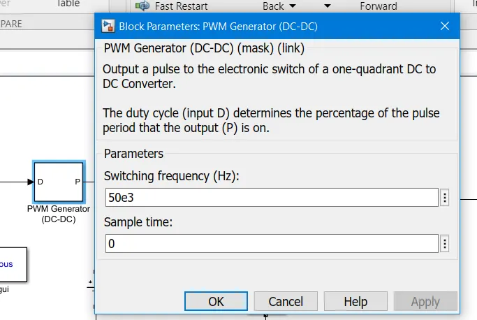
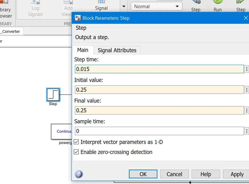
set Step block as the Duty cycle of 0.25.
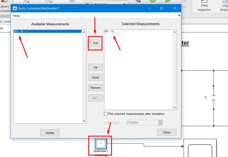
configure the Multimeter block as we already activated the resistor branch voltage measurement and inductor branch current.
double-click on the multimeter block and select the signal accordingly.
Connect According to the given Screenshots:
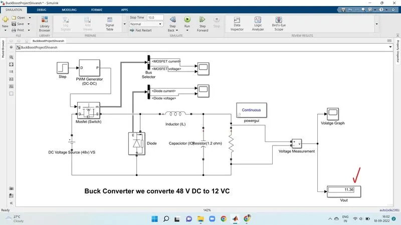
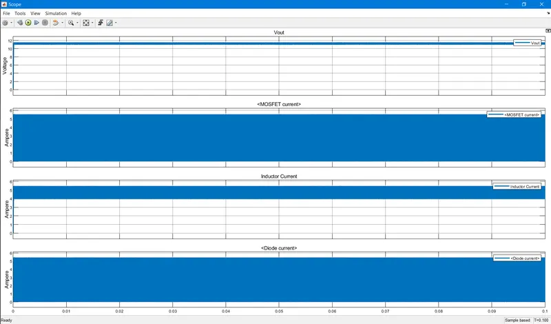
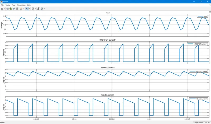
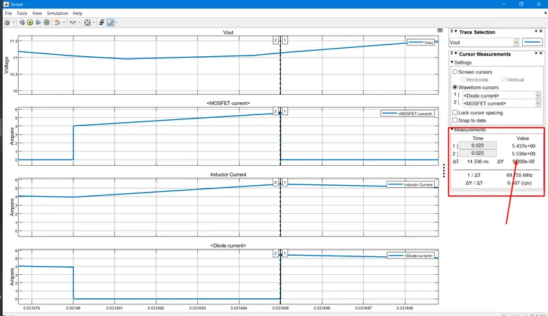
MOSFET Current and Diode Current:
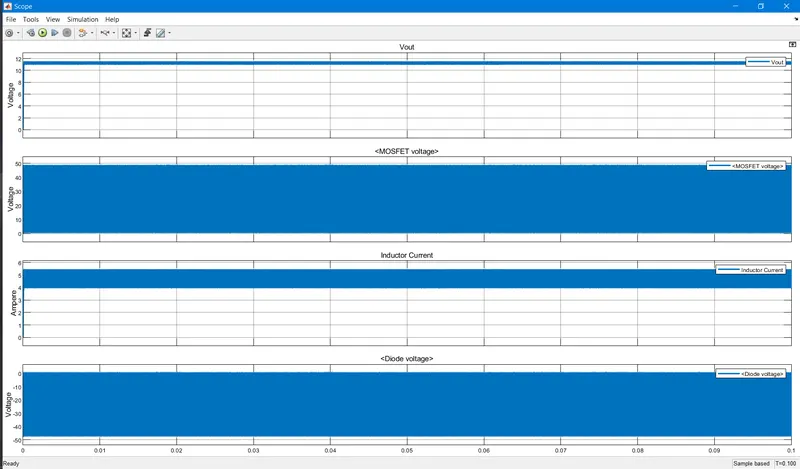
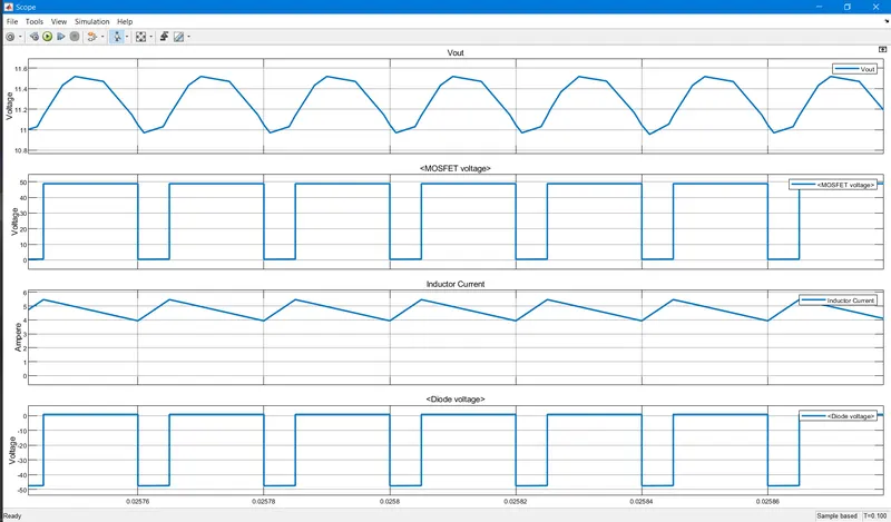
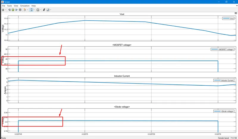
MOSFET Voltage and Diode Voltage
Notations:
What are the peak voltage and current values of your switches (Mosfet and Diode)?
Peak Voltage of Mosfet = ~49V
Peak Voltage of Diode = ~0.8V
Peak Current of Mosfet = 5.5A
Peak Current of Diode = 5.4A
[Please find Attached .slx File]