Project 1
Question: Design and Develop a PWM controlled fan load with DC motor.
Explaination:
The Fan's rotational velocity may be altered by adjusting the voltage applied to the motor. A DC motor with an attached fan.
The "Stator" refers to the motor's motionless outer shell, while the "Rotor" refers to the moving, internally-mounted component that generates rotation. The rotor is more properly known as the "Armature" in DC machines. Small, light-duty DC motors often use a "permanent-magnet direct-current" (PMDC) motor's stator made out of a pair of fixed permanent magnets that create a consistent and stationary magnetic flux inside the motor. The armature of the motor is made up of separate electrical coils that are coupled together in a circular pattern around its metallic body, resulting in a North-Pole, South-Pole, North-Pole, etc., kind of field system configuration.
These rotor coils generate the required electromagnetic field thanks to the current passing through them. When the armature's windings generate a circular magnetic field, north and south poles are created around the armature; these poles are either repelled or attracted by the stator's permanent magnets, causing the armature to rotate around the motor's central axis.
2-Pole Permanent Magnet Motor
With each revolution of the armature, a fresh magnetic field is created by the carbon brushes surrounding the commutator, energising the next set of armature windings and so on.
Controlling the interplay between the magnetic fields created by the stator's stationary permanent magnets and the armature's moving electromagnets allows us to regulate the DC motor's rotational speed.
The magnetic field generated by the stator's permanent magnets is unchangeable, but the electromagnetic field generated by the armature can be adjusted by varying the amount of current passing through its windings, thereby altering the strength of the interaction between the two components and causing the motor to either speed up or slow down.
Then the rotational speed of a DC motor (N) is proportional to the back emf (Vb) of the motor divided by the magnetic flux (which for a permanent magnet is a constant) times an electromechanical constant depending upon the nature of the armatures windings (Ke) giving us the equation of: N ∝ V/KeΦ.
PWM Method
Pulse width modulation speed control, as its name indicates, works by operating the motor with a sequence of "ON-OFF" pulses and altering the duty cycle, or the ratio of "ON" to "OFF," while maintaining a constant frequency.
By adjusting the duration of these pulses and, in turn, the average DC voltage at the motor's terminals, the power delivered to the motor may be fine-tuned. The on-time of these pulses determines how quickly the motor spins; the longer the on-time, the faster the motor spins, and the shorter the on-time, the slower the motor spins.
In other words, as indicated in the diagram below, the greater the pulse width, the greater the average voltage delivered to the motor terminals, the greater the magnetic flux within the armature windings, and the quicker the motor would revolve.
Pulse Width Modulated Waveform
Since the switching transistor is either "ON" or "OFF," the power loss is minimal when using pulse width modulation to regulate a tiny motor. Lower power dissipation and more linear control provide more consistent speeds thanks to improvements made to the switching transistor.
The amplitude of the voltage supplied to the motor is fixed, guaranteeing that it operates at maximum power at all times. This allows the motor to be turned considerably more slowly without stalling. By connecting a H bridge circuit to a DC motor, this demonstrates the design work for a PWM-based fan speed control system. Instead of using a physical fan model in Simulink, we have analysed the output findings using a fan-type load equation. The PWM approach is used to adjust the fan speed in response to changes in the input voltage.
By changing or modulating the timing of these pulses the speed of the motor can be controlled. A stepwise change in the speed variation is given and the full load speed is observed. In this model, all input ports of the H-Bridge block except the PWM port are connected to ground. As a result, the H-Bridge block behaves as follows:
- When the motor is on, the H-Bridge block connects the motor terminals to the power supply.
- When the motor is off, the H-Bridge block acts as a freewheeling diode to maintain the motor current.
Model Diagram in Simulink
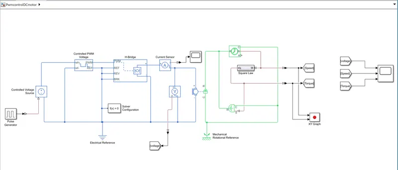
Model Explanation:
Torque exerted by fan represented by TL
Load torque i.e. TL proportional to square of speed i.e. wm^2
TL = C . wm^2
By varying the electrical parameter of motor i.e. voltage and current we are controlling load torque or load speed.
For fan load we don’t have any block to represent a fan so we are representing by a subsystem
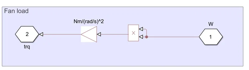
to the left side there is w and it is multiplying by product block then it is become w^2
Then gain block is used that is the constant of proportionality 8.8e-8 Unit of this gain block is N*m/(rad^2/s^2
Output of this subsystem is fed to the Aerodynamic block. Actual name of this block is
Ideal torque source block. This ideal torque source block is going to apply torque on the shaft of DC motor.
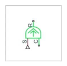
For getting the speed we used Motion sensor.Value of the motion sensor w is given to the subsystem w and the value of the torque is given to the aerodynamic block and therefore completing the loop.
Controlled voltage source is connected to the controlled PWM voltage and H-bridge is connected through PWM voltage.
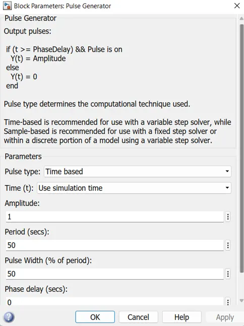
Pulse generator block used as input to the controlled voltage source.
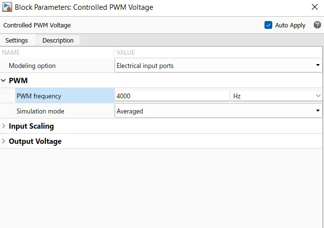
The Controlled PWM Voltage block represents a pulse-width modulated (PWM) voltage source. You can model electrical or physical signal input ports by setting the Modeling option parameter to either:
- Electrical input ports— The block calculates the duty cycle based on the reference voltage across its ref+ and ref- This option is the default.
- PS input— Specify the duty cycle value directly by using an input physical signal port.
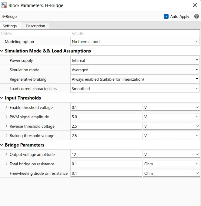
- The H-Bridge block represents an H-bridge motor driver. The block has the following two Simulation mode options-
PWM — The H-Bridge block output is a controlled voltage that depends on the input signal at the PWM port. If the input signal has a value greater than the Enable threshold voltage parameter value, the H-Bridge block output is on and has a value equal to the value of the Output voltage amplitude parameter. If it has a value less than the Enable threshold voltage parameter value, the block maintains the load circuit using one of the following three Freewheeling mode options.
H-bridge used to change the direction of motor. Basically, it is used to turn the motor is in clockwise direction or anti-clockwise direction.
we can use a H-Bridge motor driver for the DC motor which helps in reversing the polarity of the motor to run it in the reverse direction. So whenever the brakes are applied the command is given to the H-bridge and it reverses the polarity of the motor thereby making it works as the generator and the energy produced is given to the batteries.
So by the help of H-bridge we can implement the Regenerative brakinng in system.
PWM signals are provided to the H-bridge, and output of H-bridge is given to the Dc motor through the current sensor and voltage sensor.
The DC motor is driving the fan load , we are taking the speed output from the Dc motor through the motion sensor. And pass it to the subsystem.
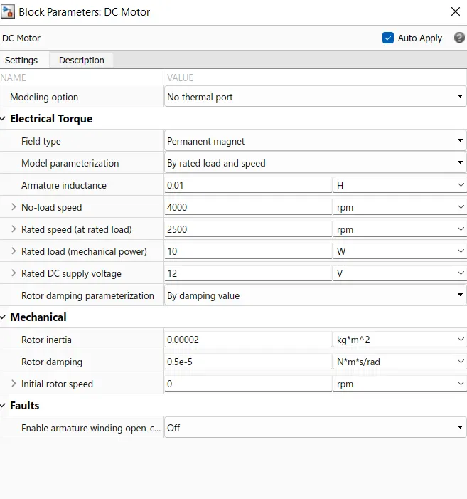
Parameter needs to update.
In PWM voltage block set PWM frequency as 4000 Hz
H-Bridge parameters
Dc motor configuration
Output Result of XY Graph
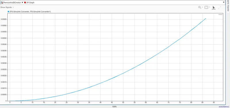
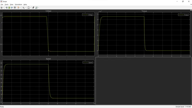
Output result of scope