Project 3
Project - 03 Design of 2Lane Village road
Aim is to design a 2 Lane village road and prepare drawings.
Data provided is Survey data in .csv file
Design Parameters:
Type of Road : Village road
Road : 2 Lane with Shoulders
Road width : 3.75 Lane either side with 1.5m Paved shoulders
Pavement: Asphalt pavement
Design speed : 50 Kmph
Minimum vertical curve length : 30m
Minimum gradient : 0.5%
Max. gradient : 5%
Super elevation Max : 5%
The entire design process is divided into small tasks and the procedure followed in designing the project is explained in words with pictoral depiction of screenshots during the design of road.The procedure is explained below.
Task-1 Creating a Terrain model :
As the project is India Metric system is used and hence metric workset is choosen for the current project.
Create a new dgn file with training metric.
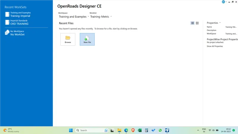
Name the file as Existing terrain and Select 3D metric seed file.
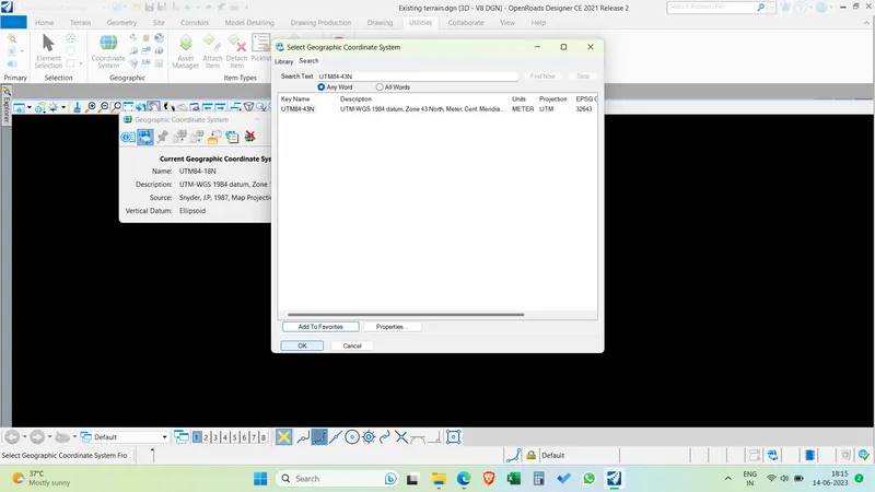
Enter the GCS as UTM84-43N.
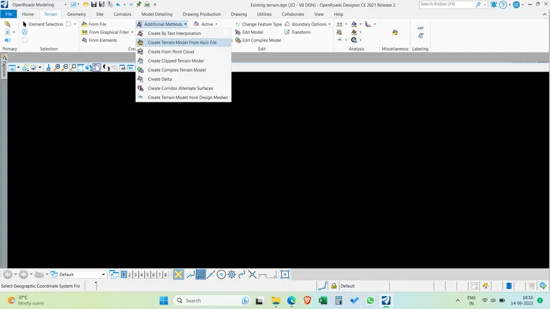
Create terrain model by using from the ASCII file
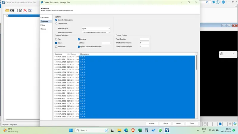
USe the text import settings and give ENZ format and create terrain model.
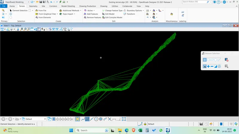
Terrain model is created with triangulation.
Task 02 Horizontal and Vertical Alignment :
Create a new dgn file named Alignment.
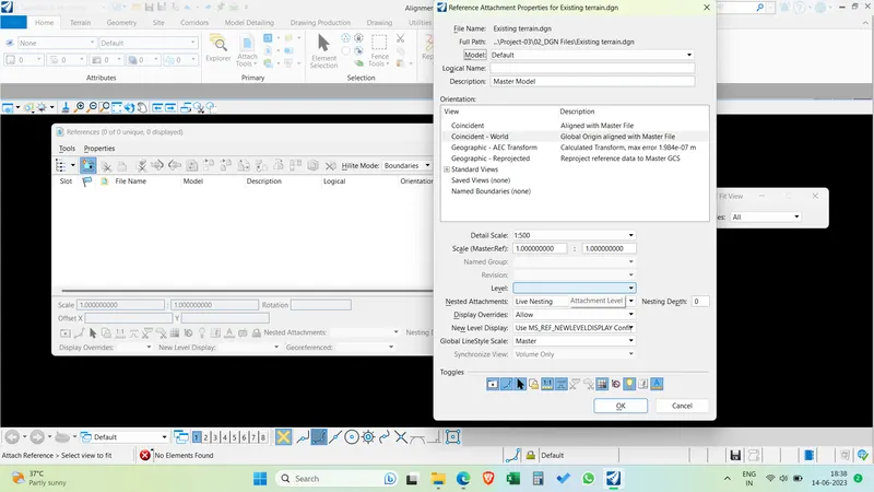
Attach the E terrain dgn as reference.
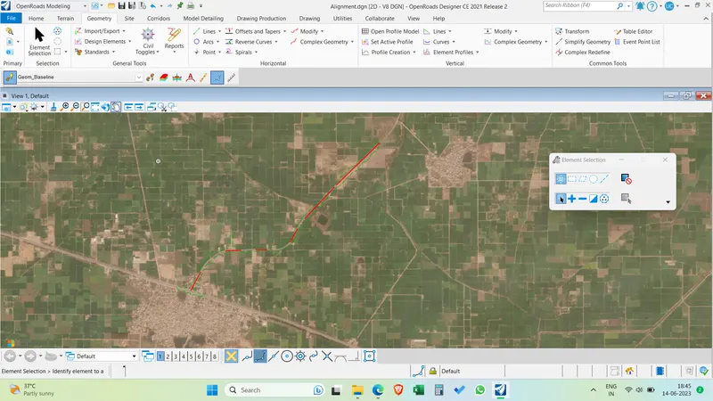
Create horizontal alignment by following the existing road and place the tangents in the straight portion wherever possible.
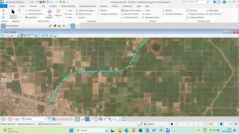
Insert horizontal curves between tangents. By using the IRC code give the transition lengths for spirals wherver it is necessary.
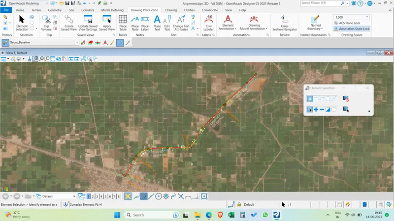
Do a complex geometry and give stationing from 100+000 as start chainage.
Annotate the geometry.
Open the profile model for village road and set the terrain as active.
Start create a offset profile from ground at 200mm above ground as to provide a embankment for village road.
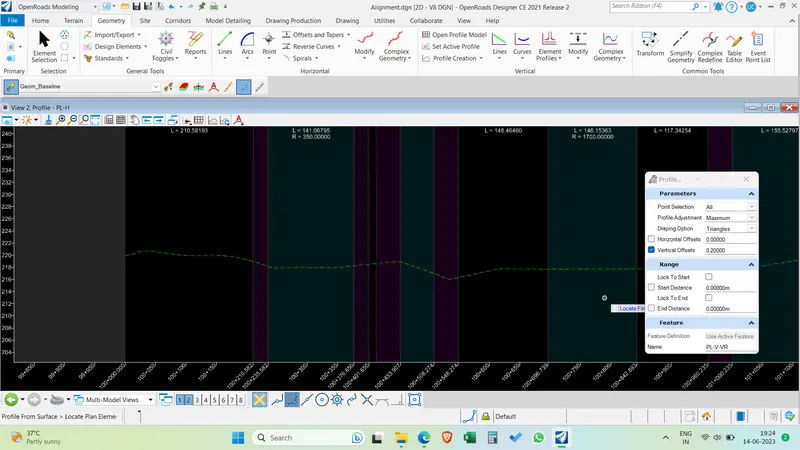
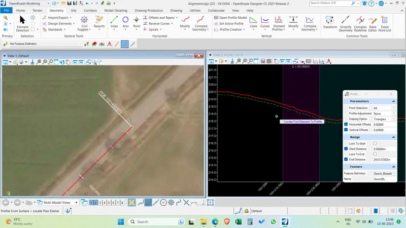
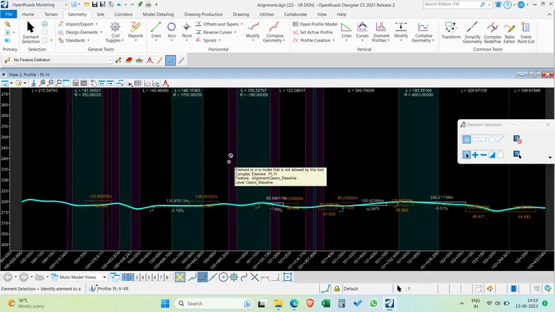
Create alignment by using the parameters of Minimum gradient of 0.5% and a Maximum gradient of 5% and minumum curve length of 30m for design speed of 50Kmph and maintaining the 200mm height above the ground.
After Vertical profile is created set the profile as active profile.
Task 03 Road Layout:
Create a new dgn 2d file named Road layout
Attach E terrain and alignment dgn files.
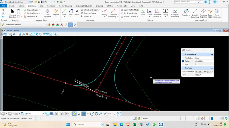
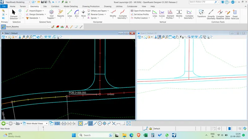
Offset the alignment base line with 3.75m either side with Road Edge of pavement as feature definition.
Create a partial offset of 5.5m for a length of 100m from start of project for the left turn lane at junction.
Taper the extra lane for 40m length.
Create fillets at the junction with village road with 25m radius at main juntion and 10m radius for side road junction.
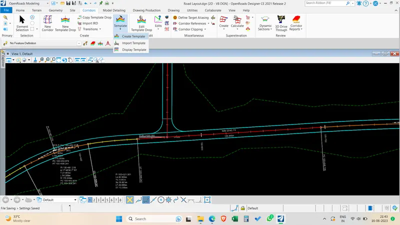
Template creation:
Go to corridors and click the create new template.
Copy the Rural Undivided asphalt pavement template and rename it SL village road.
Delete the end conditions and insert end consitions with 2:1 Fill and 2:1 cut condition and save template.
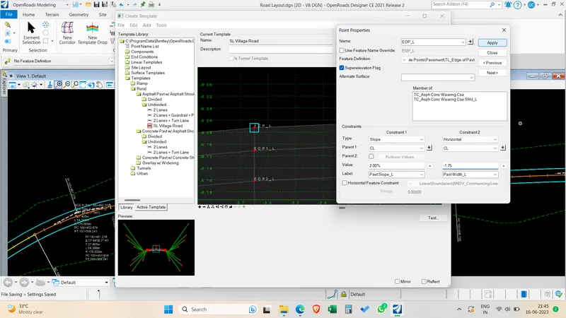

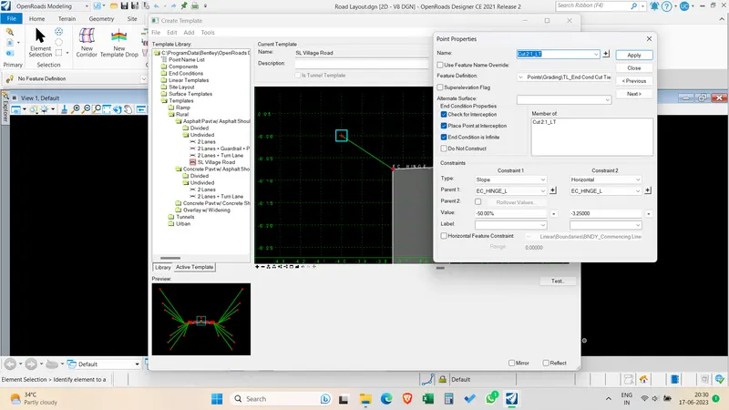
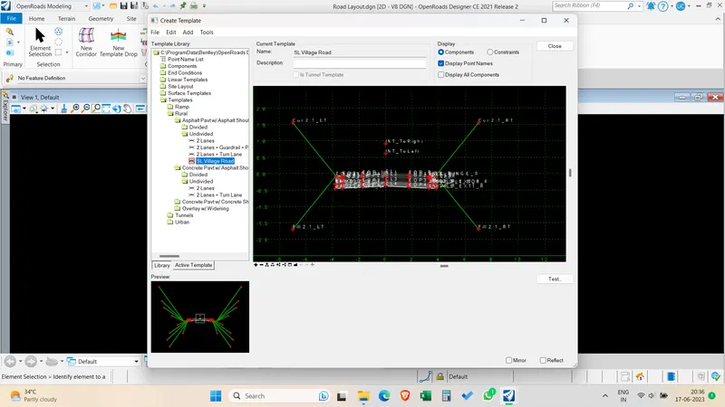
Task 04 Super Elevation
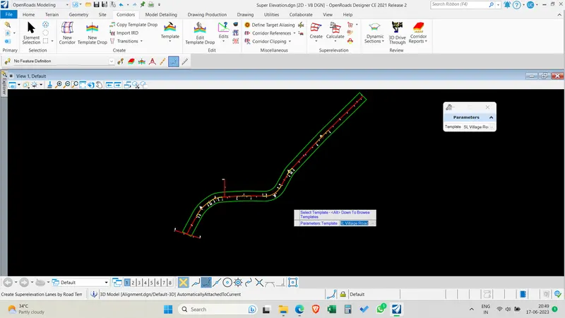
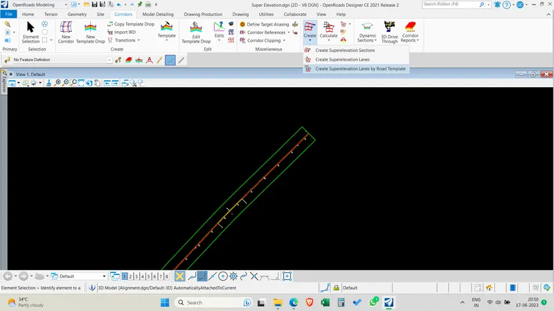
Go to corridors and use the create superelevation corridor by selecting the entire alignment and the tempplate we have created earlier.
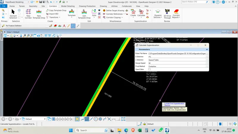
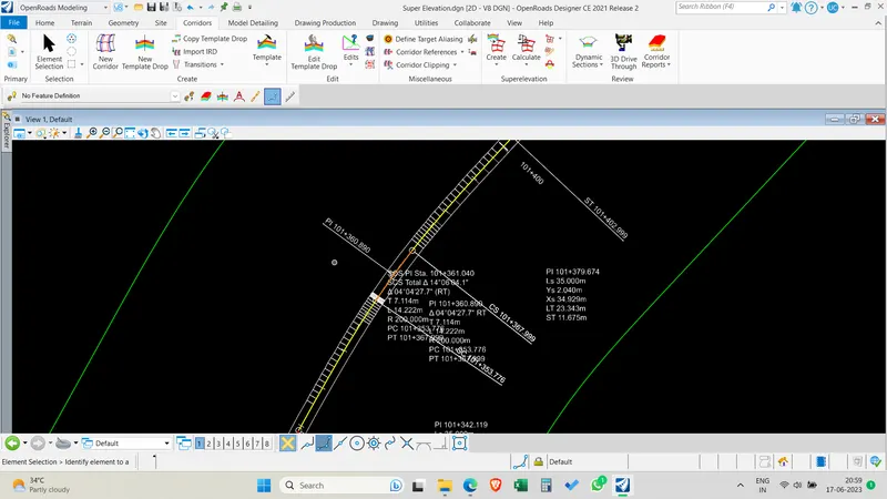
Calculate the super elevation by using the AASHTO 2018 metric file with 5% e max and 50 KMph speed table and pivot method of centerline.super elevation is created.
Task 05 Corridor Modelling:
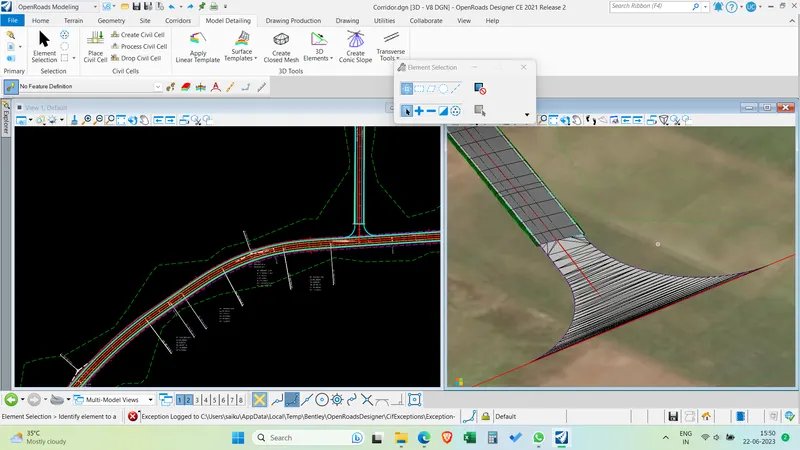
Create corridor dgn file and attach all dgn files necessary and create a corridor by selecting the SL village road template we have created earlier.
Open plan/3D view to see the corridor model created in 3D view.
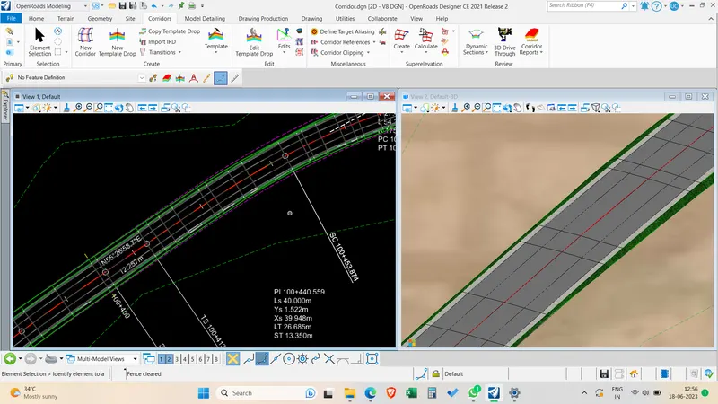
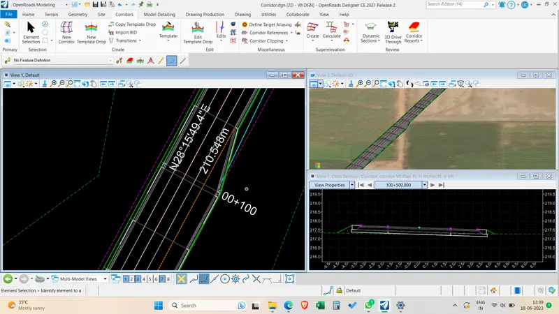
Open 3 Views Plan/3D/XS views to see the cross section created at intervals of 10m.
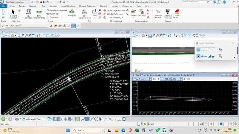
Create a point controls at the turn lane taper portion to create a template taper from 5.5 to 3.75 on right side.
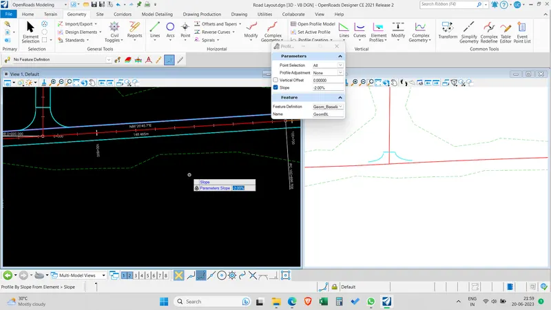
Open road layout dgn file and create profiles for junctions and cross lines created for using the taper area as surface templates.
Use the Element profiles, Profile by slope from element and create profiles at Road Egde lines and also at junctions.
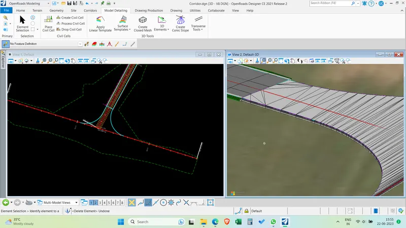
Do a quick profile transition for the all the three side of junction taper areas ath both the junctions.
Create terrain by elements and select the edge lines at junctions to create the terrain surface.
Go to model detailing and Click Apply surface template to created terrain model.
Surface is created with selected asphalt road template.
Task 06 Component Quantity Calculation:
Use the civil analysis > Element component quantities
Select the alignment and corridor.
Component quantities are generated.
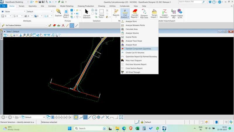
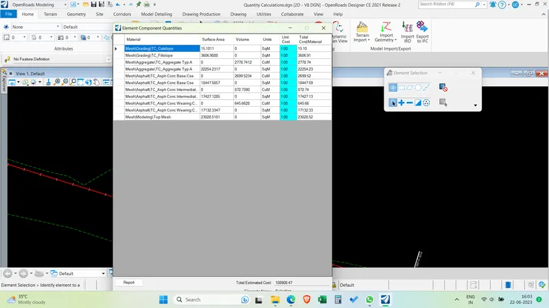
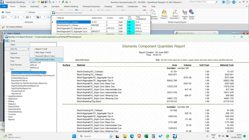
Save the report as excel sheet.
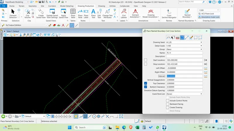
Drawing production > Place named boundary > civil cross sections at 25m intervals.
Civil Analysis > Select the alignment components and create the end areas at 25m intervals.End Area with cut fill volume report is generated.
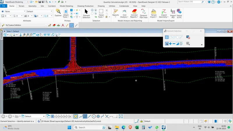
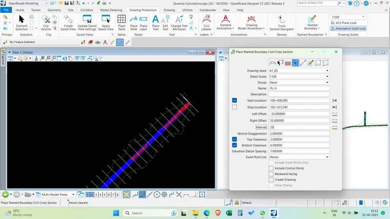
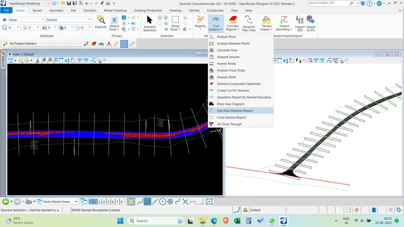
Task 07 Report generation:
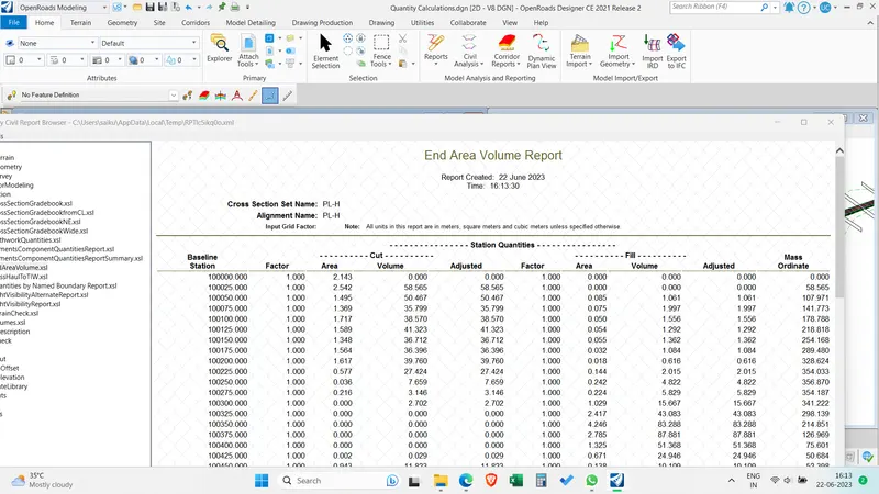
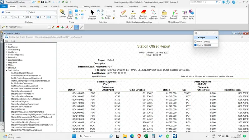
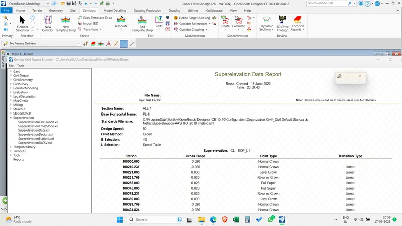
Task 08 Plan and Profile drawings
Go to drawing production > Place named boundaries > create plan profile drawings.
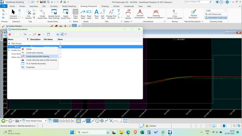
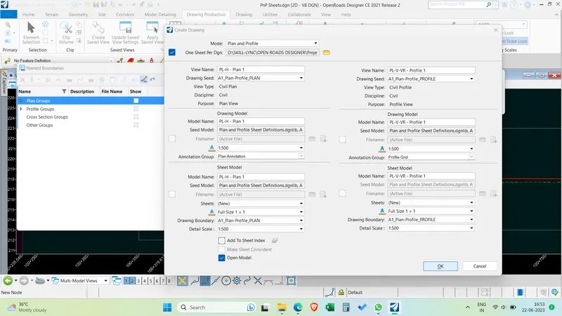
Drawing seed as A1 Plan profile plan and A1 Plan profile profile for profile group.select plan group for profile to attach in same sheet.
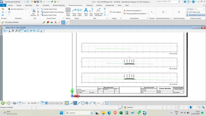
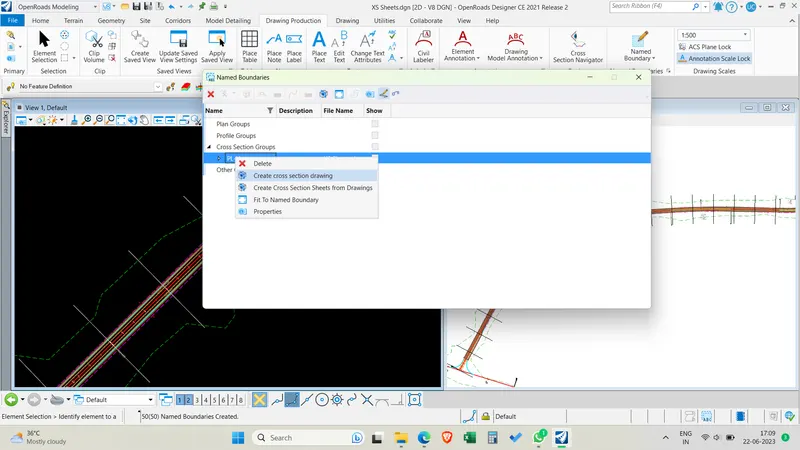
Create cross section group at 50m intervals with A1:XS sheets.
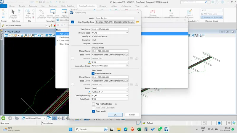
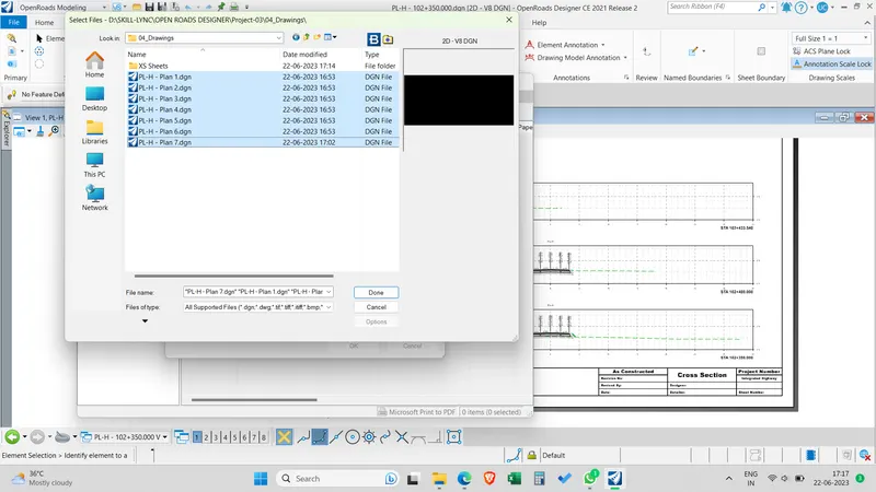
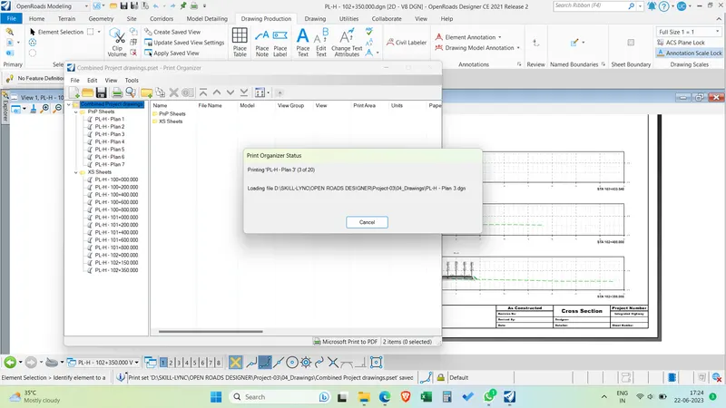
Open print > Print organiser > Create a new group and add folders for plan and profile and add all the PnP sheets created.
Create a new group named XS sheets and add all the XS sheets created.
Save the group as Combined group project drawings and print all the drawing as PDF.