Project 2 - Lane National Highway Roadway Design in Civil 3D
Questions:
- Creation of surface.
- Alignment & profile design.
- Creation of assembly & subassembly.
- corridor development.
- Section line & detail cross section.
Attachments:
- Civil 3d Project file.
Detail Procedure:
Creation of surface.
- Open Civil 3D Metric.
- Click File > then select New > Select the template provided in data downloaded > Open the Skill lync template > Template will be selected with all the settings.
- To Save the project enter ctrl + s > then select the folder where u want to save the project > Name the project.
- There is a tool space at the left to the viewport with 4 sub tabs or sections.
- Prospector where you can create and modify civil 3d entities or elements
- Settings tab where you can review and modify all the settings of the file.
- Survey tab is used to review and check all the survey data and modify the survey data.
- Tool box tab is used to Export the file data to land xml file and generate all the reports of survey,alignment,profile, quantities, cross sections etc.
- In the Prospector tab > all the elements of civil 3d road projects are displayed. Select surface and right click> then select create surface > Name the surface.
- Then Add contour data > Definition > Contours > Right click > Add > add description > Name as you wish .
- Select the Contour lines > Enter > Your surface is created using the contour survey data.
- You can change the surface display type by right click on created surface in the Prospector > Surface tab > All select any type of displayin the surface.
Creation of surface by using Land xml file:
- After saving the template as a project file click on File > Select import from Land xml file > Select the land xml file from the folder.
- In the Prospector tab > Select surface and right click> then select create surface > Name the surface.
- Then Add survey data > Definition > Contours > Right click > Add > add description > Name as you wish .
- Select the land xml data > Enter > Your surface is created using the land xml survey data.
- You can change the surface display type by right click on created surface in the Prospector > Surface tab > All select any type of displayin the surface.
Que-02: Alignment & profile design.
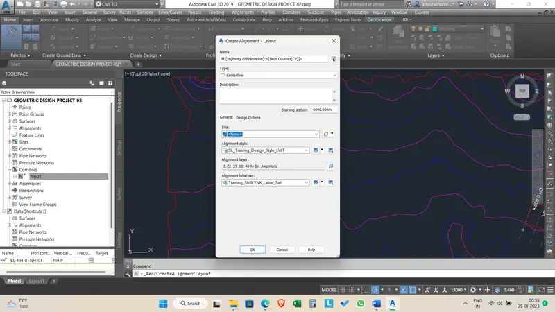
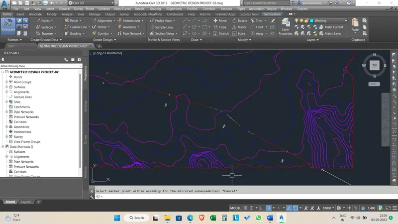
- To create alignment, Home > Click on Alignment > select create alignment - Layout > Assign a name > Skill set select as SL Training-LWT > Label set as Skill lync label set > Click ok.
- Now the alignment is created in Prospector tab and alignment layout tool is displayed on screen.
- Using the alignment tool , click on line > select draw fixed line(Two points).
- Selct the starting point of the alignment and start to draw the line in the direction of the proposed alignment.
- Connect the tangents with a spiral curve using the curve creation button in layout tool > Select Free spiral (Between two entities)
- Select the first entity > Select select entity > Enter the length of the curve required > then enter spiral transition length in and out as per IRC and the curve is created between two tangent lines.
- Add tangent straight lines and curve through the alignment and join them until the end station.
- Alignment is created.
Profile creation :
- To create the profile Go to Home > Click on Profile > Select create profile from surface from dropdown list > Select the surface u created > Then click add > select draw in profile view >
- Create profile view tab > Select the alignment > Give a prifile name > Select SL-10 x exaggeration >Station range > Profile view height> Give the maximum and minimum value to view in profile> Click next > Select band set > Training 2 lane Band set > Next > Create profile view > Select the base view > Profile created as for existing surface.
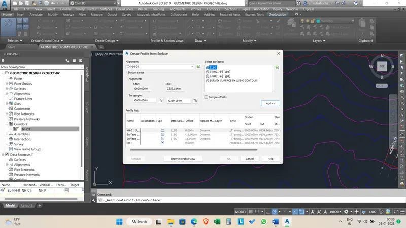
- Click on profile > Select create profile from surface>Enter -15,15 in sample offsets >Click on Add> Select the profile and change their styles to differentiate with colours > Click ok. Profile is created for existing surface at 15m left and 15m right to alignment.
- Click on Profile > Create profile by layout > Click on profile drawing > Name the profile > Select the profile style as proposed ground > Click ok.
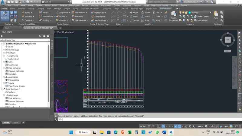
- Profile layout tools > Select draw tangents > Draw the tangets upto the end station> Click on Insert PI > Select the point on profile where u want to insert the point > Select free vertical curve (Parabola) > Select the first entity and second entity > Provide a curve length > Enter. Profile is created.
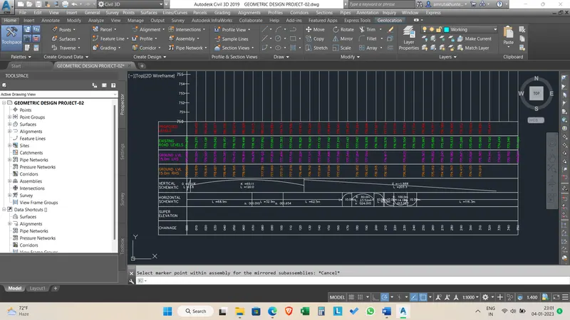
- Click the profile line > Right click on the profile > Profile view properties > Bands> Select the Profiles and assign Profile 1 and Profile 2. For Proposed level profile Select the Profile u created. For the Existing and 15m left , 15m right select the profiles u have created. For Vertical geometry select Proposed line. For chainage select Proposed line. Then click on OK. Profile view is created.
Que-03:Creation of Assembly & Sub assembly.
- To create assembly Go to corridors on Home ribbon > Click on corridors > Create assembly > Name the assembly as TCS-1 or any as you wish > Click ok.
- A interstion point appears on the screen > Click on point > Tool palette appears for assembly > select common assembly lanes > Lane from taper median > Assembly entity is displayed on screen > Right click on assembly > Select Sub assembly properties.
- On subassembly properties > Select the parameters > Give lane width as 3.5m as per basic data > Slope as 2:1 > Camber as -2% for rigid pavement > Earthen shoulder>slope -3% > Provide pavement thickness for all the layers as per pavement crust> Apply >Ok. Assembly is created.
- Copy the assembly and paste right next to carraigeway > Right click on entity > Go to sub assembly properties> Give paved shoulder width as 2.5m > All other parameters are same as carraigeway > Click apply. Paved shoulder is created.
- To create earthen shoulder> Go to shoulder on assembly tool palette >Shoulder extend all > Right click on entity > sub assembly properties > provided width of earthen shoulder as 1.5m > shoulder as Daylight 2:1 > Sub slope as -3%> Enter all the pavement thickness > Then click OK. Assembly is completed.
- Select Assembly> Basic assembly . Select and Mirror the pavement > TCS Assembly is created.
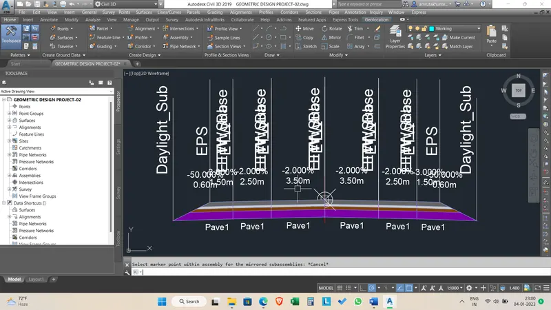
Que-04:Corridor Development.
- Click on corridors > Create corridors > Give a name to the corridor > Select the assembly to assign to corridor we have created earlier > Select target surface as Proposed surface > OK >Ok > Rebuild the corridor
- Go to corridors > Surfaces > Create > Select the create button and Specify code > Click on + sign to add the code specified> Datum > Rebuild the corridor > Corridor is created.
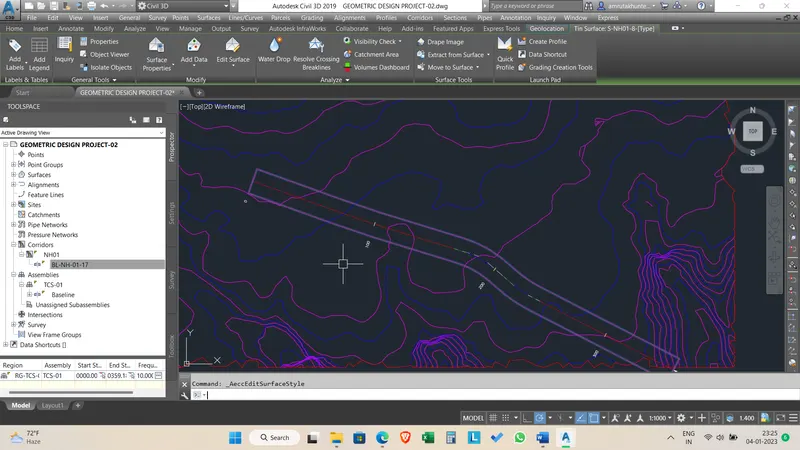
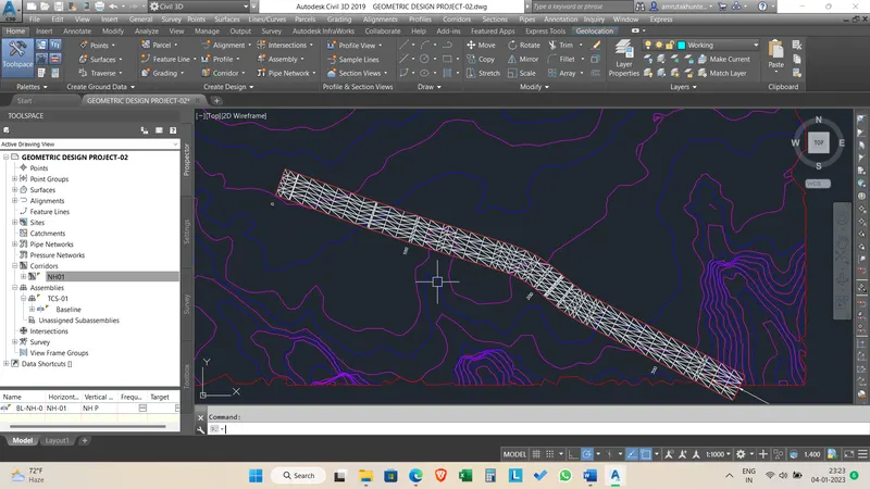
Que-05:Section lines and Detailed cross section.
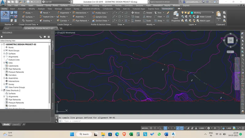
- Go to sections > Sample sample lines >Select Alignment > Enter> Ok.
- Sample lines window > Give a Name > SL-01 > Click ok.
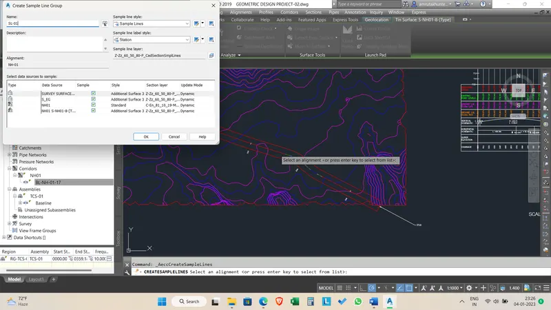
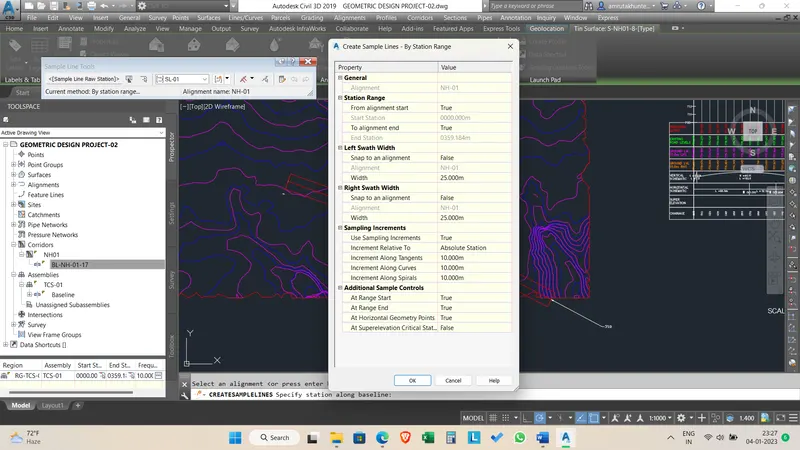
- Sample line tool appears > By range of station > Give start and End station as you require > Left swath as 25 and right swath as 25
- Increment along Tangent - 10 , Curve - 10 , Spiral - 10. Then Click ok > Right click on start of alignment. Sample lines are created between stations we have entered.
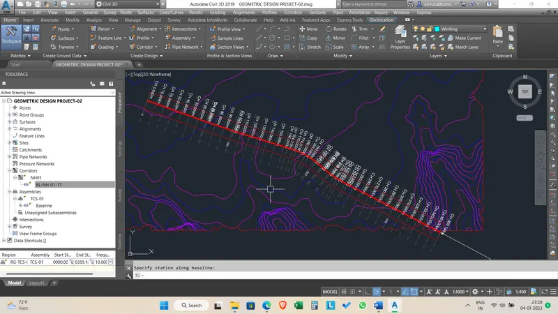
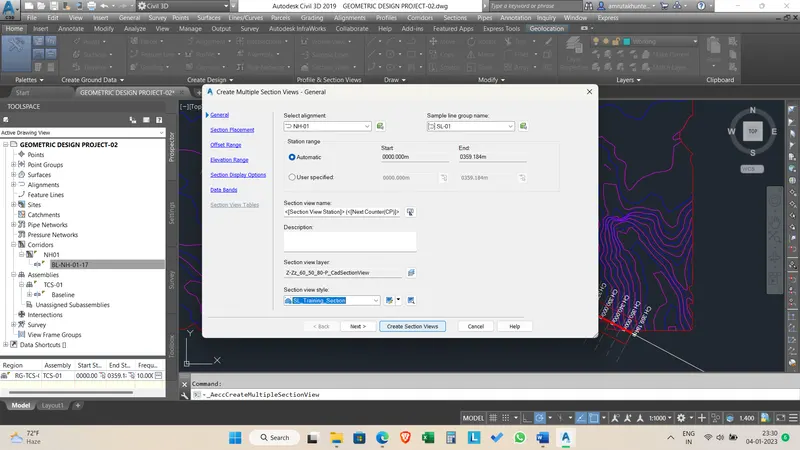
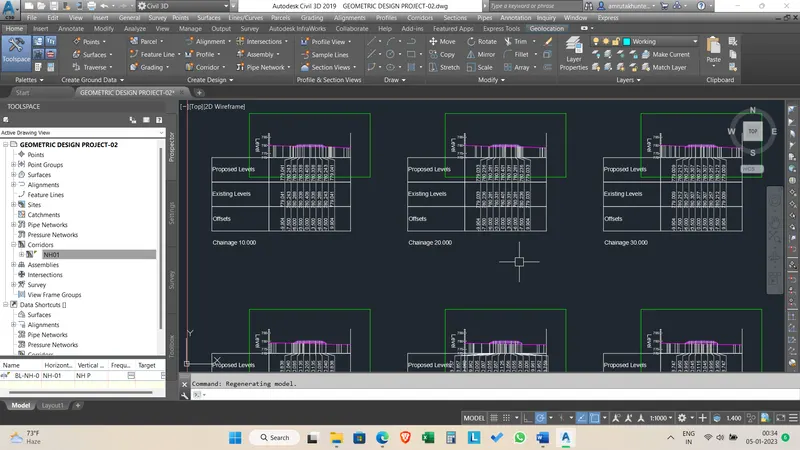
- Sections > Create multiple sections > Select Alignment > Section view > Create section views.