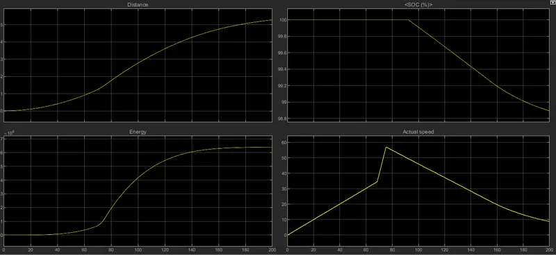
Project 2
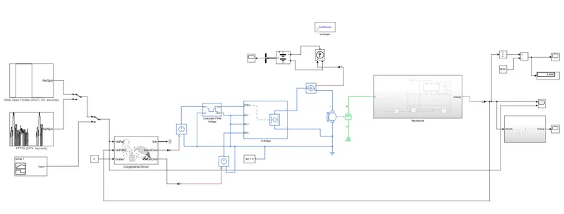
Fig below shows the developed simulink model
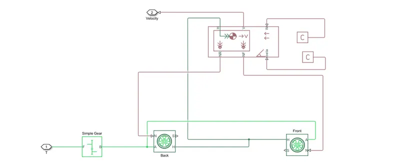
The vehicle subsystem is modelled for ebike as shown below
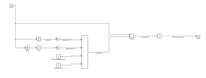
System for analysing energy during each cycle is shown below
- Here, a motor with an oprating voltage of 300V is choosen as driving source.
- The motor is fed by a pwm controlled H-bridge converter.
- The command signal for controlling duty ratio of PWM is given through longitudinal driver block set.
- Different driving cycles are given as input for longitudinal driver block.
- Energy is calculated for each driving cycle
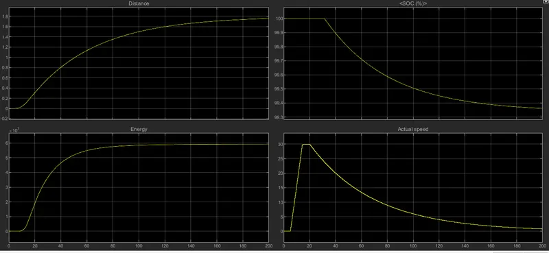
The output for different driving cycles is as shown below.
Wide open throttle
FTP75
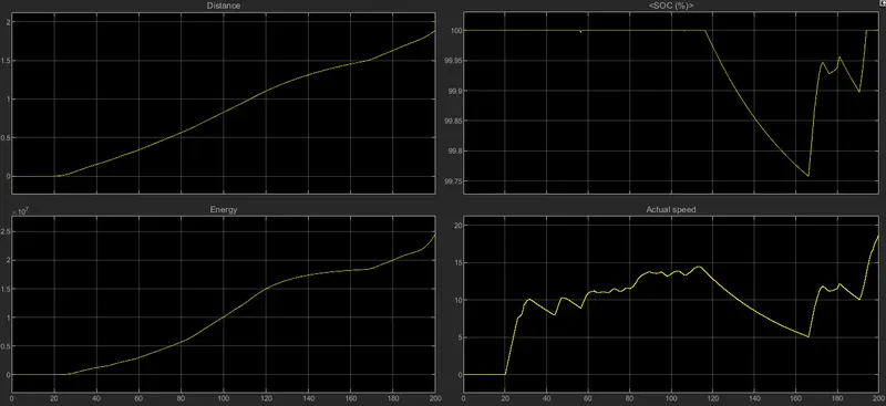
Custom signal